Seismic Analysis of a Multi Storey Building
with and Without Floating Columns
Govardhanam Srikanth1, Dr. Shaik Yajdani2
M.Tech (Structural Engineering and NDM) Student, Department of Civil Engineering, Andhra University College of
Engineering (A), Visakhapatnam, Andhra Pradesh, India1
Associate Professor, Department of Civil Engineering, Andhra University College of Engineering (A),
Visakhapatnam, Andhra Pradesh, India2
ABSTRACT: In present scenario buildings with floating column is a typical feature in the modern multi-storey construction in urban India. Such features are possible in building built in seismically active areas. This study highlights the importance of explicitly recognizing the presence of the floating column in the analysis of building. In the present study effect of floating columns on RC frame (G+9) structure has been studied for zone3. The models include R.C regular frame and irregular frames with floating columns. The three models are considered are one is RCC framed building without floating column regular frame building, second one is RCC framed building with one floating column on beam in third floor, third one is RCC framed building with two floating column on beam in third
floor. Linear dynamic analysis .i.e., response spectra analysis has been used to calculate variation response quintiles
using E-tabs. The comparative results for the structure have been studied for various parameters like beam forces, column forces, storey shear, story drift, max displacement and story stiffness.
KEYWORDS: Floating column, Response spectra analysis, Column forces, Beam force.
I. INTRODUCTION
Earthquakes are natural hazards is capable of damaging or collapsing structures depending on magnitude and intensity of ground vibration. Objective of seismic analysis and design is that structure should be able to resist earthquake without major damage, thus leaving the structure serviceable after the event. Buildings are symbol of modern city, with the increasing pressure of population, commerce and trade, the cost of land in cities have raised very high this results in increases in the number of high rise buildings and also introduction of floating column in different positions due to architectural and plan requirements. There are many projects in which floating columns are adopted, especially above the ground floor, where transfer girders are employed, so that more open space is available in the ground floor. These open spaces may be required for assembly hall or parking purpose. The transfer girders have to be designed and detailed properly. As per the Indian standard code the country is classified into different zones for which it specifies the seismic zone factor and it is very important to design the buildings for seismic force to prevent the losses occurs due to earthquake.
In present paper we are considering RCC framed building with floating column with different lengths of spans and different number of floating columns.
II. METHODOLOGY
There are various methods to analyse structure for dynamic loading conditions like earthquake or blasting or other dynamic features like industries handling vibrating machines. This includes following:
4) Time history analysis method
For the Present study Response spectrum method describes in IS 1893(Part 1): 2002 is adopted.
A. RESPONSE SPECTRUM METHOD:
The method is applicable to those structures where modes other than the fundamental one significantly affect the response of the structure. Generally, the method is applicable to analysis of the dynamic response of structures, which are asymmetrical or have areas of discontinuity or irregularity, in their linear range of behaviour. In particular, it is applicable to analysis of forces and deformations in multi-story buildings due to medium intensity ground shaking, which causes a moderately large but essentially linear response in the structure.
III. STRUCTURAL MODELLING
A. DESCRIPTION OF BUILDING
No. of stories : G+9
Plan size : 28.79 m x 29.61 m External wall : 0.23 m
Internal wall : 0.115 m Thickness of slab : 150 mm
Material used : Concrete (M-30) and reinforcement (Fe-550) Height of each storey : 3 m
Seismic Zone : III
Soil type : Type II (Medium soil)
B. THREE MODELS ARE CONSIDERED FOR ANALYSIS PURPOSE AND THE MODELS ARE: MODEL 1:
G+9 RCC frame building without floating column that is regular building.
MODEL2:
G+9 RCC frame building with one floating column on beam in the third floor.
MODEL 3:
G+9 RCC frame building with two floating column on beam in the third floor.
IV. FRAME CONSIDERATION
Fig.1: 3-D view of model-1 regular building Fig.2:Beam column layout of model-1 Regular building
Fig.5:Elevation view of frame 6ACDFGJKM in model-2 Fig.6:Elevation view of frame 6ACDFGJKM in model-3
V. ANALYSIS RESULTS
Seismic analysis carried out by the help of E-Tabs and results of for various parameters like beam forces, column forces, storey shear, story drift, max displacement and story stiffness are compare for considered three models
A. AXIAL FORCE AND MAXIMUM MOMENTIN COLUMN
To understand the axial force and Maximum Moment behaviour of column in regular and floating column building c41 is studied
Table 1:Column axial force for floating columnC41 (kNm)
Location Model 1 Model 2 Model 3
Storey10 148.869 77.9285 45.8197
Storey9 322.214 229.875 156.053
Storey8 520.289 374.274 278.866
Storey7 404.973 506.020 388.551
Storey6 1088.90 750.151 552.552
Storey5 1334.94 880.825 665.485
Storey4 1581.07 967.871 746.674
Storey3 1837.43 - -
Storey2 2090.73 - -
Storey1 2338.11 - - Fig.7: MaximumAxial forces in Column C41 (KN)
0 500 1000 1500 2000 2500
A
xi
al
f
o
rc
e(
kN
)
MAXIMUM AXIAL FORCES IN COLUMN
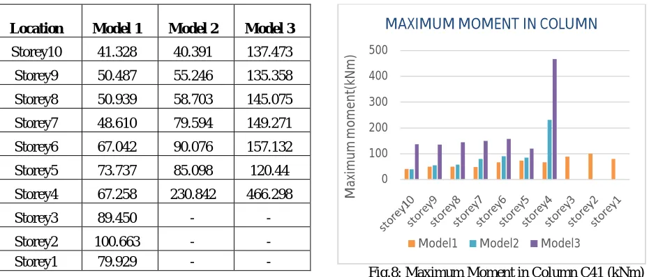
Table 2: Maximum Moment in Column C41 (kNm)
Location Model 1 Model 2 Model 3
Storey10 41.328 40.391 137.473
Storey9 50.487 55.246 135.358
Storey8 50.939 58.703 145.075
Storey7 48.610 79.594 149.271
Storey6 67.042 90.076 157.132
Storey5 73.737 85.098 120.44
Storey4 67.258 230.842 466.298
Storey3 89.450 - -
Storey2 100.663 - -
Storey1 79.929 - -
Fig.8: Maximum Moment in Column C41 (kNm)
B. SHEAR FORCEAND BENDING MOMENT IN BEAM
To study the variation of Shear Force and Bending Moment along continuous beam for regular and floating column building.
Table 3: Shear Force along Continuous Beam in X Direction (KN)
Label Location Model 1 Model 2 Model 3
B289 End-I 179.9975 478.9034 1401.234
B289 Middle 152.7365 220.619 956.132
B289 End-J 179.9013 693.8623 815.2497
B279 End-I 147.6673 693.8623 815.2497
B279 Middle 136.1831 844.3621 219.675
B279 End-J 147.4248 1059.226 905.8542
B290 End-I 183.2038 411.8336 905.8542
B290 Middle 156.0389 358.499 108.6005
B290 End-J 180.4701 303.8598 1439.223
B282 End-I 128.8272 76.0181 171.0321
B282 Middle 119.1249 66.2287 48.796
B282 End-J 129.2222 74.97 171.0321
B8 End-I 180.0474 248.7898 1445.099
B8 Middle 153.5645 358.2931 1006.685
B8 End-J 171.0321 392.1669 860.9132
B286 End-I 143.5698 1068.713 860.9132
B286 Middle 137.3118 909.32 219.675
B286 End-J 148.796 872.1816 854.41
B292 End-I 207.8003 872.1816 854.41
B292 Middle 180.6354 248.471 974.1244
B292 End-J 196.7875 470.3201 1385.319
0 100 200 300 400 500
M
ax
im
u
m
m
o
m
e
n
t(
kN
m
)
MAXIMUM MOMENT IN COLUMN
Fig.9: Shear Force along Continuous Beam in X Direction (KN)
Table 4: Bending Moment along Continuous Beam in X Direction (kNm)
Label Location Model 1 Model 2 Model 3
B289 End-I -174.97 -547.46 -2432.4
B289 Middle 66.23 228.557 51.8958
B289 End-J -174.79 740.017 2530.65
B279 End-I -66.495 744.336 2075.39
B279 Middle 18.059 -125.64 2057.24
B279 End-J -66.23 -672.57 2070.59
B290 End-I -180.61 -485.52 2467.22
B290 Middle 66.5541 12.7159 -103.65
B290 End-J -169.31 -144.13 -2626.4
B282 End-I -65.513 -17.17 -1432.1
B282 Middle 10.384 7.9486 -1320.7
B282 End-J -53.494 -16.349 -1390.5
B8 End-I -170.75 -115.85 -2667.6
B8 Middle 67.31 18.519 -163.64
B8 End-J -176.65 -479.18 2472.79
B286 End-I -63.228 -679.84 2085.23
B286 Middle 16.0234 -126.63 2061.15
B286 End-J -66.873 542.546 2061.86
B292 End-I -184.14 495.509 2455.78
B292 Middle 74.0467 239.95 -62.056
B292 End-J -183.15 -568.43 -2388.8
0 200 400 600 800 1000 1200 1400 1600 En d -I M id d le En d -J En d -I M id d le En d -J En d -I M id d le En d -J En d -I M id d le En d -J En d -I M id d le En d -J En d -I M id d le En d -J En d -I M id d le En d -J
B289 B289 B289 B279 B279 B279 B290 B290 B290 B282 B282 B282 B8 B8 B8 B286 B286 B286 B292 B292 B292
Sh ea r fo rc e (k N )
SHEAR FORCE ALONG CONTINUOUS BEAM
Fig.10:Bending Moment along Continuous Beam in X Direction (kNm)
C. BASE SHEAR
Base shear is an estimate of the maximum expected lateral force that will occur due to seismic ground motion at the base of a structure.
Table 5: Base Shear along X Direction (kN) Base Shear ,VB( )
Direction
model1 model2 model3
X
2899.146 2939.785 2959.865
Fig.11: Base Shear along X Direction (KN)
Table 6: Base Shear along Y Direction (kN) Base Shear ,VB( )
Direction
model1 model2 model3
Y
2877.015 2939.196 2947.561
Fig.12: : Base Shear along Y Direction (KN)
D. STORY DRIFT
It is the displacement of one level relative to the other level above or below. As per IS 1893 (Part 1):2002, the storey drift in any storey due to the minimum specified design lateral force, with partial load factor of 1.0, shall not exceed 0.004 times the storey height.
-3000 -2000 -1000 0 1000 2000 3000 En d -I M id d le En d
-J End-I
M id d le En d
-J End-I
M id d le En d
-J End-I
M id d le En d
-J End-I
M id d le En d
-J End-I
M id d le En d
-J End-I
M id d le En d -J B en d in g M o m en ts (k N m )
BENDING MOMENTS ALONG CONTINUOUS BEAM(kNm)
2899.146 2939.785 2959.865 2850 2900 2950 3000
model1 model2 model3
B as e sh ea r( kN )
Base Shear ,VB(
)
2877.015 2939.196 2947.561 2800 2850 2900 2950 3000
model1 model2 model3
B as e Sh ea r (k N
Table 7: Storey Drift along X Direction (m)
Location Model 1 Model 2 Model 3
Base 0 0 0
Storey1 0.000659 0.000323 0.000361
Storey2 0.001169 0.000531 0.000629
Storey3 0.001314 0.000542 0.000568
Storey4 0.001417 0.000889 0.000884
Storey5 0.001329 0.001078 0.001097
Storey6 0.001222 0.001029 0.001056
Storey7 0.001099 0.000934 0.000965
Storey8 0.001066 0.00092 0.000954
Storey9 0.000788 0.000691 0.000712
Storey10 0.000433 0.00038 0.000385
Table 8: Storey Drift along Y Direction (m)
Location Model 1 Model 2 Model 3
Base 0 0 0
Storey1 0.001113 0.000879 0.001013
Storey2 0.001819 0.001613 0.001764
Storey3 0.002199 0.001695 0.00149
Storey4 0.002296 0.002271 0.002032
Storey5 0.002126 0.002169 0.002165
Storey6 0.001946 0.001998 0.002022
Storey7 0.001744 0.001806 0.00184
Storey8 0.001602 0.001677 0.001711
Storey9 0.001192 0.001246 0.00127
Storey10 0.000623 0.000637 0.000659
Fig.13: Storey Drift along X Direction (m) Fig.14: Storey Drift along Y Direction (m)
E. STOREY STIFFNESS
The lateral stiffness Ks of a story is generally defined as the ratio of story shear to story drift, is affected by vertical distribution of lateral loads. The variation of storey stiffness due to floating column is studied.
Table 9: Storey Stiffness along X Direction (kN/m)
Location Model 1 Model 2 Model 3
Storey10 368497.3 401164.2 395245.4
Storey9 499577.1 551257 543827
Storey8 515266.6 565677.5 561788.3
Storey7 593377.3 652120.8 653265.7
Storey6 604456.3 670633.5 675137.7
Storey5 614544.5 713657.6 724642.9
Storey4 630763.3 988497.2 1044052
Storey3 740015 1917522 1930655
Storey2 888132.4 2072235 1644643
Storey1 1632171 3392042 2882617
Table 10: Storey Stiffness along Y Direction (kN/m)
Location Model 1 Model 2 Model 3
Storey10 289328.3 281087.8 262308.4
Storey9 343814.7 342427.6 331872.4
Storey8 345428.9 344485.6 337051.6
Storey7 371235.5 369698.7 362266.3
Storey6 373808.5 372207.4 365671.2
Storey5 376325.4 376202 373468.6
Storey4 381045 396351.9 436883.2
Storey3 432206.3 619689.8 707273.9
Storey2 574347.9 659002.4 611860.1
Storey1 964203.9 1236597 1098002
0 0.0005 0.001 0.0015
St
o
re
y
d
ri
ft
(
m
)
STOREY DRIFT ALONG X DIRECTION
model1 model2 model3
0 0.0005 0.001 0.0015 0.002 0.0025
St
o
re
y
d
ri
ft
(m
)
STOREY DRIFT ALONG Y DIRECION
Fig.15: Storey Stiffness along X Direction (kN/m) Fig.15: Storey Stiffness along Y Direction (kN/m)
VI. CONCLUSIONS
Axial force in floating column C41 decreases in the sequence of Model-1(1581.073), Model-2(967.8714), and
Model-3(746.6742).
Axial force in columns C3, C4, and C8 (column near to floating column) increases in the sequence of
Model-1(1590.591), Model-2(1841.472), and Model-3(2405.639).
Shear force in columns C3, C4, and C8 increases in the sequence of Mode-1(76.7703), Model-2(78.3307), and
Model-3(79.1892).
Bending moment in columns C3, C4, and C8 increases in the sequence of Mode-1(117.4862), Model-2(221.4957),
and Model-3(465.4106).
Regarding Shear force along Y direction for continuous beam (B326, B325, B18, B19, B20, B21, B22) in storey 3
the variations are less for Mode-1(122.4317), Model-2(121.2017), and Model-3(115.0948).
Regarding Hogging bending moment along Y direction for continuous beam (B326, B325, B18, B19, B20, B21,
B22) in storey 3 the variations are less for Mode-1(47.5551), Model-2(44.5558), and Model-3(42.5558).
Regarding Sagging bending moment along Y direction for continuous beam (B326, B325, B18, B19, B20, B21,
B22) in storey 3 the variations are less for Mode-1(109.482), Model-2(105.7006), and Model-3(97.2807).
For continuous beam (B289, B279, B290, B282, B8, B286, B392 of 1, B9, B290, B282, B8, B23 of
2, B36, B282, B37of 3) in storey 3 along X direction shear forces increases in the sequence of Model-1(179.9975), Model-2(478.9034), and Model-3(1401.234).
For continuous beam (B289, B279, B290, B282, B8, B286, B392 of 1, B9, B290, B282, B8, B23 of
Model-2, B36, B28Model-2, B37of Model-3) in storey 3 along X direction Hogging bending moment increases in the sequence of Model-1(174.97), Model-2(547.46), and Model-3(2432.4).
For continuous beam in storey 3 (B289, B279, B290, B282, B8, B286, B392 of Model-1, B9, B290, B282, B8,
B23 of Model-2, B36, B282, B37of Model-3) along X direction Sagging bending moment increases in the sequence of Model-1(74.0467), Model-2(744.336), and Model-3(2467).
Along X direction the storey maximum displacement decreases in the sequence of Mode-1(29.2556),
Model-3(20.8214), and Model-2(20.1868).
The storey Maximum displacement variations is less along Y direction for Mode-1(45.1357), Model-2(42.9485),
and Model-3(42.78627).
Along X direction the storey drift reduced in the sequence of Mode-1(0.000659), 3(0.000361), and
Model-2(0.000323).
0 500000 1000000 1500000 2000000 2500000 3000000 3500000 4000000
st
or
ey
s
ti
ff
n
es
s
(k
N
/m
)
STORY STIFFNES ALONG X DIRECTION
model1 model2 model3
0 200000 400000 600000 800000 1000000 1200000 1400000
St
or
ey
s
ti
ff
n
es
s(
kN
/m
)
Along Y direction the storey drift reduced in the sequence of Mode-1(0.000623), 3(0.000659), and Model-2(0.000637).
The floating column effect is more predominant when the span of beam and number of floating columns increases.
VII. REFERENCES
1. A.A.Vasilopoulos, Dimitri Baskos (2007), “seismic response of space steel frames using advanced method of analysis”. Steel and composite Structures 29(1):194-218.
2. Agarwal Pankaj, Shrikhande Manish (2009), “Earthquake resistant design of structures.
3. Balsamoa A, Colombo A, Manfredi G, Negro P &Prota P (2005), ”Seismic behavior of a full-scale RC frame repaired using CFRP laminates”. Engineering Structures 27 (2005) 769–780.
4. Bureau of Indian Standards: IS 1893(Part 1): 2002 Criteria for earthquake resistant Design of Structures :part-1 General provisions and Buildings , New Delhi India
5. Bureau of Indian Standards: IS 13920:1993.Ductile detailing of reinforced concrete structures subjected to seismic forces. 6. Chopra, Anil k. (1995), “Dynamics of structures”, Prentice Hall.
7. Nikhil Bandwal, AnantPande, VaishaliMendhe, AmrutaYadav(2014), “To Study Seismic Behaviour of RC Building with Floating Columns”, ISSN 2319-8885 Vol.03,Issue.08, May-2014, Pages:1593-1596
8. Niroomandia A., Maherib A, Maheric Mahmoud R., Mahini S.S. (2010) “Seismic performance of ordinary RC frames retrofitted at joints by FRP sheets”. Engineering Structures 32 (2010) 2326- 2336.
9. Ozyigit H. Alper(2009)“, “Linear vibrations of frames carrying a concentrated mass”, Mathematical and Computational Applications, Vol. 14, No. 3, pp. 197-206, 2009.
10. PrernaNautiyal, SaleemAkhtarandGeetaBatham “Seismic Response Evaluation of RC frame building with Floating Column considering different Soil Conditions”, International Journal of Current Engineering and Technology E-ISSN 2277 – 4106, P-ISSN 2347 - 5161 ©2014 INPRESSCO
11. R. Pranay, I.YaminiSreevalli, Er.Thota. Suneel Kumar, “Study and Comparison of Construction Sequence Analysis with Conventional Lumped Analysis Using E-tabs” Civil Engineering Systems and Sustainable Innovations ISBN: 978-93-83083-78-7