ISSN(Online): 2319-8753 ISSN (Print): 2347-6710
I
nternational
J
ournal of
I
nnovative
R
esearch in
S
cience,
E
ngineering and
T
echnology
(An ISO 3297: 2007 Certified Organization)
Website: www.ijirset.com
Vol. 6, Issue 9, September 2017
Doubly Fed Induction Machine-Based Wind
Generator Transient Stability Improvement
Using Bridge-Type Fault Current Limiter
Kamsali.Mounika1, S.Imran Khan2, D.Mahesh Kumar3
M.Tech Student, Dept of EEE, Ananthalakshmi Institute of Technology and Sciences, AP, India 1 Assistant Professor, Dept. of EEE Ananthalakshmi Institute of Technology and Sciences, AP, India2 Associate Professor & HOD, Dept. of EEE, Ananthalakshmi Institute of Technology and Sciences, AP, India 3
ABSTRACT: In this paper Transient stability is a major sympathy toward doubly fed induction machine (DFIM).A
DFIM-based wind generator is promptly influenced by shortcomings at the network side as its stator windings are interfaced to grid. Be that as it may, the wind generators need to stay connected and proceed with operation during flaws at the grid side as indicated by the network code prerequisites. Along these lines, it is imperative to improve the transient soundness of the DFIM-based wind generators. To accomplish upgraded transient steadiness of the DFIM, a bridge type fault current limiter (BFCL) is proposed in this study.
KEYWORDS: BFCL, Doubly Fed Induction Machine (DFIM, Rotor-Side Converter (RSC) and Grid Side Converter
(GSC)..
I. INTRODUCTION
Technological advancement and industrialization has brought the expansion up in electrical power demand all around the globe. Quick fatigue and restricted store of fossil powers, escalation of natural concerns have made it dire to look for alternative energy sources and to devise enhanced techniques for abusing renewable energy sources. Among the available renewable energy sources, wind energy is the quickest developing and most noticeable choice to create electric power because of its zero fuel cost, no carbon discharge, lower maintenance, and cleaner, less expensive and renewable nature. It is assessed that around 10% of worldwide power interest will be supplied from the wind energy by the year 2020. Because of adaptability in operation and upgraded highlights like higher output power, higher proficiency, enhanced power quality, variable pace operation, lower mechanical weight on turbine subsequently bring down support, decoupled control of the active and reactive power, the variable rate wind generators are getting to be favored decision for new establishments and drawing higher consideration than the conventional impelling machine-based altered rate wind generators. Lower cost, sturdiness, basic structure, probability to cover an extensive variety of wind rate, in part evaluated variable frequency ac/dc/air conditioning converter and lower switching loss have made the doubly sustained incitement machine (DFIM) a better decision over the other wind generator choices.
Contrasted with variable pace wind generators having full appraised converter, the DFIM is more powerless against grid shortcoming or unsettling influences from the soundness point of view, as its stator windings are straight forwardly associated with system while rotor windings are interfaced to
ISSN(Online): 2319-8753 ISSN (Print): 2347-6710
I
nternational
J
ournal of
I
nnovative
R
esearch in
S
cience,
E
ngineering and
T
echnology
(An ISO 3297: 2007 Certified Organization)
Website: www.ijirset.com
Vol. 6, Issue 9, September 2017
channels. Energy stockpiling systems like flywheel energy stockpiling, superconducting attractive energy stockpiling and superconducting deficiency current limiter are additionally proposed, however the high establishment cost counterbalances their great execution.
The bridge type fault current limiter (BFCL) is another method with promising applications in power systems and issue ride through ability improvement of altered speed wind turbine generators. Be that as it may, the BFCL is never connected to improve the transient solidness of DFIM-based wind generators. In this study, execution of the BFCL on upgrading the transient stability of the DFIM in wind energy application is researched. The effectiveness of the proposed BFCL is shown through a test wind energy conversion system. The system comprises of a wind turbine furnished with a DFIM, a transformer and the double circuit transmission lines connected with the boundless bus. Transitory symmetrical and unsymmetrical shortcomings were connected at the most powerless purpose of the
system. Where ωr is the angular mechanical speed. The wind turbine
Fig: 1 Basic diagram of the DFIM with the test system.
II. WIND TURBINE AND DFIM MODELING
A solitary mass system is considered for the demonstrating of the wind turbine. The turbine mechanical part progression is dismissed because of little span of the considered deficiencies. The DFIM itself is fundamentally an actuation generator with the stator windings directly connected with grid and open rotor windings connected with the grid through the ac/dc/ac converter as appeared in Fig. 1. Fig. 1 likewise demonstrates the one line graph of the test system model alongside the line parameters. A 2-MW DFIM is connected with the point of common coupling (PCC) through a phase up transformer. The PCC is connected with network through double circuit transmission line. The BFCL is connected in series with one of the transmission lines to secure it as appeared in Fig. 1. The SDBR is likewise connected at the same point in comparative style. Displaying of the wind turbine, the DFIM and the converter controllers are outlined in the consequent segments.
A. Wind Turbine Modeling
The displaying of the wind turbine relies on upon different physical and geometrical angles. For effortlessness, considering the electrical conduct of the system just, a streamlined strategy for displaying the wind turbine is typically utilized. The normally utilized scientific connection for the mechanical power tackled from the wind, can be communicated as takes after
ISSN(Online): 2319-8753 ISSN (Print): 2347-6710
I
nternational
J
ournal of
I
nnovative
R
esearch in
S
cience,
E
ngineering and
T
echnology
(An ISO 3297: 2007 Certified Organization)
Website: www.ijirset.com
Vol. 6, Issue 9, September 2017
Where Pw is the extracted power from the wind, ρ is the air density, R is the blade radius, Vw is the wind velocity, and Cp is the power coefficient which is a function of both the tip speed ratio λ, and the blade pitch angle β and it is
given by
---(2)
---(3)
Where ωr is the angular mechanical speed. The wind turbine parameters used in this study.
B. DFIM Modeling
Many works like have portrayed the demonstrating of the DFIM. The Park's change model, which is basically the fifth-order two-axis representation is displayed the DFIM. A synchronously turning d − q reference edge is utilized
with its d-hub adjusted to the stator flux. A decoupled control between the rotor excitation current and the electrical torque is gotten. Thusly, the reference angle is turning with the same pace as the stator flux.
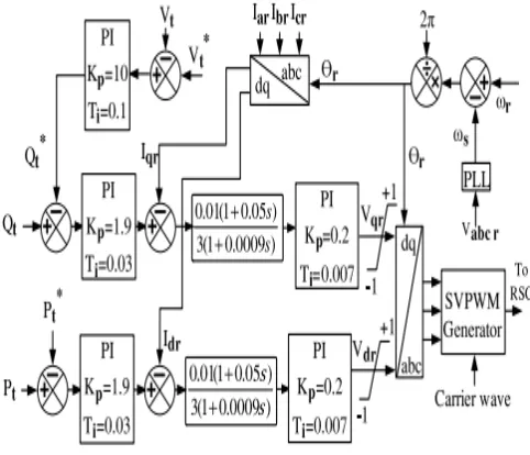
C. RSC Controller
The RSC is a two-level, six-beat, Insulated gate bipolar transistor (IGBT) [CM200HG-130H] based full extension power electronic ac/dc converter that couples the rotor side to the dc link. The RSC controller takes the terminal active power Pt, the reactive power Qt and the terminal voltage Vt as inputs and controls the output active and reactive power. It utilizes the proportional integral (PI) controllers to deliver fitting three phase (SVPWM) signal generator square, with the goal that it can create beats for the IGBT switches of the RSC. The Park's change is utilized to change over three phase amounts into proportional d − q parts and the other way around. The slip edge is produced by looking at the rotor position and the terminal voltage angle with the assistance of the phase-locked loop (PLL), and the slip is utilized as change point as a part of the Park's change square. Amounts with "*" referee to reference value as appeared in Fig. 2.
ISSN(Online): 2319-8753 ISSN (Print): 2347-6710
I
nternational
J
ournal of
I
nnovative
R
esearch in
S
cience,
E
ngineering and
T
echnology
(An ISO 3297: 2007 Certified Organization)
Website: www.ijirset.com
Vol. 6, Issue 9, September 2017
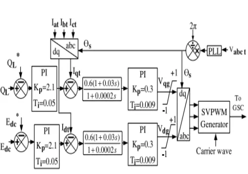
Fig. 3. GSC controller.
reference signal for space vector pulse width modulation (SVPWM) signal generator block, so that it can generate pulses for the IGBT switches of the RSC [27]. The Park’s transformation is used to convert three phase quantities into equivalent d−q components and vice versa. The slip angle is generated by comparing the rotor position and the terminal voltage angle with the help of the phase-locked loop (PLL), and the slip is used as transformation angle in the Park’s transformation block. Quantities with “*” refer to reference value as shown in Fig. 2.
D. GSC Controller
The GSC also contains a two-level, six-pulse, IGBT [CM200HG-130H] based full bridge power electronic ac/dc converter with the dc side connected to the dc link and the ac side interfaced to the grid. This converter essentially helps maintain a constant power factor at the connection point. It is
important to choose an appropriate switching frequency to keep the harmonics to the minimum level. A frequency of 1650 Hz is chosen as it is an odd multiple of the third harmonic and can minimize up to thirteenth harmonics. The GSC controller scheme is given in Fig. 3. It takes the dc link voltage Edc and the rotor line reactive power QL as inputs and produces the necessary outputs so that the SVPWM pulse generator can generate required pulses for the GSC converter. Also, by maintaining a constant dc-link voltage, the controller ensures the energy balance on the both sides of the dc link.
III. BFCL
BFCL Configuration
ISSN(Online): 2319-8753 ISSN (Print): 2347-6710
I
nternational
J
ournal of
I
nnovative
R
esearch in
S
cience,
E
ngineering and
T
echnology
(An ISO 3297: 2007 Certified Organization)
Website: www.ijirset.com
Vol. 6, Issue 9, September 2017
Fig. 5. BFCL controller
BFCL Operation
During normal operating condition of the system, the IGBT switch in the bridge part remains closed. For one half cycle of
electrical frequency, theD1-Ldc-Rdc-D4 path carries the line current and for the other half it is carried byD2-Ldc-Rdc-D3.
So, the current through Ldc, flows in the same direction and this current is the dc current idc. Ldc is charged to the peak current and offers no impedance to idc. The dc reactor inherited resistance, the IGBT turn-on resistance and the diode forward voltage drop cause some voltage drop, but this voltage drop is quite negligible compared to line drop and has ignorable significance. So the bridge has no impact on normal or steady state operation.
IV. SDBR
In this study, so as to exhibit the effectiveness of the proposed BFCL arrangement, its execution is contrasted and that of the SDBR as shown in Fig.6. The SDBR is a demonstrated innovation, and past studies demonstrated that it can upgrade transient strength and enhance issue ride through ability of the wind generator systems.
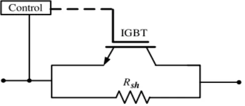
SDBR Configuration
The SDBR is modeled by arranging a resistor with a parallel switch as shown in Fig. 6. This study considers this switch to be the IGBT based, due to its fast response and modular design.
ISSN(Online): 2319-8753 ISSN (Print): 2347-6710
I
nternational
J
ournal of
I
nnovative
R
esearch in
S
cience,
E
ngineering and
T
echnology
(An ISO 3297: 2007 Certified Organization)
Website: www.ijirset.com
Vol. 6, Issue 9, September 2017
B. SDBR Operation
During the normal condition, the SDBR would operate with the IGBT switch closed. The line current will flow through the
IGBT switches bypassing the braking resistors. At the event of fault, the line currents tend to rise very sharply. The shunt resistor will be dynamically inserted into the network by opening the IGBT switch. The fault current will then flow through the inserted resistor and the resistor will continue to be in the circuit until a desired voltage Vref is achieved at PCC. As Vpcc passes Vref, the IGBT will be closed and the circuit will return to its normal state.
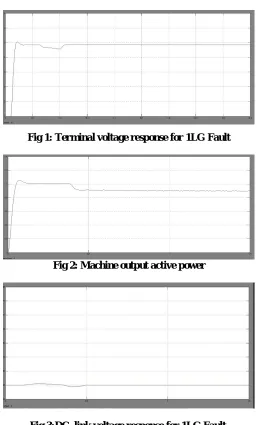
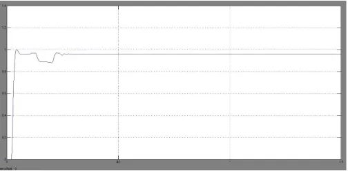
D. BFCL 1LG
Fig 1: Terminal voltage response for 1LG Fault
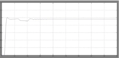
Fig 2: Machine output active power
ISSN(Online): 2319-8753 ISSN (Print): 2347-6710
I
nternational
J
ournal of
I
nnovative
R
esearch in
S
cience,
E
ngineering and
T
echnology
(An ISO 3297: 2007 Certified Organization)
Website: www.ijirset.com
Vol. 6, Issue 9, September 2017
Fig 5: speed response for single LG Fault
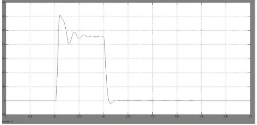
E. BFCL 3LG:
Fig 6 :Active power consumed in BFCL for 3LG Fault
ISSN(Online): 2319-8753 ISSN (Print): 2347-6710
I
nternational
J
ournal of
I
nnovative
R
esearch in
S
cience,
E
ngineering and
T
echnology
(An ISO 3297: 2007 Certified Organization)
Website: www.ijirset.com
Vol. 6, Issue 9, September 2017
Fig 8: DC link voltage response for 3LG fault
Fig 9: speed response for 3LG Fault
F. BFCL FOR 3LG USING FUZZY
ISSN(Online): 2319-8753 ISSN (Print): 2347-6710
I
nternational
J
ournal of
I
nnovative
R
esearch in
S
cience,
E
ngineering and
T
echnology
(An ISO 3297: 2007 Certified Organization)
Website: www.ijirset.com
Vol. 6, Issue 9, September 2017
Fig 11:Terminal voltage response for 3LG Fault using fuzzy
Fig 12: DC Link voltage response for 3LG Fault using fuzzy
Fig 13: speed response for 3LG Fault using fuzzy
VII. CONCLUSION
The application of the BFCL to enhance the transient stability of DFIM is proposed in this paper. The performance of the proposed BFCL is compared with that of the SDBR. From the simulation results, the following points are noteworthy.
1) The BFCL is a very effective means to enhance the transient stability of the DFIM-based variable speed wind generator.
ISSN(Online): 2319-8753 ISSN (Print): 2347-6710
I
nternational
J
ournal of
I
nnovative
R
esearch in
S
cience,
E
ngineering and
T
echnology
(An ISO 3297: 2007 Certified Organization)
Website: www.ijirset.com
Vol. 6, Issue 9, September 2017
except cost, as seen from graphical and numerical results. In our future study, a high capacity variable speed wind farm connected to a large power system will be considered. Also, a prototype of the BFCL will be tested with low voltage and little power test bench to check the effectiveness. Furthermore, an optimal design of the BFCL will be developed considering variable values of the shunt impedance.
REFERENCES
[1] B. Singh, P. Jayaprakash, T. R. Somayajulu, and D. P.Kothari, “Reducedrating VSC with a zig-zag transformer for current compensationin a
three-phase four-wire distribution system,” IEEE Trans. PowerDel., vol. 24, no. 1, pp. 249– 259, Jan. 2009.
[2] R. M. Ciric, L. F. Ochoa, A. Padilla-Feltrin, and H. Nouri, “Fault analysisin four-wire distribution networks,”Proc. Inst. Elect. Eng., Gen.,Transm. Distrib., vol. 152, no. 6, pp. 977–982, 2005.
[3] J. C. Meza and A. H. Samra, “Zero-sequence harmonics current minimizationusing zero-blocking reactor and zig-zag transformer,” in
Proc.IEEE DRPT, 2008, pp. 1758–1764.
[4] H. L. Jou, J. C.Wu,K.D.Wu,W. J. Chiang, andY. H. Chen, “Analysisof zig-zag transformer applying in the three-phase four-wire
distributionpower system,” IEEE Trans. Power Del., vol. 20, no. 2, pt. 1, pp.1168–1178, Apr. 2005.
[5] S. Choi and M. Jang, “Analysis and control of a single-phase-inverterzigzag-transformer hybrid neutral-current suppressor in
three-phasefour-wire systems,” IEEE Trans. Ind. Electron., vol. 54, no. 4, pp.2201–2208, Aug. 2007
[6] F. Mei and B. C. Pal, “Modelling of doubly-fed induction generator forpower system stability study,” in Proc. IEEE Power Energy Soc.
Gen.Meeting, Jul. 2008, pp. 1–8.
[7] G. D. Marques, “Active stabilization method for the doubly-fed inductiongenerator using a quadrature inner control loop,” in Proc. Int.
Conf. PowerEng. Energy Elect. Drives, Apr. 2007, pp. 765–768.
[8] G. D. Marques, “Comparison of active stabilization methods for the doubly-fed induction generator—Quadrature versus direct inner
control loops,” in Proc. Eur. Conf. Power Electron. Appl., Sep. 2007, pp. 1–10.
[9] P.La Seta and P. Schegner, “Comparison of stabilizing methods for doublyfed induction generators for wind turbines,” in Proc. Int. Conf.
Futur.
[10] Power Syst., Nov. 2005, Paper W045, Conference CDROM. P. La Seta and P. Schegner, “New control scheme for doubly-fed induction
[11] generators to improve transient stability,” in Proc. IEEE Power Eng. Soc.Gen. Meeting, Jun. 2007, pp. 1–10.
[12] F. K. A. Lima, A. Luna, P. Rodriguez, E. H. Watanabe, and F. Blaabjerg,“Rotor voltage dynamics in the doubly fed induction generator
during grid faults,” IEEE Trans. Power Electron., vol. 25, no. 1, pp. 118–130, Jan. 2010.
[13] J. P. A. Vieira, M. V. A. Nunes, and U. H. Bezerra, “Improving the transient performance of doubly fed induction generators when
submitted.
BIOGRAPHY
1. S.Imran khan working asAssistant Professor in Anantha Lakshmi Institute of Technology and sciences Anantapur, Andhra Pradesh. He completed his M.Tech in 2014.He is interested in electrical Power systems and electrical machines domains.
2. Kamsali Mounika completed B.Tech. in SRIT in 2015.Now she is pursuing M.Tech. in ALTS. She is interested in power systems domain.