Robust Control for Repressing Circulating
Current in Parallel Solid State Transformer
based on Impedance Matching Technique
Kavipriya.J1, Lavanya.M2
P.G. Student, Department of EEE, Kingston Engineering College, Vellore, Tamilnadu, India1
Assistant Professor, Department of EEE, Kingston Engineering College, Vellore, Tamilnadu, India2
ABSTRACT: In renewable power system, the excess residual power after met with the demand has to be conserved using proper power electronic devices and storage systems. In order to satisfy the increased demand using the renewable sources, we can use more number of units in parallel instead of bigger power devices. If the converters are used in parallel, then the switching loss and delay time will be high, which affects the quality of the output power. To overcome this problem, solid state transformer has been proposed using high frequency transformer. SST provides more advantages than conventional transformer in the regard of bidirectional power flow. But the parallel operation in turn may cause the circulating current to flow in the system because of the mismatched impedances. This circulating current in turn may cause the real power swings and absorbs more power from the supply. The proposed control scheme suppresses the circulating current among parallel connection of SST using impedance control by generating virtual impedance. The simulation results with various loading conditions are presented to show the reduced circulating current and it provides improved power sharing among the parallel SSTs.
KEYWORDS: Solid state transformer (SST), circulating current, virtual impedance control, Dual active bridge (DAB).
I. INTRODUCTION
enewable energy sources plays a vital role in supplying power to the load to persuade the demand starting from the grid side and the reverse may happens if the surplus power is delivered to the grid. Power generated from the grid undergoes various conversion stages to get the required voltage level, which is suitable to the load. In this paper, FREEDM system is considered which consists of distributed energy sources and storage devices. It has many positive features both in its structural and functional configuration when compared to conventional distribution system in terms of fault detecting and islanding, thereby safeguards the power system equipments as in [1].
Intelligent Energy Management is provided so that the fault can be easily identified and rapid fault clearing is done due to the data communication. This type of protection offers protection even for fault current less than 2pu, which the traditional method fails to do as described in [2].
In these type of devices also the excess power after the demand satisfaction has to be fed back to the grid for future use. For that purpose converters are used, but results in more switching loss due to sudden switching of the converter. Thus, the harmonic resonance occurs and power shared unequally. The converters used in this configuration do not provide much voltage transformation and hence the interfacing of various levels of voltage becomes the major problem as in [3]. For this purpose, transformers were used. But the conventional distribution side transformer so far used requires periodical maintenance, core saturation which leads to large inrush current flow. This in turn may cause the windings damage and results in poor voltage regulation. In order to address these problems, SSTs are used which is also known as electronic transformer shown in (X.L.Mao et al.p1127)[4] .
SST structure consists of high frequency transformer, dc-ac-dc converter to provide the smooth transition of voltage by frequency isolation, in the range of few hundred KHz as in [5]. High frequency transformer is used to provide
galvanic isolation and to supply the larger rating of power. Instead of using a single transformer with large power rating it is preferable to use more number of smaller units in parallel configuration. For parallel connection it must be ensured that the following conditions has to be satisfied which includes same voltage ratio, same percentage impedance, same polarity, same KVA ratings and same phase sequence. If the impedance differs for the same voltage level then varying amount of current flows through the device due to mismatched impedances, which is the circulating current. This circulating current has to be suppressed to provide accurate power sharing. Virtual impedance control is proposed to reduce the circulating current [6].
This paper is organised as follows. In Section II, SST structure is shown with DAB configuration and it describes the formation of circulating current between the parallel connecting devices. Control strategy with the reference voltage generation is presented in Section III. The simulation results are shown in Section IV.
II. DESIGN OF SOLID STATE TRANSFORMER
Solid state transformer refers to the electronic components, devices and system entirely based on semiconductor devices. SST is used to achieve the voltage transformation by medium to high frequency isolation, to reduce the volume and weight compared to the traditional distribution transformer. Priorly, vacuum tube technology is used. The
60Hz AC/AC transformers are heavy, bulky and subjected to magnetic saturation due to dc current components and
results in overheating due to the flow of harmonic current. A solid state transformer based on switched mode technology would minimise these problems and in turn provides the following additional features. It can be smaller in size so that it provides thermal management and be insensitive to dc current components. Such a transformer would also allow electronic voltage and current wave shaping.
A. SST model
The configuration of SST involves dual active bridge, high frequency transformer and the power electronic devices. The basic structure of SST is depicted in Fig.1.Galvanic isolation is provided through the high frequency transformer. The grid voltage is converted into a higher frequency AC voltage through the use of power-electronic based converter before to be applied to the primary side of the HF transformer. The reverse will happen on the load side of HF transformer so that the required output is obtained at the load side.
converter demodulates the square wave and sends it to another inverter which produces the required ac to the load. It helps to provide reduced peak inverse voltage and improved utilisation of the supply transformer.
2) High frequency transformer: In high frequency transformer the input voltage wave applied and the operating frequency is in the range of few hundred KHz. Mostly used in energy efficient drives and switched mode power supplies. It requires shell type core transformer and provides electrical isolation between the ground path and the electrical device, to match the voltage level of the load and the source. It offers cheap cost and simple to install but requires periodical checking for failure.
3) Functionalities: SST provides on-state reactive power support and if the input voltage fluctuates then also the output voltage level is maintained constant by the energy buffer. The device is insensitive to harmonics; prevents load disruptions; no requirement of oil; fast fault detection and islanding; has dc link so that does not affect from sag/swell, provides bidirectional power flow, management of distributed storage devices and dc bus.
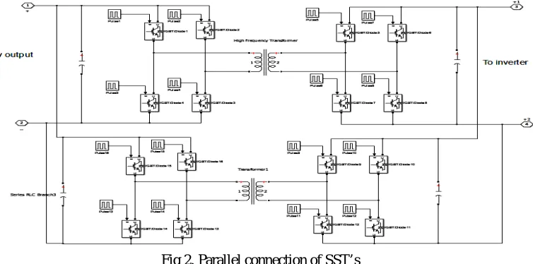
B. Parallel operation of sst’s
It is economical to install more number of smaller units in parallel than a single larger unit in order to maximise the efficiency and reliability. Even if one of the units is shut down for a certain period or for the maintenance purpose then, the remaining units will operate to satisfy the demand without any interruption, which is not possible in series configuration.
Fig 2. Parallel connection of SST’s
Similarly, parallel connection of transformer as shown in Fig.2. requires some of the conditions to be satisfied such as it should possess the same voltage ratio, same percentage impedance and same polarity as well as phase sequence in both the devices to be connected in parallel. Thus the above said conditions must be strictly followed for parallel operation of transformers but it is difficult to achieve the identical percentage impedance, as the transformer run in parallel may not have the exactly same percentage impedance[4]. Because of this, impedance mismatch occur which results in large circulating current. This in turn affects the efficient operation of solid state transformer.
C. Circulating current
When the transformer are connected in parallel, due to differences in the manufacturing tolerances by 5-10% and for the same voltage and varying impedance ,there occurs two different current flows through the device as shown in Fig.3.
(GUERRERO et al.p1127)[6]. This current is known to be the circulating current and this are produced due to magnetic flux
kind of current which usually affects the system performance, reduces the efficient power transfer, produces unequal load sharing, and produces noise which affects the quality of the output.
Fig.3. circulating current between two SST
III.CONTROL STRATEGY
The control strategy presented here is the virtual impedance controller to reduce the circulating current. Virtual impedance control is used in the proposed method, by which the current is given as the feedback, based on the concept of impedance matching to generate the PWM pulses for the inverter.
A. Virtual impedance control
In virtual impedance control, for the same supply voltage the current will differs. It is preferred to generate a reference voltage as shown fig .4.[5] The reference voltage is generated based on the supply voltage, from which the current will be generated and is given as feedback to generate the virtual impedance. Form the mathematical model the equations are developed in such a way to formulate the reference voltage using the virtual impedance.
The current equations are given as
= 1 (1)
= 2 (2)
For the same reference voltage, due to varying impedances z1 and z2, different current flows through the device. The circulating current between two sst’s as described in figure is represented by,
= 1− 2 (3)
This circulating current has been nullified by making the impedance of the two transformer to produce the same current in both the devices as in fig.4.(Guerrero,et.al.p 159)[6].Other approach is to generate the reference voltage based on these impedance values and this current is fed back to the impedance block, so that the pulses are generated in such a way that it can suppress the circulating current.
Fig.4. Virtual impedance control and reference voltage generation
The impedance considered is purely inductive in nature and it can be said that the increase in the inductance values not only ensures system stability, also suppress the circulating current, accurate power sharing but results in excessive voltage drop[8][9]. Freedm system is sensitive to voltage deviation and hence it is necessary to maintain the fluctuation within +2% to -2% of the rated value.
IV.SIMULATION RESULTS
In this section, parallel configuration of SST with proposed control scheme is implemented to show the validity of the anticipated method using MATLAB/SIMULINK software package. Here the controller is presented by varying the output voltage bandwidth to match with the impedance. The controller part consists of voltage and current control loop, real and reactive power calculation, droop control and the virtual output impedance calculation loop. The circulating cuurent is measured with and without controller part with the solar input and frequency of about 50Hz;angular frequency of 314rad/sec.
Fig.5. circulating current without controller Fig.6. Circulating current with controller
Fig.7. Reference voltage
This approach receives less distortion when compared to the system without any controller and fig.8. shows the virtual impedance calulcated level.
Fig.8. virtual impedance
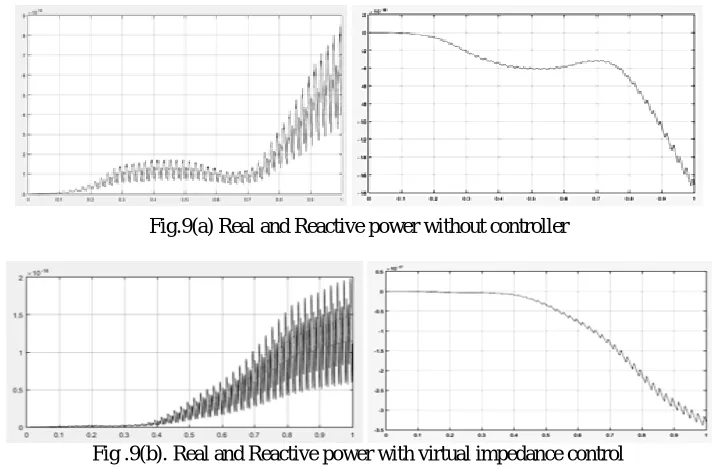
The real and reactive power is calculated to probe the order of power swings and the efficiency of the power transfer and it shows the power swings is mainly due to the resultant of varying inputs include the current for the same grid voltage.
Fig.9(a) Real and Reactive power without controller
From this, the system is capable to deliver excellent power sharing under steady state and also for varying load conditions, so that the output will be continuous. Similarly it is observed from the diagram that the reduction in circulating current results in improved power output and this robust control enables SSTs to share the load in the light of their nominal capacity and substantially reduce the circulating current among them.
V. CONCLUSION
The proposed controller impact in the system performance has been analysed. The obtained simulation results show that how this approach achieves less output voltage distortion with reduced circulating current than the conventional control method. The feedback of the circulating current makes the virtual impedance to match with the system impedance to nullify the error to zero. With this controller, the system is capable to deliver high quality power with reduced power swings even in the presence of nonlinear loads. Also it provides good power sharing and provides fast transient response when sharing common loads.
REFERENCES
[1] A. Q. Huang, M. L. Crow, G. T. Heydt, J. P. Zheng, and S. J. Dale, “The Future Renewable Electric Energy Delivery and Management (FREEDM) system: The energy internet,” Proc. IEEE, vol. 99, no. 1, pp. 133–148, Jan. 2011.
[2] E. Ronan, S. Sudhoff, S. Glover, and D. Galloway, BA power electronic based distribution transformer, IEEE Trans. Power Delivery, vol. 17, no. 2, pp. 537–543,Apr. 2002
[3] Kang, M., Enjeti, P., and I. Pitel, “Analysis and Design of Electronic Transformers for Electric Power Distribution System,” in IEEE Transactions on Power Electronics, Nov. 1999
[4] X. L. Mao, S. Falcones, and R. Ayyanar, “Energy-based control design for a solid state transformer,” in Proc. IEEE Power Energy Soc. Gen.Meeting, Minneapolis, MN, USA, Jul. 2010, pp. 1–6.
[5] J. M. Guerrero, J. C. Vasquez, J. Matas, L. G. de Vicuna, and M. Castilla,“Hierarchical control of droop-controlled AC and DC microgrids— A general approach toward standardization,” IEEE Trans. Ind. Electron.,vol. 58, no. 1, pp. 158–172, Jan. 2011
[6] J. M. Guerrero, L. Garcia de Vicuna, J. Matas, M. Castilla, and J. Miret,“Output impedance design of parallel-connected UPS inverters with wireless load-sharing control,” IEEE Trans. Ind. Electron., vol. 52, no. 4,pp. 1126–1135, Aug. 2005.
[7] J. W. He and Y. W. Li, “Analysis, design, and implementation of virtual impedance for power electronics interfaced distributed generation,”IEEE Trans. Ind. Appl., vol. 47, no. 6, pp. 2525–2538, Nov. 2011.