The Study on Effect of Process Parameters on
Weld Deposits in Pulsed Gas Metal Arc
Welding
D.Sindhu1, M.Ruban2
PG Scholar, Department of Mechanical Engineering, Computer Integrated Manufacturing School of Engineering, Vels
University, Chennai, India1
Assistant Professor, Department of Mechanical Engineering, Computer Integrated Manufacturing School of
Engineering, Vels University, Chennai, India2
ABSTRACT: Pulsed gas metal arc welding is one of the most widely used processes in the industry. It offers spray metal transfer at low average currents, high metal deposition rate, versatility, less distortion, and the ability to be used in automated robotic welding systems. The weld bead plays an important role in determining the mechanical properties of the weld. Its geometric parameters, viz., width, reinforcement height, and penetration, are decided according to the welding process parameters, such as welding voltage, welding speed, pulse current magnitude, frequency (cycle time), etc. Therefore, to produce good weld bead geometry, it is important to set the proper welding process parameters. In this project, mathematical models that correlate welding process parameters to weld bead geometry are developed with experimental investigation. Taguchi methods are applied to plan the experiments. Five process parameters, viz., welding speed, plate thickness, pulse frequency, pulse current magnitude, welding voltage etc and base material as stainless steel (SS grade 410) are selected to develop the models using multiple regression analysis. The models developed were checked for their adequacy. Results of confirmation experiments show that the models can predict the bead geometry with reasonable accuracy
1. INTRODUCTION
1.1 METAL INERT GAS WELDING
MIG (Metal Inert Gas) welding, also known as MAG (Metal Active Gas) and in the USA as GMAW (Gas Metal Arc Welding), is a welding process that is now widely used for welding a variety of materials, ferrous and non ferrous. The essential feature of the process is the small diameter electrode wire, which is fed continuously into the arc from a coil. As a result this process can produce quick and neat welds over a wide range of joints.
1.2 MIG WELDING EQUIPMENT & ACCESSORIES
1.2.1 MIG WELDING ACCESSORIES – BASIC OVERVIEW OF WHAT EQUIPMENT YOU NEED TO MIG WELD
MIG welding requires the right equipment unless you have a single purpose MIG welding machine. This page is an overview of the equipment needed if you are using a power supply and need or want the bells and whistles.
MIG welders are a CV or constant voltage power supply. They are just the power supply that creates the voltage, amperage and polarity needed to MIG weld but nothing more. Once you have a power supply you will then need:
• Wire Feeder • MIG Gun • Gas Regulator
• Hoses and Ground Clamp • Add on Wire Feed System • Suite Case Wire Feed System • Spool Feed Guns
• Add on Wire Feed Systems
Add on wire feeders are simply a wire feeder that is put on top or on the side of a power supply. These are most commonly found on factory floors and production shops that require high duty cycles and lots of voltage to run welds on heavy plate. This is not for your everyday welding and is more of a specialty item more than anything else. Add on wire feed systems are used for high production welding and have the fastest of the wire feed speeds.
1.3 SUITE CASE WIRE FEED SYSTEMS
Suite case wire feed systems are used for most multi process welders. You simply plug them into the power supply, hook up the gas and put in the MIG wire. They are great and I have had some real good personal experiences with these. They come in the form of a suite case with three cords hanging out of the back (power cord, remote wire, shielding gas hose) and a MIG gun attached to the front. They are water proof and run flawlessly in some crazy conditions. I liked the enclosed case that keeps dust and debris out of the wire. Another good point about these wire feeders is that the cable is short so running wire like stainless steel is not an issue. These suite case wire feeders are used in most shipyards and to be honest they work better then all of the other feeders I have ever used!
SPOOL FEED GUNS
Spool feed MIG guns are the most trouble free of the MIG guns available! They are not the cheapest or most efficient to use. These are the choice of aluminum MIG welders because of the short distance the wire needs to travel to the joint from the spool. The down side is the size of the wire that can fit into the gun. Not very big at a 4” inch max spool but it is as trouble free as it can get.
MIG GUNS OR TORCHES
The MIG gun is what MIG welding is all about! It is all about squeezing the trigger and getting everything to work properly to produce a weld. There are three choices for MIG guns and they are:
• The Standard MIG Guns • Spool Feed MIG Guns • Push Pull MIG Guns
These are just the basics types of MIG welding equipment and there are many other types of welder accessories out there.
THE STANDARD MIG GUNS
The standard MIG gun is nothing more than a cable with a gas feed system that has a remote wire that is connected to the trigger. It is a basic piece of equipment that works well in most cases except for soft filler metals like aluminum.
SPOOL FEED MIG GUNS
PUSH PULL MIG GUNS
The push pull feed system is great for either stainless steel, aluminum welding or if you need a lot of liner/cord between you and the MIG welding machine. The push pull system is most commonly used in welding aluminum. The push pull wire feed systems are used on factory floors and anywhere that lots of aluminum/stainless steel MIG welding is needed. My first welding job in a factory was using a Cobra Push Pull Feed system welding aluminum. It works great as long as everything is set right. Setting everything right is another story!
1.5. CHARACTERISTICS OF THE MIG WELDING PROCESS 1.5.1 MIG
Uses a consumable wire electrode during the welding process that is fed from a spool, • Provides a uniform weld bead,
• Produces a slag-free weld bead,
Uses a shielding gas, usually – argon, argon - 1 to 5% oxygen, argon - 3 to 25% CO2 and a combination argon/helium gas,
• Is considered a semi-automatic welding process, • Allows welding in all positions,
• Requires less operator skill than TIG welding, • Allows long welds to be made without starts or stops, • Needs little cleanup.
•
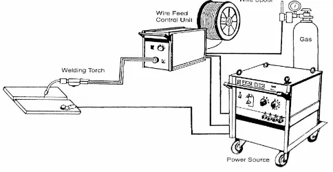
The illustration that follows provides a look at a typical MIG welding process showing an arc that is formed between the wire electrode and the workpiece. During the MIG welding process, the electrode melts within the arc and becomes deposited as filler material. The shielding gas that is used prevents atmospheric contamination from atmospheric contamination and protects the weld during solidification. The shielding gas also assists with stabilizing the arc which provides a smooth transfer of metal from the weld wire to the molten weld pool.
Versatility is the major benefit of the MIG welding process. It is capable of joining most types of metals and it can be performed in most positions, even though flat horizontal is most optimum.
The most common welds are illustrated below. They include the: • lap joint
• butt joint • T-joint, and the • edge joint
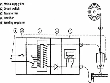
Figure 1.2 Power source
dioxide is most often used to weld carbon and low alloy steels. Magnesium and cast iron are other metals commonly welded used the MIG process
Related metal fabricating services, tips and facts: • Welding services
• TIG welding
• Stick or MSAW welding
POWER SOURCE
MIG welding is carried out on DC electrode (welding wire) positive polarity a(DCEP). However DCEN is used (for higher burn off rate) with certain self shielding and gas shield cored wires. DC output power sources are of a transformer-rectifier design, with a flat characteristic (constant voltage power source). The most common type of power source used for this process is the switched primary transformer rectifier with constant voltage characteristics from both 3-phase 415V and 1-phase 240V input supplies. The output of direct current after full wave rectification from a 3-phase machine is very smooth. To obtain smooth output after full wave rectification with a 1- phase machine, a large capacitor bank across the output is required. Because of the expense of this, many low cost 1-phase machines omit this component and therefore provide a poorer weld characteristic. The switches to the main transformer primary winding provide the output voltage steps at the power source output terminals. Another method of producing different voltages at the power source output terminals is to use a Thyristor or a Transistor rectifier instead of a simple diode rectifier. This system offers continuously variable output voltage, which can be particularly useful on robot installations and the cost of this type of rectifier can be partly offset with no need for primary voltage switch or switches and a single tapped main transformer primary winding. Most MIG power sources have a contactor or relay used to switch the output ON/OFF with operations of the trigger on the MIG torch. The switch off operation of this contactor is normally delayed to allow the welding wire to Burn back out of the molten weld pool. A thermostat is fitted on the hottest point in the power source, in series with the contactor coil to provide thermal protection to the machine. Power source performance is measured by its ability to provide a certain current for a percentage of a 10 minute period before “Thermal Cut-Out”. This is the “Duty Cycle”.
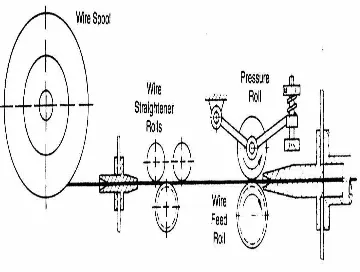
1.2.1 WIRE-FEED UNIT
Figure 1.3 Wire feed unit
to provide continuous control of Armature volts and hence RPM of motor. The wire feed motor spindle has a feed roller fitted and another pressure roll, adjustable spring mounted to lightly grip the wire and push it up the length of the MIG torch.
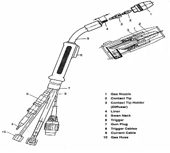
1.2.2MIG TORCH
This provides the method of delivery from the wire feed unit to the point at which welding is required. The MIG torch can be air cooled or water cooled and most modern air cooled torches have a single cable in which the welding wire slides through a Liner. Gas flows around the outside of this Liner and around the tube the Liner sits in is the power braid and trigger wires. The outer insulation provides a flexible cover. Water cooled MIG torches are similar to the above, but gas hose, liner tube, power lead (including water return pipe), water flow pipe and trigger wires are all separate in an outer sleeve. Most industrial MIG equipment uses a standard
European MIG torch connector for easy connection of torch, some low cost smaller units use individual manufacturer’s fittings. The important areas of maintenance are: Liners are in good condition and correct type and size; Contact tips are lightly fitted, of correct size and good condition.
Figure 1.4 MIG Torch
II. SHIELDING GAS
It involves various mixtures of gases available, but the primary purpose of the shielding gas in the MIG process is to protect the molten weld metal and heat affected zone from oxidation and other contamination by the atmosphere. The shielding gas should also have a pronounced effect on the following aspects of the welding operation and the resultant weld.
Argon is also commonly mixed with other gases, oxygen, helium, hydrogen, and nitrogen. The addition of up to 5% oxygen (like the higher concentrations of carbon dioxide mentioned above) can be helpful in welding stainless steel, however, in most applications carbon dioxide is preferred. Increased oxygen makes the shielding gas oxidize the electrode, which can lead to porosity in the deposit if the electrode does not contain sufficient deoxidizers. Excessive oxygen, especially when used in application for which it is not prescribed, can lead to brittleness in the heat affected zone. Argon-helium mixtures are extremely inert, and can be used on nonferrous materials. A helium concentration of 50%–75% raises the required voltage and increases the heat in the arc, due to helium's higher ionization temperature. Hydrogen is sometimes added to argon in small concentrations (up to about 5%) for welding nickel and thick stainless steel workpieces. In higher concentrations (up to 25% hydrogen), it may be used for welding conductive materials such as copper. However, it should not be used on steel, aluminum or magnesium because it can cause porosity and hydrogen embrittlement.
with small amounts of argon and carbon dioxide added. However, because it is less dense than air, helium is less effective at shielding the weld than argon—which is denser than air. It also can lead to arc stability and penetration issues, and increased spatter, due to its much more energetic arc plasma. Helium is also substantially more expensive than other shielding gases. Other specialized and often proprietary gas mixtures claim even greater benefits for specific applications.
The desirable rate of shielding-gas flow depends primarily on weld geometry, speed, current, the type of gas, and the metal transfer mode. Welding flat surfaces requires higher flow than welding grooved materials, since gas disperses more quickly. Faster welding speeds, in general, mean that more gas must be supplied to provide adequate coverage. Additionally, higher current requires greater flow, and generally, more helium is required to provide adequate coverage than if argon is used. Perhaps most importantly, the four primary variations of GMAW have differing shielding gas flow requirements—for the small weld pools of the short circuiting and pulsed spray modes, about 10 L/min (20 ft³/h) is generally suitable, whereas for globular transfer, around 15 L/min (30 ft³/h) is preferred. The spray transfer variation normally requires more shielding-gas flow because of its higher heat input and thus larger weld pool. Typical gas-flow amounts are approximately 20–25 L/min (40–50 ft³/h).
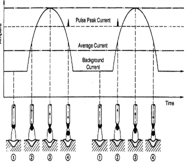
III. PULSED CURRENT TRANSFER
Figure 1.6 Pulsed Current Metal transfer
The Pulsed mode of metal transfer in MIG is used for applications where a good penetration and reduced heat input are required. A pulsed current transfer is a spray type of transfer that occurs at regularly spaced intervals instead of constantly. This mode of metal transfer can only be produced if the power source is able to supply a pulsed current. The level of a welding current supplied by a pulsing type of power source varies between high and low levels. Whereas high level is above the transition current and produces the droplets, low level or background current has only sufficient energy to sustain the arc. In this system of transfer, the droplets have a size equal to the diameter of the wire electrode and theoretically the machine can be set up so that one drop of molten metal can be transferred across the arc during each pulse of high current. There is no metal transfer at low pulse level.
electrode diameters from 0.030” – 1/16” (0.8 – 1.6 mm) solid wire electrodes and metal-cored electrodes from 0.045” – 5/64”(1.1 – 2.0 mm) diameter. It is used for welding a wide range of material types.Argon based shielding gas selection with a maximum of 18% CO2 supports the use of pulsed spray metal transfer with carbon steels.The welding current alternates between a peak current and a lower background current, and this controlled dynamic of the current results in a lower average current than is found with axial spray transfer. The time, which includes the peak current and the background current, is a period, and the period is known as a cycle (Hz). The high current excursion exceeds the globular to spray transition current, and the low current is reduced to a value lower than is seen with short-circuiting transfer. Ideally, during the peak current, the high point of the period, a single droplet of molten metal is detached and transferred across the arc. The descent to the lower current, known as the background current, provides arc stability and is largely responsible for the overall heat input into the weld. The frequency is the number of times the period occurs per second, or cycles per second. The frequency of the period increases in proportion to the wire feed speed. Taken together they produce an average current, which leverages its use in a wide material thickness range.
IV. RESULTS OF ORTHOGONAL ARRAY EXPERIMENTS
bead width (W), reinforcement height (H), and depth of penetration (P) of all the beads are measured. Convexity index of the beads is computed using W and H. The relative contributions of the factors are determined from the analysis of variance (ANOVA) table. Optimization of the parameters is carried out using MINITAB 15.
ANALYSIS OF VARIANCE
The purpose of analysis of variance is to investigate process parameters that significantly affect the desired performance characteristic. This is accomplished by separating the total variability of the response into contributions by each of the process parameters and the error. The total sum of squared deviation SST is decomposed into two sources: the sum of the squared deviations SSd due to each process parameter and the sum of squared error SSe. The percentage contribution by each of the process parameters in the total sum of the squared deviations SST can be used to evaluate the importance of the process parameter change on the performance characteristic. The variance ratio, denoted by F, is the ratio of the mean square due to a factor and the error mean square. A large value of F means that the effect of that factor is large compared to the error variance. Also, the larger the value of F, the more significantly that factor is influencing the performance characteristic (i.e., penetration, convexity).
Analysis of variance (ANOVA) tests the hypothesis that the means of two or more populations are equal. ANOVAs assess the importance of one or more factors by comparing the response variable means at the different factor levels. The null hypothesis states that all population means (factor level means) are equal while the alternative hypothesis states that at least one is different.
To perform an ANOVA, you must have a continuous response variable and at least one categorical factor with two or more levels. ANOVAs require data from approximately normally distributed populations with equal variances between factor levels. However, ANOVA procedures work quite well even if the normality assumption has been violated, unless one or more of the distributions are highly skewed or if the variances are quite different. Transformations of the original dataset may correct these violations.
For example, you design an experiment to assess the durability of four experimental carpet products. You put a sample of each carpet type in ten homes and you measure durability after 60 days. Because you are examining one factor (carpet type) you use a one-way ANOVA.
If the p-value is less than your alpha, then you conclude that at least one durability mean is different. For more detailed information about the differences between specific means, use a multiple comparison method such as Tukey's. The name "analysis of variance" is based on the approach in which the procedure uses variances to determine whether the means are different. The procedure works by Comparing the variance between group means versus the variance within groups as a way of determining whether the groups are all part of one larger population or separate populations with different characteristics.
3 2 1 9 8 7 6 5 3 2
1 1 2 3
3 2 1 9 8 7 6 5 3 2 1 PLATE THICKNESS M e a n o f M e a n s
FREQUENCY WELDING SPEED
WELDING VOLTAGE WELDING CURRENT
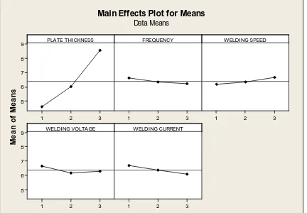
Main Effects Plot for Means
Data Means
Fig. 5.1 Effect of factor levels on depth of penetration
SOURCE DF SEQ SS
ADJ SS
ADJ MS
F P %
CONTRIBUTION
SIGNIFICANCE
PLATE THICKNESS
2 48.7426 48.7426 24.3713 189.18 0.000 92.53 SIGNIFICANT
FREQUENCY 2 0.4585 0.4585 0.2293 1.78 0.237 0.87 - WELDING
SPEED
2 0.7251 0.7251 0.3625 2.81 0.127 1.38 -
WELDING VOLTAGE
2 0.7233 0.7233 0.3616 2.81 0.127 1.37 -
WELDING CURRENT
2 1.1284 1.1284 0.5642 4.38 0.058 2.14 -
RESIDUAL ERROR
7 0.9018 0.9018 0.1288 1.71 -
TOTAL 17 52.6796
Table 5.2 Results of ANOVA for Depth of Penetration
V. EXPERIMENTAL SETUP
1.6 A3xxx ALUMINIUM ALLOY APPLICATION
Typical uses aircraft pump parts, automotive transmission cases, aircraft fittings andcontrol parts, water-cooled cylinder blocks. Other applications where excellent castability and good weldability, pressure tightness, and good resistance to corrosion are required.
1.7A6xxx ALUMINIUM ALLOYSAPPLICATION
6061 is widely used for construction of aircraft structures, such as wings and fuselages, more commonly in homebuilt aircraft than commercial or military aircraft.
2.RAW MATERIAL PREPERATION
VI. CONCLUSION
The mathematical model predicting Depth of Penetration and Convexity Index has been formulated using Multi Regression with reasonable accuracy. Taguchi methods were carried out to optimize pulsed parameters in order to predict Depth of Penetration and Convexity Index.
The following observations were made in optimizing pulsed parameters and in developing mathematical model that correlates pulsed parameters and weld bead geometry parameters such as Depth of Penetration and Convexity Index:-
The bead geometry is mainly influenced by plate thickness and welding speed ratio in pulsed gas metal arc welding.
Finger type penetration is predominant in P-GMAW. At low welding current, the convexity is high in pulsed gas metal arc welding.
The depth of penetration is better at intermediate pulse frequency level, i.e., 101 Hz compared to other pulse frequency levels.
High welding current results in high convexity. This is because at high peak current, the peak duration is less (for the same mean current), which will result in quick cooling of weld pool.
Penetration is more at lower peak current because of high welding speed.
Confirmation tests revealed that beads with low convexity can be obtained by selecting appropriate parameters (A1B3C3D3E3).Confirmation tests revealed that beads with high depth of penetration can be obtained by selecting appropriate parameters (A1B2C3D3E1).
The optimum bead geometry can be obtained by selecting higher welding speed, low frequency on thin base plate. The welding voltage is to be selected suitably depending on thickness of base plate.
The mathematical models developed can predict the depth of penetration and convexity index in conventional P-GMAW with good accuracy.
REFERENCES
1. P.srinivasa Rao, O.P.Gupta, S.S.N.Murty and A.B.Koteswara Rao(2009), Effect of process parameters and mathematical model for the prediction of bead geometry in Pulsed GMA welding, Int J Adv Manuf Technol 45:496-505, DOI: 10.1007/s00170-009-1991-1
2. T. Kannan & J. Yoganandh(2010), Effect of process parameters on clad bead geometry and its shape relationships of stainless steel claddings deposited by GMAW, Int J Adv Manuf Technol (2010) 47:1083–1095, DOI 10.1007/s00170-009-2226-1
3. V.k.goyal, P.K.Ghosh and J.S.Saini(2008), Influence of Pulse Parameters on Characteristics of Bead-on-Plate Weld Deposits of Aluminum and Its Alloy in the Pulsed Gas Metal Arc Welding ProcessThe Minerals, Metals & Material Society and ASM International, DOI: 10.1007/s116661-008-9637-8Farhad Kolahan, Mehdi Heidari(2010), A New Approach for Predicting and Optimizing Weld Bead Geometry in GMAW, International Journal of Mechanical Systems Science and Engineering 2:2 2010
4. P. K. Palani . N. Murugan(2006), Development of mathematical models for prediction of weld bead geometry in cladding by flux cored arc welding, Int J Adv Manuf Technol (2006) 30: 669–676, DOI 10.1007/s00170-005-0101-2
5. J. P. Ganjigatti & D. K. Pratihar & A. RoyChoudhury(2008), Modeling of the MIG welding process using statistical approaches, Int J Adv Manuf Technol (2008) 35:1166–1190 DOI 10.1007/s00170-006-0798-6
6. Kamal Pal & Sandip Bhattacharya & Surjya K. Pal(2009), Prediction of metal deposition from arc sound and weld temperature signatures in pulsed MIG welding, Int J Adv Manuf Technol (2009) 45:1113–1130, DOI 10.1007/s00170-009-2052-5
7. Kamal Pal and Surjya K. Pal(2010), Effect of Pulse Parameters on Weld Quality in Pulsed Gas Metal Arc Welding: A Review, JMEPEG (2011) 20:918–931 ASM International DOI: 10.1007/s11665-010-9717-y
8. S. Kim, A. Basu and E. Siores(1996), Mathematical Models for Control of Weld Bead Penetration in the GMAW Process, Int J Adv Manuf Technol (1996) 12:393-401
9. McGlone JC (1982) Weld bead geometry prediction—a review. Met Constr 14:378–384
10. Pandey S, Parmer RS (1989) Mathematical models for predicting bead geometry and shape relationships for MIG welding of aluminum alloy 5083. Proceedings of the 2nd International Conference on Trends in Welding Technology USA, 14–18 May, pp 37–41
11. Senthil Kumar R.and Parmar RS (1986) Weld bead geometry prediction for pulse MIG welding. Proceedings of an International Conference on Trends in Welding Technology, USA, 18–22 May, pp 647–652
12. Kim IS, Kwon WH, Siores E (1996) An investigation of a mathematical model for predicting weld bead geometry. Can Metall Q 35(4):385– 392. doi:10.1016/S0008-4433(96)00012-2
13. Kim IS, Park CE, Jeong YJ, Son JS (2001) Development of an intelligent system for selection of the process variables in gas metal arc welding processes. Int J Adv Manuf Technol 18:98–102. doi:10.1007/s001700170080
14. Kim IS, Son JS, Kim IG, Kim JY, Kim OS (2003) A study on relationship between process variables and bead penetration for robotic CO2 arc welding. J Mater Process Technol 136:139–145. doi:10.1016/S0924-0136(02)01126-3
15. Kim IS, Son KJ, Yang YS, Yarlagada PKDV (2003) Sensitive analysis for process parameters in GMA welding processes using a factorial design method. Int J Mach Tools Manuf 43:763–769. doi:10.1016/S0890-6955(03)00054-3
16. Ramaswamy S, Gould J, Workman D (2002) Design-ofexperiments study to examine the effect of polarity on stud welding. Weld J 81(2):19– 26s
17. Allen TT, Richardson RW, Tagliabue DP, Maul GP (2002) Statistical process design for robotic GMA welding of sheet metal. Weld J 81(5):69–77s
18. Montogomory DC (2001) Design and analysis of experiments, 5th edn. Wiley, New York 19. Weber DC, Skillings JH (2000) A first course in the design of experiments. CRC, Boca Raton
20. Bradley, G. R. & James, M. N., 2000, “Geometry and Microstructure of Metal Inert Gas and Friction Stir Welded Aluminium Alloy 5383-H321”, M. S. Thesis, University of Plymouth, UK, Vol 67, pp 70.
21. Luijendijk, T., 2000, “Welding of Dissimilar Aluminium Alloys”, Journal of Materials Processing Technology, Vol 103, pp. 29-35.
22. Gómez de Salazar, J. M. & Barrena, M. I., 2003, “Dissimilar Fusion Welding of AA7020/MMC Reinforced with Al2O3 Particles: Microstructure and Mechanical Properties”, Materials Science &Engineering A, Vol 352, pp 162-168.
23. Urena, A., Escalera, M. D. & Gil, L., 2000, “Influence of Interface Reactions on Fracture Mechanisms in TIG Arc-Welded Aluminium Matrix Composites”, Composites Science and Technology, Vol 60, pp 613-622.