Flow Modification over Rotor Blade with
Boundary Layer Control Technique
Navneet Kumar1, Twisha Patel2
P.G. Student, Department of Aerospace Engineering, Indian Institute of Technology, Kanpur, Uttarpradesh, India1 U.G. Student, Department of Aerospace Engineering, University of Petroleum and Energy Studies, Dehradun,
Uttarakhand, India2
ABSTRACT:The performance of transonic aircraft majorly depends on the compressor rotor blade efficiency and engine weight. To increase rotor blade efficiency flow separation over rotor blade must be prevented and controlled. The aim was to modify and control the flow behaviour over compressor rotor blade by using combination of suction and blowing boundary layer control method.
Rotor blade geometry has been modelled in CATIA V5 and then one suction surface and one blowing surface has been created on the blade surface. These geometries have been imported to ANSYS CFX 14.5 for computational simulation and analysis of rotor blade flow with and without boundary layer control technique. Suction slot has been applied at the trailing edge of the suction surface and blowing slot has been applied at 55% of the blowing surface and shear stress transport model has been used for computational analysis.
Two mass flow rates of 1kg/s and 1.5kg/s have been used here for boundary layer control method and boundary layer separation effects have been observed and this could be readily seen as the reattachment of velocity vectors which prevented the flow separation and increment in pressure ratio has been found to be 0.12.
KEYWORDS: Boundary Layer, Blowing, compressor, isentropic efficiency, Rotor blade, Pressure ratio, Suction
I. INTRODUCTION
Efficiency of aircraft gas turbine engines in transonic flow can be increased with the use of compressor having multiple stages and high pressure ratio but this kind of configuration leads to increment in weight and cost also. A lot of researches were done in this field and our aim is achieving high pressure ratio so that efficiency of compressor can be increased. Performance of compressor blade in transonic flow which is partly high subsonic and low supersonic is very important due to occurrence of shock wave which leads to flow separation and this causes different type of losses and this will affect the performance of compressor and therefore performance of engine also reduces. To avoid these losses and to prevent or delay separation different methods like actuating devices, modification in geometry of axial fans etc. are used today and in this paper BL control methods are used to delay or modify flow separation of blade.
flow depends on the blade geometry. 1.1 Rotor Blade Specifications
Table 1 Properties of Rotor Blade
Design Pressure Ratio - 1.61 Mass flow rate - 32 kg/s Rotational speed - 16000 Tip speed - 426 m/s Solidity at the hub - 2.95
Solidity at the tip - 1.33
1.2 Boundary layer and losses
Boundary layer is the layer where flow is retarded due to significant viscosity effect and this layer play key role in deciding performance parameters because flow separation depends on this layer and parameters like pressure, entropy, temperature, viscous layer depends on flow separation. Early flow separation reduces the performance of engines therefore boundary layer needs to be controlled to delay or prevent separation.
In this type of turbo machinery loss mechanism is divided into two groups i.e. Internal and Parasitic loss mechanism. Internal is associated with the main flow through the compressor while parasitic is associated with minor flow loss leaking away from major flow of the compressor. Major losses in transonic flow compressor are as follows:
Shock
Blade loading and leakage
Clearance and profile
Annulus and secondary 1.3 Boundary Layer control methods
BL is the region where mass, momentum and heat transfer are felt and due to these flow is retarded and undergoes various types of losses which reduces performance therefore BL control is necessary to achieve desire performance. BL control refers to the controlling behaviour of fluid flow over rotor blades.
Combination of suction and blowing methods are used simultaneously here as one BL control method. In Suction method a suction surface and suction hole has been created on blade surface and which helps in reenergizing the flow by sucking low energy fluid on the blade surface whereas in Blowing type blowing surface and blowing hole has been created near half of the chord of blade surface through which high energy fluid has been blown over the low energy fluid flow surfaces and this high energy fluid got mixed with low energy fluid and as a result energy of previously fluid has been increased and flow over blade surfaces becomes more smooth and separation has been delayed or prevented. Features of suction and blowing methods are combined in one single method and then observing the effect of this combined method.
1.4 Equation
Isentropic efficiency
In the “equation 1” PR is the pressure ratio and is the specific heat ratio for air which has the standard numerical value of 1.4. & are the total temperatures of outlet and inlet respectively.
II. RELATEDWORK
To increase the performance of transonic aircraft many researches has been made in this field. There are various devices and methods available today to prevent compressor flow instabilities. Some of the methods are casing treatment, tiny grooves or slots made on endwall etc. and these methods have been employed to compressor rotor blade in the late 1970s’. Many methods like adding plasma actuating devices on the trailing edge of blade, Boundary layer control by suction etc. have been developed to delay or prevent separation.
Features of suction and blowing method has been used separately on the rotor blade separately but not at the same time. Before using this control surfaces in our geometry we have done a lot of literature survey to get appropriate coordinates of rotor blade surface and we got these points from the researches made in 90’s.
Suction and blowing has been used in many other researches to prevent flow separation and these methods has delayed flow separation and reduces the boundary layer effects especially on airfoils. Due to the occurrence of shocks in transonic flow, Performance of compressor rotor has been decreased therefore researches has been made in this field so that performance of the rotor could be increased by some means.
In the previous researches suction and blowing both methods has been used but in this research we want to use features of both the methods at the same time and by this mean we want to avoid or delay flow separation so that flow remain attached to the blade and velocity vectors should be smooth so that we got high pressure ratio per stage. When suction method has been used in the previous researches then increment in pressure ratio was not much effective and when blowing has been used then increment in pressure ratio was more than suction therefore we got the idea of using both the methods at the same time to reduce compressor instabilities and to increase performance of transonic axial compressor.
III. METHODOLOGY
3.1 Modelling
Modelling of rotor blades has been done in CATIA V5 (a software used for modelling and designing any object).Modelling of compressor rotor blade is not an easy job due to complexity of curve i.e. it is twisted from hub to tip, unless we do not have proper coordinates of points, blade modelling is not possible and these coordinates of point can be obtained from literature survey of researches made in this field. First modelling of single surface has been done by joining coordinates of four points and then formation of all surfaces of blade has been done by joining coordinates of all the points then geometric model of blade is ready and after this casing hubs and outer walls of blades has been modelled and this depends on the tip clearance chosen.
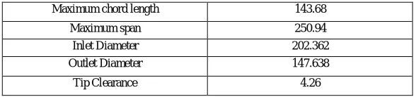
Table 2 Important parameters of Model
Maximum chord length 143.68
Maximum span 250.94
Inlet Diameter 202.362
Outlet Diameter 147.638
Fig.1 Geometric model of rotor blades
There were thirty six blade in single rotor stage of compressor which has been shown in Fig.1 and number of elements corresponding to each blade was very high due to which this would take too much of computational time and cost.
Fig.2 Single blade model with outer walls and casing
To overcome this problem and to reduce our computational cost and time our model has been restricted to single blade geometric model which has been shown below in Fig.2 and results and analysis has been done for this model only.
3.2 Grid and mesh parameters
3.2.1 Grid generation and mesh parameters without boundary layer control
Grid creation was very important phase in CFD simulations and if grid was of bad quality then our results were not good. In this paper for shell meshing Quad dominant mesh type has been used and patch dependent method has been used for obtaining this and for volume mesh tetra or mixed type mesh has been used and robust method helps in achieving this.
been created on blade then the outer wall and casing.
To consider boundary layer effects on the flow height was kept as constant and number of prism layers has been calculated using Y+ calculators.
Figure 3 Parameters setup for part mesh
First global mesh parameters has been defined and after this part mesh parameters has been defined which has been shown in the above Fig.3 In the part mesh setup different element sizes have been defined to create coarsen mesh on the edge of the blade. When all the parameters have been defined then create prism layer and then apply compute for generating mesh grids. Grid generation of single blade has been shown in Fig.4 and Grid of outer walls and casing has been shown in Fig.5.
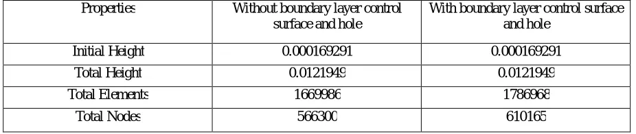
Table 3 Mesh parameters of Grids of model with and without blowing boundary layer control surface
Properties Without boundary layer control surface and hole
With boundary layer control surface and hole
Initial Height 0.000169291 0.000169291 Total Height 0.0121949 0.0121949 Total Elements 1669986 1786968
Figure 4 Grid generation of blade on single blade model
Grid or mesh generation on the blade surfaces has been shown in Fig.4 and two different views has been shown in this Fig. at the surface of blade grids were very fine because this was the domain where flow behaviours were very important.
Figure 5 Grid generation of blade on outer walls and casing
Grids formation on the geometry other than blade surface has been shown in the Fig.5 and grids of these outer walls and casings were not very fine because flow behaviour around these surfaces were out of our interest.
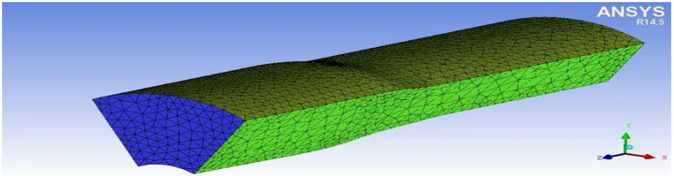
3.2.2Grid generation with boundary layer control surface
Fig.6 Grid generation of blade model with control surfaces
Grid generation of blade surfaces having suction and blowing control surfaces has been shown in Fig.6 and on the suction and blowing surface grids were very fine because we have more interest on the flow behaviour on these surfaces.
3.3 Boundary conditions for computational simulation
Computational Fluid Dynamics has been used to solve the model associated with the fluid flow by applying numerical methods. There were many CFD software’s like ANSYS- (GAMBIT, FLUENT and CFX etc.), OPEN FOAM, Gerrish Flow solver etc. available today for computational simulation and analysis. Among all these software’s ANSYS CFX was high performance CFD tool which delivers accurate and reliable solutions therefore ANSYS CFX has been used in our study. This software has three tools to do computational simulation and analysis and they were CFX-pre-processor, CFX solver manager and CFX-post processor.
3.3.1CFX pre-processor
This part of CFD tool worked as pre-processor for the simulation software. Grid file produced in ICEM should be imported to the CFX-pre by generating CFX input file of that model. After this open this file from CFX-pre and then domain should be created in pre-processing software and this problem is defined in turbo mode. Turbo mode has been used to provide some pre-specified conditions.
3.3.1.1 CFX Pre setup for model without boundary layer control surfaces The settings for CFX- Pre used are based on the units of the mesh imported. The parameters for the mesh units in mm are:-
Basic Settings
Machine Type : Axial Compressor
Rotation Axis : z
Component type
Type : Rotating
Value -16043 [RPM]
Tip clearance at shroud : yes
Fluid :-- Air Ideal Gas
Analysis Type : -- Steady State
Model data :
Reference Pressure :- 0 (Zero) Pa
Heat Transfer :- Total Energy
Turbulence :- Shear stress Transport
Wall Functions :- Automatic and compressible high speed heat transfer model
Inflow Boundary condition:
Mass and Momentum :- Static Frame Total Pressure
Relative Pressure ( P- Total) :- 101325 Pa
Flow direction :- Normal to the boundary
Static Frame Total temperature :- 288.2 K
Outlet Boundary condition:
Mass and Momentum :- Static Pressure and mention pressure as 114500 Pa
Solver Parameter :
Advection Scheme :- High Resolution
Time Scale Control :- Auto Timescale
Length Scale :- Conservative
Maximum Timescale :- 0.000001
Convergence Residual Criteria:- MAX Type and Target as 0.00001 The parameters for the mesh units in cm are:-
Basic Settings
Machine Type : Axial Compressor
Rotation Axis : z
Component type
Type : Rotating
Value -3600 [RPM]
Tip clearance at shroud : yes
Fluid :-- Air Ideal Gas
Analysis Type : -- Steady State
Model data :
Reference Pressure :- 0 (Zero) Pa
Heat Transfer :- Total Energy
Turbulence :- Shear stress Transport
Wall Functions :- Automatic and compressible high speed heat transfer model
Inflow/Outflow boundary templates: P-total inlet P-static outlet
Inflow Boundary condition:
Mass and Momentum :- Static Frame Total Pressure
Relative Pressure ( P- Total) :- 101325 Pa
Flow direction :- Normal to the boundary
Static Frame Total temperature :- 288.2 K
Outlet Boundary condition:
Mass and Momentum :- Static Pressure and mention pressure as 114500 Pa
Solver Parameter :
Advection Scheme :- High Resolution
Time Scale Control :- Auto Timescale
Length Scale :- Conservative
Maximum Timescale :- 0.000001
Convergence Residual Criteria:- MAX Type and Target as 0.00001 3.3.1.2 CFX Pre setup for model with boundary layer control surfaces
The parameters for the problem applied are:-
Basic Settings
Rotation Axis : z
Component type
Type : Rotating
Value -16043 [RPM]
Tip clearance at shroud : yes
Fluid :-- Air Ideal Gas
Analysis Type : -- Steady State
Model data :
Reference Pressure :- 0 (Zero) Pa
Heat Transfer :- Total Energy
Turbulence :- Shear stress Transport
Wall Functions :- Automatic and compressible high speed heat transfer model
Inflow/Outflow boundary templates: P-total inlet P-static outlet
Inflow Boundary condition:
Mass and Momentum :- Static Frame Total Pressure
Relative Pressure ( P- Total) :- 101325 Pa
Flow direction :- Normal to the boundary
Static Frame Total temperature :- 288.2 K
Outlet Boundary condition:
Mass and Momentum :- Static Pressure and mention pressure as 114500 Pa
Suction:
Mass and Momentum :- Outlet and mass flow rate of 1 Kg/s
Blowing:
Mass and Momentum :- Inlet and mass flow rate of 1.5 Kg/s
Solver Parameter :
Advection Scheme :- High Resolution
Time Scale Control :- Auto Timescale
Length Scale :- Conservative
Maximum Timescale :- 0.000001
Convergence Residual Criteria:- MAX Type and Target as 0.00001
3.3.2 CFX solver manager
3.3.3 CFX post-processor
The result or output file of CFX solver manager worked as input file for this tool and first that output file has been loaded in to this tool. When the results were initialized thermodynamic properties can also be extracted from optimization process therefore expression of isentropic efficiency and pressure ratio has been also created in expression tab of CFD-Post.
IV. RESULTSANDDISCUSSION
There were two defined models for analysis and this analysis has been done in CFX post-processor. First model without any boundary layer control surfaces has been analysed and then model with combination of suction and blowing boundary layer control surfaces. Three dimensional simulations have been done by using simulation software ANSYS CFX. In post processing results have been analysed in the form of velocity vectors. Velocity vectors has been checked not at various section of span but also at two models with changed length units and rpm.
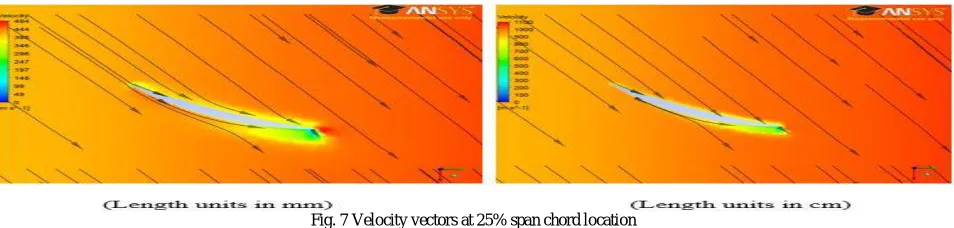
Fig. 7 Velocity vectors at 25% span chord location
Flow behaviour in the form of velocity vectors at quarter chord location has been shown in the above fig. and this has been done for two different scale and vortex of strong strength could be seen here as the flow has been separated and boundary layer effects were dominant here.
Fig.8 Velocity vectors at 50% span chord location
Fig.9 Velocity vectors at 80% span chord location
Flow behaviour at 80% chord location has been shown in Fig.9 and two different length scale has been used and it has been found that results were similar for both length scale and in this case very tiny strength vortex has been observed and Boundary layer effects were negligible.
Fig.7, 8 and 9 represented velocity vectors at 25%, 50% and 80% span location respectively. When results have been analysed then it has been observed that boundary layer effects were dominant near quarter chord of span which could be seen in the above Fig.7 At quarter chord location flow separation has been occurred i.e color changes from orange to green and some strong vortex has been also formed at this location. At 50% and 80% span location flow separation has been also occurred but boundary layer effects were not as dominant as in near quarter chord location and very small vortex of tiny strength has been formed also and this could be seen in Fig.8 and Fig.9.
Flow analysis has been done for models with two different length scale and it was found that results were similar for both models. Results have been shown in the form of velocity vectors, at quarter chord location velocity vectors were not smooth as the boundary layer effects were dominant here and due to this flow separation has been occurred and this could be seen in the above three Fig. and at other two span location velocity vectors has been found to be smoother than at quarter chord location.
From the results obtained it was clear that we need to develop some steps through which flow separation could be delayed or prevented and for this combination of suction and blowing methods has been used in this study.
Results for the model with the combination of suction surface and blowing surface has been analysed and Velocity vectors for three span location of blade i.e at 25%, 50% and 80% span location which has been shown in Fig.10,11 and 12 respectively. In the suction method suction surface and suction hole has been created on the blade surface and results has been obtained for mass flow rate 1kg/s and in blowing method blowing surface and blowing hole has been created on the blade surface and results has been obtained for two mass flow rate 1.5kg/s. Suction surface has been used to suck the low energy fluid and blowing surface has been used to blow high energy fluid to the flow and here feature of both the methods has been combined and used as a single method.
Fig.10 velocity vectors for model with control surfaces at 25% span chord location
Fig.11 velocity vectors for model with control surfaces at 50% span chord location
Flow behaviour in the form of velocity vectors at half chord location with the introduction of suction and blowing control surfaces has been shown in Fig.11 and velocity vectors were smooth and very ting vortex could be seen.
Fig.12 velocity vectors for model with control surfaces at 80% span chord location
Flow behaviour in the form of velocity vectors at 80% chord location with the introduction of blowing and suction control surfaces has been shown in the Fig.12 and in this no vortex has been seen and flow separation has been prevented.
High energy fluid has been blown to the flow through blowing hole and suction surface used to suck the low energy fluid through suction holes and in this study both the processes has been worked simultaneously and fluid has been reenergized and there were no low energy fluid due to which flow separation occurred by this way flow separation has been prevented. From the above figure it could be shown that by the use of boundary layer control method velocity vectors found to be smoother and no strong vortex has been seen.
V. CONCLUSIONS
Results has been obtained for the both model i.e model with and without boundary layer control surfaces and it has been obtained that flow separation has been delayed or prevented with the introduction of combination of suction and blowing surface in the blade geometry. When there was no boundary layer control surface then flow separation occurred and boundary layer effects were dominant near quarter chord location due to this some strong vortices has been formed but with the introduction of blowing and suction control surface in the blade geometry flow separation has been prevented and vortex of very tiny strength has been observed. As a result pressure ratio has been observed as 1.724 and increment in pressure ratio has been found to be 0.11.
ACKNOWLEDGEMENTS
REFERENCES
[1] Kumar N., “Flow modification over rotor blade with suction boundary layer control technique”, International Journal of Engineering Research and Application, Vol.6, no.6, pp 1-5, 2016.
[2] Kumar N., “Modification of rotor blade flow with blowing boundary layer control technique”, International Journal of Multidisciplinary Educational Research, vol.5, no.7, pp209-228, 2016.
[3] Y. Ito, T. Watanabe and T. Himeno, “Effect of Endwall Countering on Flow Instability of Transonic Compressor”, International Journal of Gas Turbine, Propulsion and Power system, Vol.2, no.1, 2008.
[4] N. Ananthkrishnan, U. G. Vaidya and V. W. Walimbe, “Global stability and control analysis of axial compressor stall and surge phenomena using bifurcation method”, Institution of mechanical Engineers J Power and Energy, vol.217, no.1, 2001.
[5] Abate, Giada,“Aerodynamic optimization of transonic axial compressor rotor”, Journal of Propulsion and Power, vol.54, no.4, pp.41-55, 2003.
[6] Benini and Ernesto,“Three dimensional multi objective design aerodynamic optimization of transonic compressor rotor”,International Journal of Gas Turbine, Propulsion and Power System, vol.54, no.5, 2004.
[7] Brian Joseph Schuler, “Experimental Investigation of an aspirated fan stage, doctoral diss.”, Massachusetts Institute of Technology, Cambridge, MA, 2001.