Hydraulic Cylinder Piston-Rod Joint
Tightening Torque Analysis
M. Antony Maria Thomas Benny1, U.S. Chavan2
P.G. Student, Department of Mechanical Engineering, Vishwakarma Institute of Technology, Pune, India1
Professor, Department of Mechanical Engineering, Vishwakarma Institute of Technology, Pune, India2
ABSTRACT: Hydraulic cylinders are actuators that generates linear translatory motion. Force required for actuation depends on implement requirements and heavier applications were output forces are higher, the internal components of cylinder needs to withstand this higher loads and hence design of hydraulic cylinder internal components gains importance. The cylinder rod and piston inside cylinder are connected jointly either by bolt or nut. Hence it is important to analyse the tightening torque required to keep these joints with no load separation condition.
In this paper the tightening torque required for the joints which experiences higher tensile or compressive loads during operations are concentrated. There are instances during operation the cylinder bottoms-up completely putting high tensile load on rod and piston-rod joint which leads to separation of the piston and rod joints.
In this analysis, a theoretical calculate approach is used to analyse two different type of joints in order to find out maximum required pretension load, tensile stress and respective tightening torque for no separation of joints. Later static structural analysis using Ansys was performed on the two synthesized cylinder concepts to investigate which type of joints produces lesser tensile stresses and are best suitable joint for implements with high tensile load applications
KEYWORDS: Hydraulic cylinder joint, piston-rod joint, bolt preload analysis, tightening torque.
I. INTRODUCTION
A hydraulic cylinder is a complicated mechanical system that are used to provide linear force action and motion. Hydraulic cylinders are powered from externally pressurized hydraulic fluid. They are commonly used in equipment’s and machinery, such as construction equipment like excavators, dozers and material handling equipment’s like carry cranes, telescopic trucks etc.[1-2, 6]
In the majority of applications, where bolts and nuts are used, it is the clamping force provided by torqueing of the bolt/nut plays major role which is crucial factor in determining the structural integrity of the joint [7]. The wrong tightening is one of the most frequent causes of ductile rupture and a frequent cause of fatigue failure [9]. During hydraulic cylinder operations, the tensile or compressive loads that is generated from hydraulic force and implement mechanism acts on the cylinder rod in its axial direction Proper pretension torque values are needed to ensure that the cylinder rod and position joint doesn’t fail during implement operations [9]
II. LITERATURE REVIEW
Several studies have been carried out on bolt and nut tightening torque for different applications based on loads, pretensioning loads under static loading conditions and fatigue loading cycles.
Saman Fernando [3] analysed two mechanisms of vibration loosening bolts and identified critical parameters in preventing loosening of bolt joints. Finally, based on results it was found at least, preload of 65 percent of fastener proof load should prevent loosening under vibration at all vibration environments. John D. Reiff [4] developed procedures for calculating the coefficient of friction of bolt/nut assemblies and for calculating torque specifications which includes the cases where the fasteners have prevailing torque. The new equations developed basically resulted in 15 percent enhancement in the accurateness of torque specification calculations. Jean-Michel Monville [7] investigated that incorrect tightening of bolt joint is one of most common reasons of ductile breakage and also reason for most of frequent cause of fatigue failures. Paper focuses on ‘hydraulic tensioner’ to show how tightening load can be found based on applied pretension load and to suggest a new way for optimization of bolt torqueing procedures. Henri Walaszek [8] studied that ultrasonic method of bolt tightening gives information of stress generated in bolts due to preload. The pre-load provides right measuring of tension generated on bolt joint, independent of manufacturing tolerances. It uses ‘bi-wave method’ using electromagnetically coupled transducers (EMAT) and data of applied stress on bolts with 5% of uncertainty. W. Eccles [9] presented a new approach to check tightness of bolted connection. This shows a new method to find the torque required to rotate and tighten the joint and then instantaneously doing in opposite direction which allows load available on bolted connection to be ascertained correctly. Paul Copeland [10] investigated on ‘Dynamic Tightening of a Bolted Joint’, a novel bolt joint model was established which allows ‘dynamic tightening’ of bolt into threaded holes by physical model behaving non-linearly with helical threaded pattern. Evaluation of clamping load with the original joint exhibited 0.15 percentage variance with the original and FEA bolts. Average plastic deformation on joint bearing surface correlated with original joint.
Closer review
From the literature review it is understood that many works were carried out on bolt and nut torqueing generally for applications. But there are no much work carried out specifically on analysing tightening torque effects on different types of hydraulic cylinder rod-piston joint based on maximum tensile load applications. In this paper, for such high tensile load applications torqueing the joint with bolt or nut which will produce lesser tensile stresses are analysed.
Objective
The main objective of this paper is to analysis the induced tensile stress effect of tightening torque on,
1. Twoconcepts that is whether piston rod connected using bolt or nut will induce maximum tensile stress on the joint after tightening the joint for required joint pretension load based on implement mechanism.
2. Analysis of bolt/nut pretension load and tightening torque for both concepts. 3. FEA analysis of the concepts for tensile loads and pre tension loads.
4. Comparison of theoretical and FEA results to understand which of the two concepts are best suitable for high tensile load application for hydraulic cylinders.
III.LOAD ANALYSIS AND TIGHTENING TORQUE CALCULATION
a) Load Analysis on Piston-rod joint
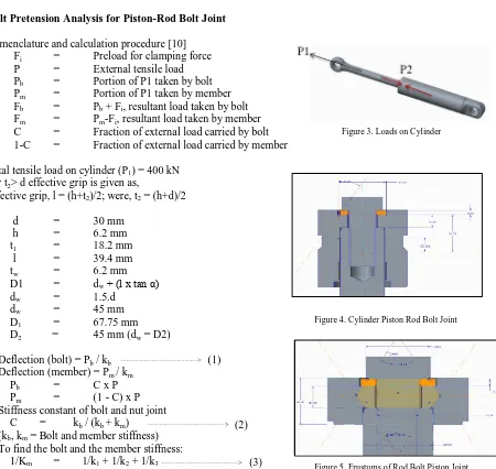
The two major load cases are, 1. Vertical Machine Load and 2. Hydraulic Cylinder Force
From load analysis the total maximum tensile load (P1) from vertical machine load and hydraulic cylinder force
Now, the bolt/nut pretension (P2) required for no separation of piston-rod joint as to be analysed and calculated for
concept-1 and concept-2 types of joints as shown below.
b) Bolt Pretension Analysis for Piston-Rod Bolt Joint
Nomenclature and calculation procedure [10]
Fi = Preload for clamping force
P = External tensile load
Pb = Portion of P1 taken by bolt
Pm = Portion of P1 taken by member
Fb = Pb + Fi, resultant load taken by bolt
Fm = Pm-Fi, resultant load taken by member
C = Fraction of external load carried by bolt 1-C = Fraction of external load carried by member
Total tensile load on cylinder (P1) = 400 kN
For t2> d effective grip is given as,
Effective grip, l = (h+t2)/2; were, t2 = (h+d)/2
d = 30 mm
h = 6.2 mm
t1 = 18.2 mm
l = 39.4 mm
tw = 6.2 mm
D1 = dw+ (l x tan α)
dw = 1.5.d
dw = 45 mm
D1 = 67.75 mm
D2 = 45 mm (dw = D2)
Deflection (bolt) = Pb / kb
Deflection (member) = Pm / km
Pb = C x P
Pm = (1 - C) x P
Stiffness constant of bolt and nut joint C = kb / (kb + km)
(kb, km = Bolt and member stiffness)
To find the bolt and the member stiffness:
1/Km = 1/k1 + 1/k2 + 1/k3 (3)
(2) (1)
Figure 1. Concept -1 Piston-Rod Bolt Joint Figure 2. Concept -2 Piston-Rod Nut Joint
Figure 3. Loads on Cylinder
h = t1 + tw = 24.4 mm
l = (h + d)/2 = 39.4 mm D2 = 1.5d
Stiffness, k = (0.577* π*E*d) .
Ln((1.15t+D-d)(D+d)) / ((1.15t+D+d)(D-d))
Let the joint consists of three frusta's and respective stiffness are k1, k2 and k3 as shown in figure 5,
To find K1: (Upper frustum)
t = l/2 = 0.0197 m; D = D2 = 0.045 m; d = 0.03 m; Young's modulus (E) = 207000 N/m2
Substituting in equation (4),
Stiffness of Joint, k1 (N/m) = 17109.12708
To find K2: (Middle frustum)
t = h - l/2 = 0.0047 m; D = D2 + 2 (l - h) = 0.062 m; d = 0.03 m
Substituting in equation (4),
Stiffness of Joint, k2 (N/m) = 114746.1897
To find K3: (Lower Frustum)
D = 0.045 m; T = l - h = 15 = 0.015 m; d = 0.03 m Substituting in equation (4),
Stiffness of Joint, k3 (N/m) = 20106.571
Substituting k1, k2, k3 in equation (3),
Member Stiffness (km) = 8554.45
Bolt Stiffness (kb) = (At x E) / l
Tensile stress area (At) = 561 mm2
Bolt Stiffness (kb) = 2947.39
Substituting km and kb in equation (2),
Fraction of external load carried by bolt, C = 0.26 Fraction of external load carried by member, 1 - C = 0.74 Bolt Pretension (Fi, max)
At, Sp values for M30 x 3.5, 10.9 grade bolt are,
Fi (max) = 0.75 x Fp
Fp= At x Sp (At = 530 mm2; Sp = 830 Mpa)
Where Fp is proof load and Sp is proof strength
Fi (max) = 349222.5 N
Load factor, n = [(Sp x At) - Fi] / (C x P) = 1.12
Factor that prevents bolt stress becoming equal to proof strength no = Fi / [P x (1 - C)] = 1.2
Minimum preload for no separation of the joint (Fi) happens when load factor (no) = 1
Fi = P x (1 – C) x no
Minimum bolt preload for no separation of the joint (Fi) = P x (1 - C)
Bolt Preload (P2) = 296000 N = 300 kN (approx.)
Concept-1
(6) (5)
(4)
Stress at Fi = 300 kN
σb = [ (C x P2) /At ] + Fi / At
= 569.01 Mpa
Stress at Fi, max. = 349 kN
σb, max = [ (C x P2) /At ] + Fi / At
= 652.11 Mpa (Proof Stress, Sp = 830 Mpa)
Concept-2
Stress at Fi = 300 kN
σb = [ (C x P2) /At ] + Fi / At
= 720.31 Mpa
Stress at Fi, max. = 349 kN
σb, max = [ (C x P2) /At ] + Fi / At
= 825.31 Mpa (Proof Stress, Sp = 830 Mpa)
Tightening torque of bolt/nut type joints required for 300 kN pretension load (clamping force and tightening torque assumed to be same between bolt and nut type of joints)
T = k x d x Fi
(Assumed k = 0.2, for dry fastener)
T (min) = 1800 N-m (at Fi = 300 kN)
T (max) = 2095.5 N-m (at Fi = 349.2 kN)
IV.FINITE ELEMENT ANALYSIS
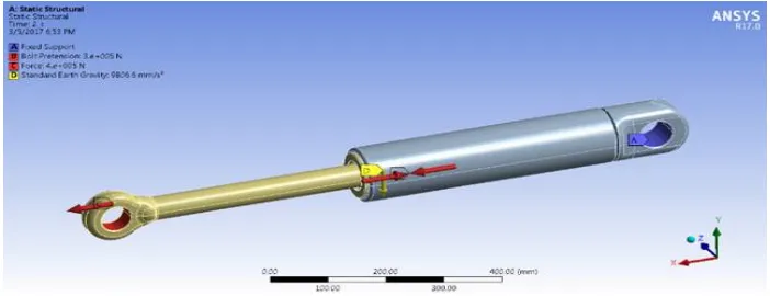
FEA analysis was carried out for the hydraulic cylinder piston-rod concept1 and concept2 type of joints under following loading condition
1. Maximum total tensile Load on cylinder rod of 400 kN; 2. Bolt/nut pretension load of 300 kN for no separation of concet1 and 2 type of joints.
FEA Modelling and Boundary conditions 1. Meshing element type is 4 node quad shell 181.
2. For bolt/nut mesh size 1mm; for rod, piston mesh size 3mm; Barrel, cylinder cup mesh size is 8 mm. 5. Load behaviour is taken as rigid which resembles the practical case.
3. Cylinder barrel end was considered are fixed.
4. Contacts between barrel & cup, bolt/nut thread and cylinder rod threads were considered as bonded. 5. All other contacts were considered as frictional with co-efficient of friction as 0.2
(8)
(7)
Figure 7. Frustum of Rod Nut Piston Joint
Concept-1
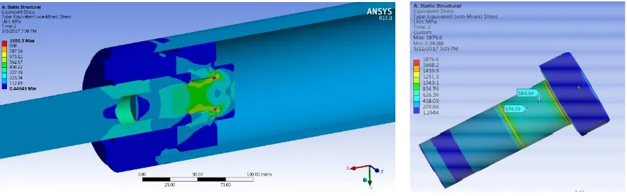
Figure 1, shows the cylinder rod and piston is connected using M30x3.5x70 bolt of Grade 10.9. Bolt pretension was given in the shank region of bolt. Figure 10 (bolt, rod full section, rod cross section) shows equivalent stress distribution of concept1 under 400 kN tensile load and 300 kN pretension load. Maximum variation between calculated & FEA values are 4% approximately as shown in equivalent stress plots figure 9.
Concept-2
Figure 2, shows concept 2 geometry were the cylinder rod and piston is connected using M30x3.5x26 nut of class 10. Bolt pretension was given in the shank region of cylinder rod. Figure 11 (Nut, rod full section, rod cross section) shows equivalent stress distribution of concept1 under 400 kN tensile load and 300 kN pretension load. Maximum variation between calculated & FEA values are 3% approximately as shown in equivalent stress plots figure 10.
V. CONCLUSION
Based on the implement mechanism analyse the total tensile load on cylinder rod including vertical machine weight and hydraulic cylinder force was 400 kN (with factor of safety of 2). From concept-1 & concept-2 geometry analysis
Figure 9. Concept -1 Equivalent Stress Distribution
Figure 11. Concept -2 Equivalent Stress Distribution
Figure 10. Bolt - Equivalent Stress Distribution
the joint pretension load required based on total tensile load was calculated to be 300 kN and tightening torque of 1900 Nm.
In concept-1 piston-rod bolt joint, for bolt, the maximum tensile stress variation between calculated (569.31 Mpa) & FEA analysis (584.24 Mpa) were around 2.56 %
In case of concept-2 piston-rod nut joint, maximum tensile stress variation on nut between calculated (733.21 Mpa) & FEA analysis (743.09 Mpa) were around 1.33 %
Also it is observed that the pretension in concept -1 joint happens on the shank of 10.9 grade M30 bolt with 900 Mpa yield strength were as in case of concept-2, the pretension happens on the cylinder rod shank of EN 19 material with 690 Mpa yield strength.
To conclude, the tensile stresses generated by tightening torque of 1900 Nm and 300 kN pretension load was lesser in concept-1 that is hydraulic cylinder piston rod connected using bolt compared to that of concept -2 that is hydraulic cylinder piston rod connected using nut and threaded plug. Hence concept-1 type joints are suitable for cylinders with high tensile load applications.
REFERENCES
[1] Sh. Molaei, R. Alizadeh, M. Attarian, Y. Jaferian, “A failure analysis study on the fractured connecting bolts of a filter press”, Published by - Elsevier Journal, volume 4, October 2015, pp 26-38.
[2] G. Nicoletto and T. Marin, “Fatigue Optimization of a Heavy-duty Hydraulic Cylinder” Published by - Elsevier Journal, volume 18, issue 3, April 2011 2015, pp 1030-1036.
[3] Dr Saman Fernando, “Mechanisms and prevention of vibration loosening in bolted joints”, Published by – Australian Journal of Mechanical Engineering, September 2015, vol. no. 2, issue 2.
[4] John D. Reiff, “A Procedure for Calculation of Torque Specifications for Bolted Joints with Prevailing Torque”, Published by - Journal of ASTM International, March 2005, vol. 2, issue no. 3.
[5] S.M.O. Tavares, N. Viriato, M. Vaz, P.M.S.T. de Castro, “A failure analysis of the rod of a hydraulic cylinder”, Published by - Elsevier Journal, volume 1, February 2016, pp 173-180.
[6] Jean-Michel Monville , “Optimal tightening process of bolted joints”, Published by International Journal for Simulation and Multidisciplinary Design Optimization (IJSMDO), volume 7, article no. A4, September 2016.
[7] Henri Walaszek, Patrick Bouteille, “Application of ultrasonic measurements to stress assessment on already tightened bolts”, Scientific.net, Tans Tech Publications, volume 524-525, September 2006, pp 459-64.
[8] W. Eccles, “A new approach to the checking of the tightness of bolted connections”, Published by - Fastener plus Fixing Technology Magazine, Issue 15, October - December 2014.