~~-~~----
This manual is published by the Univac Division of Sperry Rand Corporation in loose leaf format. This format provides a rapid and complete means of keeping recipients apprised of UNIVAC
®
Systems developments. The infor-mation presented herein may not reflect the current status of the programming effort. For the current status of the programming, contact your local Univac Representati ve.The Univac Division will issue updating packages, utilizing primarily a page-for-page or unit replacement technique. Such issuance will provide notification of software changes and refinements. The Univac Division re-serves the right to make such additions, corrections, and/or deletions as, in the judgment of the Univac Division, are required by the development of its Systems.
UNIVAC is a registered trademark of Sperry Rand Corporation.
·
UNIVAC 9200/9300 Contents1
UP-76119200/9300 TO 9200/9300 COMMUNICATIONS SECTION: PAGE:
/ '
\.../
CONTENTS
CONTENTS 1 to 2
1. INTRODUCTION 1-1 to 1-2
1.1. SCOPE 1-1
1.2. GENERAL DESCRIPTION 1-1
2. PROGRAM REQUIREMENTS 2-1 to 2-10
2.1. GENERAL 2-1
2.2. RESPONSE TABLE 2-1
2.2.1. Use Key 2-3
2.2.2. Table Identification 2-3
2.2.3. Request Key 2-3
2.2.4. Wraparound Indicator 2-3
2.2.5. Deactivate Key 2-4
2.2.6. Input Interrupt Entry 2-4
2.2.7. Output Interrupt Entry 2-4
2.2.8. Clock Interrupt Entry 2-5
"--"
2.2.9. Commun i cations Buffer A rea Address 2-52.2.10. Receiving Channel Number 2-5
2.2.11.
Logical Unit Number (Device Address) 2-52.2.12. Transmitting Channel Number 2-5
2.2.13. Error Indi cator 2-5
2.2.14. Clock Counter 2-5
2.2.1 S. Input BCW Address 2-6
2.2.16. Output BCW Address 2-6
2.2.17. Status 2-6
2.2.18. Toggle 2-6
2.2.19. Current Packet Address 2-6
2.2.20. Sentinel Key 2-6
2.3. REQUEST PACKETS 2-6
2.3.1. Packet Identification 2-6
2.3.2. Error Count 2-6
2.3.3. Availability Field 2-8
2.3.4. Indicator Code Routine Address 2-8
2.3.5. Work Area Address 2-8
2.3.6. Function Field 2-8
2.3.7. Error Code 2-9
2.3.8. Interlock Field 2-9
2.3.9. Message Size 2-9
2.4. LIN KIN G 2-9
""- -,
UP-7611 UNIVAC 9200/9300 Contents
2'
9200/9300
TO9200/9300
COMMUNICATIONSSECTION PAGE:
3. PROGRAM PROCEDURES 3-1 to 3-2
~
3.l. SCOPE 3-1
3.2. OPEN 3-1
3.3. SEND AND RECEIVE 3-1
3.4. CLOSE 3-2
4. PROGRAMMING CONSIDERATIONS 4-1 to 4-2
4.l. SCOPE 4-1
4.2. PROGRAM COORDINATION 4-1
4.3. RESPONSE TABLE AVAILABILITY 4-1
4.3.1. Master Response Table 4-1
4.3.2. Slave Response Table 4-1
4.3.3. Request Packet 4-2
5. OPERATIONAL CONSIDERATIONS 5-1 to 5-5
5.1. SCOPE 5-1
5.2. DATA TRANSFERS 5-1
5.2.1. Control Blocks 5-1
5.2.2. Data Block 5-2
5.3. CODE GENERATION 5-3
'-.J
5.4. INTERRUPT PROCESSING 5-4
5.5. OPERATION OF COMMUNICATIONS MACRO ROUTINES 5-5
5.5.1. C9MR Macro Routines 5-5
5.5.2. C9SR Macro Routines 5-5
FIGURES
2-1. Master Response Table Format 2-2
2-2. Slave Response Table Format 2-2
2-3. Master Request Packet Format 2-7
2-4. Slave Request Packet Format 2-7
5-1. Transfer of Control for an Interrupt 5-4
UP-7611 UNIVAC 9200/9300
1
9200/9300 TO 9200/9300 COMMUNICATIONS SECTION:PAGE:
1. INTRODUCTION
1.1. SCOPE
This manual describes the Communications routines required to implement the inter-changes of data between two or more UNIVAC 9200/9300 computers. Use of this manual assumes a knowledge of the "UNIVAC 9300 System Operating System Pro-grammers Reference," UP-7531 (current version), "UNIVAC 9200/9300 Systems
Central Processor and Peripherals Programmers Reference," UP-7546 (current version), and "UNIVAC 9200/9300 Systems Card Assembler Programmers Reference," UP-4092 (current version), and "UNIVAC 9200/9300 Systems Programming Utility Programmers Reference," UP-4120 (current version).
1.2. GENERAL DESCRIPTION
Communication between two or more UNIVAC 9200/9300 computers is made possible with Communications routines used in conjunction with the UN IV AC Data Communica-tions System (DCS) equipment.
The 9200/9300 to 9200/9300 Commun~cations routines provide an interface between problem programs and the Operating System. There are two routines: a master routine (C9MR) which is linked with a problem program, and a slave routine (C9SR) linked with another closely integrated problem program. Both routines are capable of sending and receiving messages; however, only the master routine may initiate the transmission of data. There may be more than one slave program, each incorporating a slave routine, operating with a single master program.
The master and slave routines are supplied in relocatable form in the UNIVAC 9200/9300 Systems software library.
The connecting link between the master problem program and the master routine is the Response Table. This table must be defined by the programmer and contains a unique set of characteristics which describe a file. The master routine uses the table to maintain the current status of an interchange. There must be a Response Table for each slave program with which the master program communicates.
UP-7611 UNIVAC 9200/9300
9200/9300
TO9200/9300
COMMUNICATIONS 1SECT\,ON:
Each slave program likewise requires a Response Table as a link with its slave routine. There may be only one Response Table for each slave program.
Data is exchanged between the two computers by executing block transfers of data from one computer memory to the other.
PAGE:
The following sections give a detailed description of the Response Table and how it serves as a link between the problem programs and the Communications routines; the procedures for initiating data transfer; certain programming considerations regarding the interaction of a problem program with its associated Communications routine; and supplemental background information concerning the operation of the 9200/9300 to 9200/9300 Communications routines.
The Communications routines are designed to operate with a Data Communications Subsystem having the following options:
Input LT: Output LT: LRC: Overrun:
FIOOS-OS FIOOS-04 FI008-99
Input and Output No automatic search for Synch bytes
No idle character generation or automatic look for Synch bytes
/
UP-7611
9200/9300 TO 9200/9300 COMMUNICATIONS UN IV AC 9200/9300 2SECTION: PAGE:
2. PROGRAM REQUIREMENTS
2.1. GENERAL
The problem programs must be so designed that the requests issued by the master computer can be properly interpreted and accepted by the slave computers. This is accomplished not only by the overall design of the two programs, master and slave, but specifically in the information contained in the Response Table. The type of information in the Response Table includes addresses, indicators, and request packets required to establish an interchange between master and slave computers. The request packets within a Response· Table are associated with a specific request for data; one packet for each type of request.
This section describes the format and the contents of both the Response Table and the request packets.
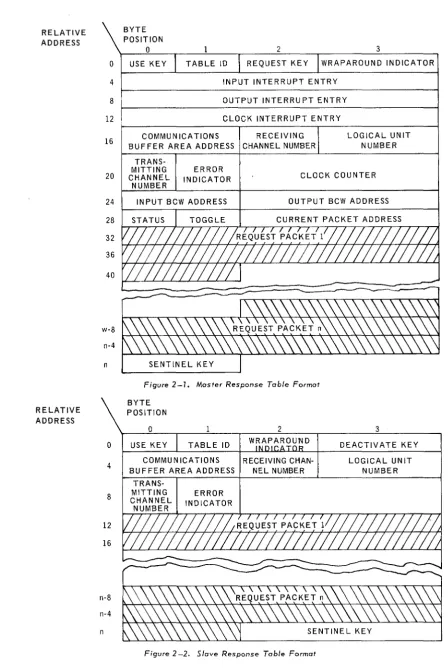
2.2. RESPONSE TABLE
The Response Table describes a communications file for the problem program and the Communications routine. If more than one slave computer is communicating with the master computer, one Response Table for each must be defined within the master program.
The formats for a master and a slave Response Table are shown in Figures 2-1 and
2-2. A description of the contents and use of the bytes follow the table formats.
UP-7611 UN IV AC 9200/9300
9200/9300
TO9200/9300
COMMUNICA TIONS RELATIVE ADDRESS BYTE POSITION2
SECTION:2 3
TABLE ID REQUEST KEY WRAPAROUND INDICATOR
RELATIVE ADDRESS 4 8 12 16
INPUT INTERRUPT ENTRY
OUTPUT INTERRU PT ENTRY
CLOCK INTERRUPT ENTRY
COMMUNICATIONS RECEIVING
BUFFER AREA ADDRESS CHANNEL NUMBER
TRANS-MITTING ERROR
LOGICAL UNIT NUMBER
20 CHANNEL INDICATOR CLOCK COUNTER
24 28 32 36 40 w-8 n-4 n
o
4 8 12 16 n-8 n-4 n NUMBERINPUT BCW ADDRESS OUTPUT BCW ADDRESS
Figure 2 -1. Moster Response Table Format
BYTE POSITION
o
USE KEY TABLE ID
COMMUNICATIONS
ERROR INDICATOR
2
WRAPAROUND
RECEIVING CHAN-NEL NUMBER
Figure 2 -2. Slave Response Table Format
3
DEACTIVATE KEY
LOGICAL UNIT NUMBER
- 2
UP-7611
"-""
UNIVAC 9200/9300 2
9200/9300 TO 9200/9300 COMMUNICATIONS
SECTION: PAGE:
2.2.1. Use Key
This byte must be set initially to 0016' Both master and slave routines set the byte to FF16 when an interchange is taking place. When this byte is set to FF 16 , the table must not be modified by either the master or slave problem program. The slave program also checks this byte for the end-of-transmission setting 01 16 (see 3.4).
2.2.2. Table Identification
This byte con tains the iden tification assigned by the problem program to a particular Response Table. The identification must be identical within a pairing of master and slave Response Tables. The identification may be any combination of two hexa-decimal digits, 00 through FF.
2.2.3. Request Key
This byte indicates the status of the request and is set by the master routine. The slave Response Table does not contain a request key. The master program can determine the status of a request by checking this byte. The request key may have the following hexadecimal values.
Hexadecimal
Value Meaning
00 Request pending
02 Error
03 Time out
04 Program not in
OS
Program not ready12 Incorrect packet
FF Request successfully completed
A value of 02 (error) indicates an error in transmission. The request should be resubmitted.
A time out (03) occurs when the clock counter is reset during an interchange. The request should be resubmitted. The master program is notified of a time out by means of a display.
When a value of 12 (incorrect packet) occurs, a CANCL macro instruction must be executed.
2.2.4. Wraparound Indicator
Initially, this byte is set to 0016 by the problem programs. Thereafter it is used by the master and slave routines to indicate whether the upper or lower half of the communications buffer is being filled.
UP-7611 9200/9300 TO 9200/9300 COMMUNICATIONS UNIVAC 9200/9300 2
SECTION: PAGE:
2.2.5. Deactivate Key
The deactivate key indicates the availability of the Response Table to either the slave program or the slave routine. If the key is set to FF 16• the slave Response
Table is not available to the slave routine and may be altered by the slave program at this time. When the key is set to 0016. the Response Table is available to the slave routine exclusively.
The master Response Ta ble does not contain a deactivate key.
2.2.6. Input Interrupt Entry
At assembly time these bytes must contain the Branch And Link instruction
LABEL 15 OPERATION 15 OPERAND
10 16
Where: V?MI is the label of the entry to the routine processing the input interrupts.
The problem program must define V?MI in an EXTRN card. V?MI is also defined in an ENTRY card in C9MR.
This entry is not required in the slave Response Table because the slave routine maintains the information within its own environment.
2.2.7. Output Interrupt Entry
At assembly time these bytes must contain the Branch And Link instruction
I I I I I I I ,
II
BI A, L, ,111,5"
I V,? I M, 0, , , I , I , , I , , , I I , , ,where: V?MO is the label of the entry to the routine processing output interrupts.
The problem program must define V?MO in an EXTRN card. V?MO is also defined in an ENTRY card in C9MR.
This entry is not required in the slave Response Table.
I
UP-7611 9200/9300 TO 9200/9300 COMMUNICATIONS UN IV AC 9200/9300
2
SECTION:2.2.8. Clock Interrupt Entry
At assembly time these bytes must contain the Branch And Link instruction
LABEL 1; OPERATION 1; OPERAND
10 16
I I I I
I I I I
where: V?CK is the label of the entry to the routine processing clock interrupts.
The problem program must define V?CK in an EXTRN card. V?CK is also defined in an ENTRY card in C9MR.
This entry is not required in the slave Response Table.
2.2.9. Communications Buffer Area Address
PAGE:
This is the address, defined by the problem program, of a dynamic buffer area in memory into which data is read during an LT Summary Interrupt. Data is automatically transferred from the buffer area to the work area.
The buffer area must be defined as a 128-byte area and is filled at a rate of 64 bytes at a time. While the lower half is being filled, the upper half is being transferred to the work area. The upper half is filled while the lower half is being transferred. The buffer must be assigned a modulo 128 address.
2.2.10. Receiving Channel Number
This is an 8-bit binary number denoting the physical unit number of the receiving channel. The number may be an odd number from 17 to 31. The physical unit number does not have to be the same for master and slave.
2.2.11. Logical Unit Number (Device Address)
The logical unit number is an 8-bit binary number which corresponds to the logical unit number assigned to the paired line terminals in the Logical Unit Table.
2.2.12. Transmitting Channel Number
This is an 8-bit binary number denoting the physical unit number of the transmitting channel. The number may be an even number from 16 to 30. The number does not have to be the same for the master and slave computers.
2.2.13. Error Indicator
When the prefix of the data block (see 5.2.2) is not equal to 0001 16 for data received, the error indicator is set to FF 16'
2.2 14. Clock Counter
A clock counter is maintained by the master routine for timing data transfers requested by the problem program. In the slave routine, the clock counter is maintained internally.
UP-7611
UNIV AC 9200/93009200/9300
TO9200/9300
COMMUN ICA T IONS2
SECTION:2.2.15.
Input BCW AddressThe address of the input Buffer Control Word is stored in these bytes by the mas ter routine.
2.2.16.
Output BCW AddressThe address of the output Buffer Control Word is stored in these bytes by the master routine.
2.2.17.
StatusThis byte is used only by the master routine to maintain the internal status of a particular request.
2.2.18.
ToggleThis byte is used only by the master routine.
2.2.19.
Current Packet AddressPAGE:
The master program places the address of the current request packet into register
13
when it issues a request. When the master routine receives control as a result of the interrupt, it stores the address in register 13 into these bytes in the Response Table.2.2.20.
Sentinel KeyThe last two bytes in the table must contain FFFF
16
to indicate the end of the table. The relative location of the sentinel key will vary, depending on the number of request packets in the table. The request packets immediately precede the sentinel key and are ten bytes in length.2.3.
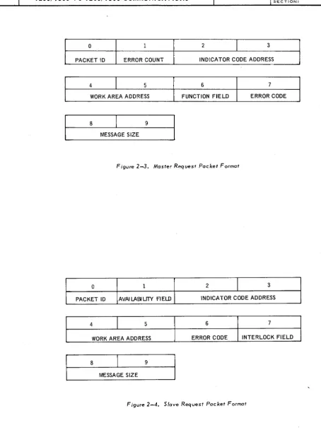
REQUEST PACKETSThe request packets are an integral part of any Response Table. The number of packets within a table may vary, and they may be deleted or inserted during the execution of a problem program. While a request is being processed, the problem programs should not delete packets from the Response Table or make an active request packet inactive.
The formats for a master and a slave request packet are shown in Figures
2-3
and2-4.
2.3.1.
Packet IdentificationThe packet identification is assigned by the problem program and is used by Doth master and slave routines to specify a particular type of interchange. The identifi-cation of the request packet in the master routine must match a corresponding request packet identification in the slave routine and must be unique. It may be any combination of binary O's and l's, but must not be alll's.
2.3.2.
Error CountThe master program must set this byte to
00
1 6 initially. For each packet, the masterroutine maintains a count of any hardware errors which occur during the processing of a packet.
---~
SECTION:
'UP-76fl UNIVAC 9200/9300
9200/9300
TO9200/9300
COMMUNICATIONS 2 PAGE: 7o
2 3PACKET ID ERROR COUNT INDICATOR CODE ADDRESS
~---~---~---~--~---~
4 5 6 7
WORK AREA ADDRESS FUNCTION FIELD ERROR CODE
8
I
9MESSAGE SIZE
Figure 2-3. Master R"'quest Packet Format
o
2 3PACKET ID AVAI LABI LrTY FI ELD INDICATOR CODE ADDRESS
4 5 6 7
WORK AREA ADDRESS ERROR CODE INTERLOCK FIELD
8
I
9MESSAGE SIZE
UP-7611
9200/9300
UN IVAC 9200/9300 TO 9200/9300 COMMUNICATIONS 2SECTION: PAGE:
2.3.3. Availability Field
This byte is used by the slave program to communicate the availability of a packet to the slave routine. When the slave program sets this byte to FF16' making a packet inactive, no interchange requesting that packet can take place. To make the packet active and available to the slave routine again, the slave program must set this byte to 00 16,
2.3.4. Indicator Code Routine Address
These two bytes contain the address of a routine in the problem program (master or slave, or both) that is to be executed at the completion of an interchange. The indicator code routine is executed in I/O program state; therefore, execution time should be minimized. GET or PUT macro instructions must not be issued by an indicator code routine. The exit from an indicator code routine should be the instruction
LABEL 11 OPERATION 11 OPERAND
10 16
I I
I
16\
C, 5 , 0(1,14) I I II I I I
The saving and restoring of any special registers is the responsibility of the problem programs. If these bytes are set to 0000 16, no indicator code routine is executed.
2.3.5. Work Area Address
The problem program must define its work area and store the address in bytes 4 and 5 of the request packet. The first two bytes of the work area are used by the Com-munications routines; therefore, the work area must be at least two bytes greater than the size of the message. If data is being sent, the Communications routine places 000116 in these two bytes. If data is being received, the Communications routine places the address of the last byte of the message being received into these two bytes before branching to any indicator code rouhne. This facilitates processing variable-length messages.
If a message exceeds the work area, the excess is stored in the next higher memory locations contiguous to the work area. Therefore, the work area should be equal to or greater than the 1011gest data message to avoid unpredictable results.
2.3.6. Function Field
This byte specifies whether the function of the request packet in a master ~esponse Table is to send data to or receive data from the slave routine.
Hexadecimal Value
00 01
Function Receive (GET) Send (PUT)
I
UP-7611
9200/9300
UN IV AC 9200/9300 TO9200/9300
COMMUN ICA T IONS 2 SECTION:2.3.7. Error Code
The various bits in this byte are used by both the master and slave routines to indicate the type of hardware error. This byte must be set initially to 00 16 by the pro blem programs.
2.3.8. Interlock Field
PAGE:
The slave routine sets this byte to FF16 at the successful completion of an inter-change. This indicates to the slave program that the requested data is available for processing in the work area. The slave routine cannot use this packet again until the slave program sets the interlock field to 00 16 , This byte is not used by the master program or master routine.
2.3.9. Message Size
In request packets containing a Send function, this byte must contain the number of bytes in the message, in binary. This number must be two greater than the actual number of data bytes to be transmitted, since the first two bytes of the message are used by the Communications routine for control purposes.
2.4. LINKING
When linking the relocatable element of C9MR to the master problem program and of C9SR to the slave problem program, the following EQU card must be submitted to the Linker.
LABEL '6 OPERATION '6 OPERAND
10 16
VL?AS I
I Ix
II I I I
where: x has the following value, depending on the type of data sets used by the system:
DATA SET* 201A3
201B1 or 202D 205B1
301B or 303C
BAUDS 2,000 2,400 4,800 50,000
VALUE OF X
1
1
1
10
*Bell Telephone Company Data Set model numbers.
UP-7611 UNIVAC 9200/9300
9200/9300
TO9200/9300
COMMUNICATIONSSECTION:
2.5. MASTER ROUTINE DISPLA YS
The format of the displays generated by the master routine (C9MR) is:
7xyy
where: 7 indicates that this display is generated by the master routine. x is the error message.
yy is the device address.
Hexadecimal
Display Reason and Action
2
71yy Parity error (includes BUS OUT, data check, overrun, and carrier off). Press the START switch to re-try five times, or key a nonzero into location 4 to cancel.
72yy
73yy
78yy
79yy
7Ayy
7Byy
File not opened.
Press the START switch to cancel.
Response Table error (for example, the communications buffer area is not mod 128).
Press the START switch to cancel. Offline.
Place the DCS online and press the START switch to re-try. Invalid function (command reject).
Press the START switch to re-try, or key a nonzero into location 4 to cancel.
Time out; clock is reset during an interchange. Press the START switch to resubmit the request. Physical unit already allocated.
Press the START switch to cancel.
10
UP-7611 9200/9300 TO 9200/9300 COMMUNICATIONS UNIVAC 9200/9300 3
SECTION: PAGE:
3. PROGRAM PROCEDURES
3.1. SCOPE
This section describes the procedures for opening a file, for sending and receiving data, and for closing a file.
3.2. OPEN
The master program must open the master routine and all associated Response Tables; the slave program must open the slave routine and its Response Table. The following macro instruction is used to open a routine.
LABEL 1) OPERATION 1) OPERAND
10 16
where: filename is C9MR for the master routine or C9SR for the slave routine.
Register 15 must be loaded with the address of the table before the OPEN macro instruction is issued. If there is more than one master Response Table, the master program must load register 15 with the address of the table and issue an OPEN macro instruction for each Response Table required.
3.3. SEND AND RECEIVE
The master program initiates all requests, whether data is to be sent or received. To initiate a request, the master program must load register 15 with the address of the appropriate Response Table, load register 13 with the address of the applicable request packet in the Response Table, and then issue either of the following macro instructions.
I : : : : : : :
II::::~
:
II::::M~
: : : : : : : : : : : : : : : : : : :
The GE T macro instruction is used to receive data from the slave program. The PUT macro instruction is used to send data to the slave program. The direction of the interchange is also specified in the function field of the request packet in the master Response Table.
!uP-7611
9200/9300
UNIVAC 9200/9300 TO9200/9300
COMMUNICATIONS 3SECTION: PAGE:
The GET or PUT macro instruction executes a Branch And Link to the master routine (C9MR). If the master routine determines that the Response Table is currently
unavailable because another request is in process, it returns control to the byte following the GET or PUT macro instruction in the master program. The master program should resubmit the request if the request is ·to be processed.
If the master routine determines that the Response Table is available, it accepts the request and returns control to the fifth byte following the GET or PUT macro instruction in the master program. The master program can then determine the status of the request from the value stored in the request key in the Response Table.
When a request is accepted, the master routine sets the request key to 0016. Acceptance of the request does not imply that it has been completed.
To determine when a request has been completed, the master program can check the request key for a value of FF 16 . If the request was a GET macro instruction, the requested data is in the work area available for processing.
Both the master and slave programs can use indicator code to determine when an interchange is completed. The Communications routines do not process an indicator code routine until the interchange is completed.
The slave program does not use the request key; it checks the interlock field to determine when an interchange is completed. The slave routine sets the interlock field to FF 16 upon the successful completion of a request. Until the slave program resets this byte to 00 16, no further interchanges requiring this particular packet are· permitted by the slave routine. The master program and routine do not use the interlock field.
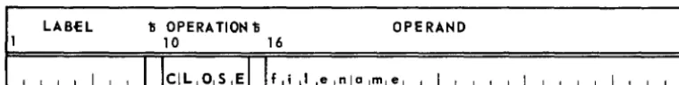
3.4. CLOSE
The master program must close the master routine and all associated Response Tables; the slave program must close the slave routine and its Response Table. The following macro instruction is used to close a routine.
LABEL 1; OPERA TIOt-l1i OPERAt-ID
10 16
where: filename is C9MR for the master or C9SR for the slave routine.
Register 15 must be loaded with the address of the Response Table before issuing the CLOSE macro instruction.
When the master program issues a CLOSE macro instruction to end communications with a particular slave program, the master routine sends an End-of-Transmission (EOT) message to the slave routine. The slave routine sets the use key in its Response
I
. UP-7611 UNIVAC 9200/9300
9200/9300 TO 9200/9300 COMMUNICATIONS 4
SECTION: PAGE:
4. PROGRAMMING CONSIDERATIONS
4.1. SCOPE
This section discusses the aspects of the coordination and interaction of the problem programs and the Communications routines that must be considered when designing a pair of master and slave programs.
4.2. PROGRAM COORDINATION
The design of a pair of problem programs, master and slave, must be so coordinated that a data message transmitted by one can be interpreted and processed by the other. When a request packet is issued by the master, there must be a corresponding request packet in the slave with a matching identity. The identification of a pair of Response Tables, master and slave, must also match.
4.3. RESPONSE TABLE AVAILABILITY
Although a problem program may check the status while a request is in process, it should not alter the Response Table until the table is available. The methods by which the problem programs may have access to the Response Table are explained in the following paragraphs.
4.3.1. Master Response Table
The master program initiates all requests; the master routine controls the processing of all requests. The master routine sets the use key to FF 16 when a request is accepted for processing. When processing is completed, the master routine resets the use key to 00 16 and sets the status of the request into the request key. Therefore, the availability of the master Response Table depends on whether the request is being initiated or processed.
4.3.2. Slave Response Table
The slave program can determine the availability of the slave Response Table by checking the following bytes:
Use Key Deactivate Key
Available Not A vaila ble
The slave program can make the table unavailable to the slave routine and thus prevent an interchange from taking place by the following procedure:
(1) Set the deactivate key to FF 16' (2) Wait until the use key becomes 0016, (3) Modify the table.
(4) Reset the deactivate key to 0016,
The slave routine can now proceed with an interchange.
UP-7611 UNIVAC 9200/9300 4
9200/9300
TO9200/9300
COMMUNICATIONS SECTION: PAGE:4.3.3. Request Packet
The slave program can determine the availability or activity of a particular request packet by checking the following bytes:
Availability Field Interlock Field
Available/ Inactive
Not A vaila ble/ Active
UP-7611 9200/9300 TO 9200/9300 COMMUNICATIONS UNIVAC 9200/9300
5
SECTION: PAGE:
5. OPERATIONAL CONSIDERATIONS
5.1. SCOPE
This section discusses operational considerations of the Communications routines and the interaction of the routines with their respective problem programs. Those functions of the routines which may be pertinent to a 9200/9300 to 9200/9300 communications system are mentioned here. These functions are not a function of the problem programs.
5.2. DATA TRANSFERS
An interchange of data between two 9200/9300 computers is accomplished by executing block transfers of data from one computer's memory to the other. Two types of blocks are transferred: control blocks and data blocks.
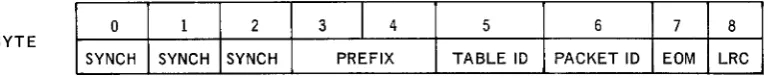
5.2.1. Control Blocks
When the master routine receives control following a GET or PUT macro instruction issued by the master program, it stores the following information in the coptrol block: the prefix code, the table identification, and the request packet identification. A control block has the following format:
BYTE 0 1 2 3
I
4 5 6 7 8 SYNCH SYNCH SYNCH PREFIX TABLE ID PACKET ID EOM LRCThe three Synchronization bytes, the End-of-Message (EOM), and the Longitudinal Redundancy Check (LRC) characters are automatically generated by a hardware function.
1
UP-7611 9200/9300 TO 9200/9300 COMMUNICATIONS UNIVAC 9200/9300 5
SECTION: PAGE:
The prefix code in bytes 3 and 4 of the control block may have the following values, depending on whether it is set by the master or slave routine.
Hexadecimal
Value Meaning
Master 010x Send (PUT) 020x Receive (GET) 030x EOT
040x Wait
Slave 0000 Acknowledge 0002 Error
0003 Proceed 0004 Program not in 0005 Program not ready
The setting for the I/O toggle is indicated by the x in the four least significant bits of the prefix code for the master control block. The master routine sets the I/O toggle.
The table identification in byte 0 of the Response Table is loaded into byte 5 of the control block. The packet identification in byte 0 of the request packet is loaded into byte 6 of the control block. Transmis;sion of the control block is then initiated.
5.2.2. Data Block
The length and contents of the data block are determined by the problem program. The data is in no way restricted, edited, or interpreted by the Communications routines. The data block has the following format.
BYTE
0 1 2 3
I
4 5 .•. n n+l n+2SYNCH SYNCH SYNCH PREFIX DATA EOM LRC
The three Synchronization bytes, the End-of-Message (EOM), and Longitudinal Redundancy Check (LRC) characters are automatically generated by a hardware function.
The prefix is set to a value of 0001 16 when either the master or the slave is sending data. When the data is received and the request is completed, the adctress of the last character received is stored in these bytes by the Communications routine. This information is transferred to the first two bytes of the work area.
UP-7611
9200/9300
UNIVAC 9200/9300 TO9200/9300
COMMUNICA TIONS 5SECTION: PAGE:
5.3. CODE GENERATION
When the problem program issues an imperative macro (OPEN, GET, PUT or CLOSE), the Assembler produces a BAL instruction whose operand addresses one in a series of BC instructions in the Communications routine. The BC instruction points to the macro label within the routine.
The imperative macro instructions produce the following source code:
LABEL 1; OPERATION 1; OPERAND
10 16
where: filename is C9MR for the master routine, or C9SR for the slave routine.
function has one of the following values:
Function OPEN CLOSE GET PUT
Value
o
4
8
16
Before issuing the macro instruction, the problem program must load register 15 with the address of the Response Table and register 13 with the address of the request packet.
The following is an example of code generation:
If the master program issues the following macro instruction
I I I I
the source code produced by the Assembler or the Preassembly Macro Pass is
I I I I I.
This instruction gives control to the master routine at byte 8, which contains an unconditional branch to the entry point for the GET subroutine.
UP-76U
9200/9300
UNIVAC 9200/9300 TO9200/9300
COMMUNICATIONS 5SECTION: PAGE:
The series of unconditional branch instructions at the beginning of the master routine which point to the various macro subroutines are:
Relative Address C9MR +4 +8
+12
+16
Ins tructionBC 15, V?OP BC 15,V?CL BC 15,V?GT
BC 15,V?PT
Function
Open Close Get
Put
The slave routine does not execute a GET or a PUT macro instruction.
5.4. INTERRUPT PROCESSING
As discussed previously, the Response Table is the link between the master program and the master routine. The operands of the three BAL instructions stored in the table by the master program contain the addresses of the input, output, and clocking interrupt routines. The OPEN subroutine in C9MR stores the Response Table address of each of these BAL instructions into the Interrupt Table, the Scan Table, and the Clocking Table.
When an interrupt occurs because the input Buffer Control Word associated with a particular Response Table is found to be active, the Supervisor transfers control to the address of the input interrupt routine paired with the input BCW. This is the address of the entry in the master Response Table containing the BAL instruction directing control to the input interrupt routine in C9MR.
Figure 5-1 illustrates the transfer of control from the address of the interrupt routine in the Scan Table to the linking instruction in the master Response Table to the input interrupt routine in C9MR, the master routine. As a result, register 15 contains the address of the Response Table when the input interrupt routine begins execution.
SCAN TABLE MASTER RESPONSE TABLE
BCW INTERRUPT USE(rABL
9
REQUESTI
WRAPAROUNDADDRESS ROUTINE ENTRY KEY ID KEY INDICATOR INPUT INTERRUPT ROUTINE
BCW INTERRUPT I
-BAL 15,V?MI
H
V?MI AH 15,V?08l
ADDRESS ROUTINE ENTRY
Entries are stored by BAL 15, V?MO Where: V?08 is defined as -8
open subroutine
Figure 5-1. Transfer of Control for an Interrupt
UP-7611
9200/9300
UNIVAC 9200/9300 TO9200/9300
COMMUNICATIONS 5SECTION: PAGE:
5.5. OPERATION OF COMMUNICATIONS MACRO ROUTINES
A brief description of the functions performed by the Communications routines when an imperative macro instruction is issued by the problem programs is given for purposes of general information.
5.5.1. C9MR Macro Routines
• OPEN - From the starting address of the Response Table stored in register 15, calculates the Response Table address of the BAL instructions for the input, output, and clocking interrupt routines. Stores these addresses into the Interrupt Table, the Scan Table, and the Clocking Table within the Supervisor.
Calculates the BCW addresses associated with the receiving and transmitting channels. Stores the addresses into the Response Table and into the Scan Table. Checks the physical unit entries associated with the logical unit numbers to ensure that they are properly alloca ted and that they contain the proper channel and unit number as specified in the receiving and transmitting channel numbers. This routine then indica tes that the Response Table is open.
• GET jPUT - Ensures that the Response Table is open and initiates the control sequence to transfer the data message to or from the work area specified in the request packet.
• CLOSE - Sends an EOT control block to the slave computer; ensures that all transmissions are completed, and marks the Response Table as closed.
5.5.2. C9SR Macro Routines
• OPEN - From the address of the Response Table stored in register 15, calculates the addresses of the interrupt entries for the transmitting and receiving channels and stores into these locations and into the Scan Table the addresses of the interrupt subroutines. Calculates the BCW addresses from the channel addresses and stores them in the Scan Table. Stores the address of the clock interrupt subroutine into the Clocking Table. Ensures that the logical units given in the Response Table are properly allocated.
• CLOSE - Ensures that all transmissions are completed and marks the Response Table as closed.