Volume 2006, Article ID 69042, Pages1–11 DOI 10.1155/ASP/2006/69042
Facial Image Compression Based on Structured
Codebooks in Overcomplete Domain
J. E. Vila-Forc ´en, S. Voloshynovskiy, O. Koval, and T. Pun
Stochastic Image Processing Group, CUI, University of Geneva, 24 rue du G´en´eral-Dufour, Geneva 1211, Switzerland
Received 31 July 2004; Revised 16 June 2005; Accepted 27 June 2005
We advocate facial image compression technique in the scope of distributed source coding framework. The novelty of the proposed approach is twofold: image compression is considered from the position of source coding with side information and, contrarily to the existing scenarios where the side information is given explicitly; the side information is created based on a deterministic approximation of the local image features. We consider an image in the overcomplete transform domain as a realization of a random source with a structured codebook of symbols where each symbol represents a particular edge shape. Due to the partial availability of the side information at both encoder and decoder, we treat our problem as a modification of the Berger-Flynn-Gray problem and investigate a possible gain over the solutions when side information is either unavailable or available at the decoder. Finally, the paper presents a practical image compression algorithm for facial images based on our concept that demonstrates the superior performance in the very-low-bit-rate regime.
Copyright © 2006 Hindawi Publishing Corporation. All rights reserved.
1. INTRODUCTION
The urgent demand of efficient image representation is rec-ognized by the industry and research community. Its neces-sity is highly increased due to the novel requirements of many authentication documents such as passports, ID cards, and visas as well as recent extended functionalities of wireless communication devices. The document, ticket, or even en-try pass personalization are often requested in many authen-tication or identification protocols. In most cases, classical compression techniques developed for generic applications are not suitable for these purposes.
Wavelet-based [1,2] lossy image compression techniques [3–6] have proved to be the most efficient from the rate-distortion point of view for the rate range of 0.2–1 bits per pixel (bpp). The superior performance of this class of algo-rithms is justified by both decorrelation and energy com-paction properties of the wavelet transform and by the effi-cient adaptive both interband (zero trees [5]) and intraband (estimation quantization (EQ) [7,8]) models that describe the data in the wavelet subbands. Recent results in wavelet-based image compression show that some modest perfor-mance improvement (in terms of peak signal-to-noise ratio (PSNR) up to 0.3 dB) could be achieved either taking into account the nonorthogonality of the transform [9] or using more complex higher-order context models of wavelet coef-ficients [10].
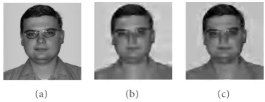
During years, a standard benchmark database of im-ages for wavelet-based compression algorithm evaluation was used. It includes several 512×512 grayscale test images (like Lena, Barbara, Goldhill) and the verification was per-formed for the rates 0.2–1 bpp. In some applications, which include person authentication data like photo images or fin-gerprint images, the operational conditions might be differ-ent. In this case, especially for strong compression (below 0.15 bpp), the resulting image quality of the state-of-the-art algorithms is not satisfactory enough (Figure 1). Therefore, for this kind of applications more advanced techniques are needed to satisfy the fidelity constrains.
(a) (b) (c)
Figure1: (a) 256×256 8-bit test imageSlava. Results of compres-sion with rate 0.071 bits per pixel (bpp) using (b) JPEG2000 stan-dard software (PSNR is 25.09 dB) and (c) state-of-the-art EQ coder (PSNR is 26.36 dB).
{X,Y}
p{x,y} X
Y
NRX
NRY EncoderX
EncoderY
Joint decoder
Figure2: Slepian-Wolf coding.
of the original image should be directly available at the de-coder. This situation is typical for the distributed coding in the remote sensing applications or can be simulated as in the case of analog and digital television simulcast [11]. In the case of single-source compression, the side information is not directly available at the decoder.
The main goal of this paper consists in the develop-ment of a concept of single-source compression within a distributed coding framework usingvirtuallycreated side in-formation. This concept is based on the accurate approxi-mation of a source data using a structured codebook, which is shared by the encoder and decoder, and the communica-tion of the residual approximacommunica-tion term within the classical wavelet-based compression paradigm.
The paper is organized as follows. InSection 2, funda-mentals of source coding with side information are pre-sented. In Section 3, an approach for single-source dis-tributed lossy coding is introduced. A practical algorithm for a very-low-bit-rate compression of passport photo images is developed inSection 4.Section 5contains the experimental results andSection 6concludes the paper.
Notation 1. Scalar random variables are denoted by capital lettersX, bold capital lettersXdenote vector random variables, lettersxandxare reserved to denote the realization of scalar and vector random variables, respectively. The superscriptNis used to denoteN-length vectorsxN = x = {x
1,x2,. . .,xN}, where theith element is denoted asxi.X∼pX(x)orX∼p(x)
indicates that a random variableXis distributed according to
pX(x). The mathematical expectation of a random variable
X ∼ pX(x)is denoted byEpX[X]orE[X].H(X),H(X,Y),
H(X | Y)denote the entropy of the random variableX, the joint entropy of the random variablesXandY, and the condi-tional entropy of the random variableXgivenY, respectively. ByI(X;Y)andI(X;Y |Z), we denote the mutual information
X Encoder i Decoder X
∈ {1,2, . . . ,2NRX}
Figure3: Lossy source coding system without side information.
between the random variablesX andY, and the conditional mutual information between the random variablesX and Y
given the random variableZ, respectively.RXdenotes the rate of communications for the random variableX. Calligraphic font
Xis used to indicate setsX ∈X, and|X|indicates the car-dinality of a set.R+is used to represent the set of positive real numbers.
2. DISTRIBUTED CODING OF CORRELATED SOURCES
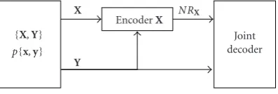
2.1. Slepian-Wolf encoding
Assume that it is necessary to encode two discrete-alphabet pair wisely independent and identically distributed (i.i.d.) random variablesXandYwith joint distributionpXY(x,y)=
N
k=1pXkYk(xk,yk). A Slepian-Wolf [12,13] code allows
per-forming lossless encoding ofXandYindividually using two separate encoders, and the decoding is performed jointly as presented inFigure 2. Using a random binning argument, it was shown that the efficiency of such a code is the same as in the case when joint encoding is used. It means that the en-coder bit rates pair (RX,RY) is achievable when the following
relationships hold:
RX≥H(X|Y),
RY≥H(Y|X),
RX+RY≥H(X,Y).
(1)
2.2. Lossy compression with side information
In the lossy compression setup, it is necessary to achieve the minimal possible distortions for a given target coding rate. Depending on the availability of side information, several possible scenarios exist [14].
No side information is available
Imagine that it is needed to represent an i.i.d. source se-quenceX ∼ pX(x),X ∈ XN using the encoding mapping fE :XN → {1, 2,. . ., 2NRX}and the decoding mapping fD :
{1, 2,. . ., 2NRX} →XN with the minimum average bit rateR
bits per element. The fidelity of representation is evaluated using the average distortion D = (1/N)Nk=1E[d(xk,xk)], where the distortion measured(x,x) is determined in general as a mappingXN×XN →R+. Due to Shannon [12,15], it is well known that the optimal performance of such a com-pression system (Figure 3) (the minimal achievable rate for certain distortion level) is determined by the rate-distortion function,
RX(D)= min
p(x|x):x,xp(x|x)d(x,x)≤D
{X,Y}
p{x,y}
X NRX
EncoderX
Y
Joint decoder
Figure4: Wyner-Ziv coding.
Side information is available only at the encoder
In this case, the performance limits coincide with the pre-vious case and the rate-distortion function could be deter-mined using (2) [16].
Side information is available only at the decoder (Wyner-Ziv coding)
Fundamental performance limits of source coding systems with side information available only at the decoder (Figure 4) were established by Wyner and Ziv [12,17]. The Wyner-Ziv problem could be formulated in the following way: given the side information only at the decoder, what will be the mini-mum rateRXnecessary to reconstruct the sourceXwith
av-erage distortion less than or equal to a given distortion value D? By other words, assume that we have a sequence of in-dependent drawings of pairs{Xk,Yk}of dependent random variables,{X,Y} ∼ p(x,y), (X,Y) ∈ XN ×YN. Our goal is to construct anRX-bits-per-element encoder fE :XN →
{1, 2,. . ., 2NRX} and joint decoder fD : {1, 2,. . ., 2NRX} × YN → XN such that the average distortion satisfies the fi-delity constraint:
EdX,fDY,fE(X) = x,x
p(x,y)px|x,y≤D. (3)
Using the asymptotic properties of random codes, it was shown [17] that the set of achievable rate-distortion pairs of such a coding system will be bounded by the Wyner-Ziv rate-distortion function:
RX(D)WZX|Y =p(u|xmin)p(x|x,y)
IU;X)−I(U;Y), (4)
where the minimization is performed over all p(u|x)p(x| x,y) and all decoder functions fDsatisfying the fidelity con-straint (3).Uis an auxiliary random variable such that|U| ≤ |X|+ 1 andY →X→Uforms a Markov chain. Hence, (4) could be rewritten as follows:
RX(D)WZX|Y = min
p(u|x)p(x|x,y)I(U;X|Y), (5)
where the minimization is performed over all p(u|x)p(x| x,y) subject to the fidelity constraint (3).
It is worth to note that for the case of zero distortions, the Wyner-Ziv problem corresponds to the Slepian-Wolf prob-lem, that is,RX(0)WZX|Y =H(X|Y).
{X,Y}
p{x,y} X
Y
NRX EncoderX
Joint decoder
Figure5: Berger-Flynn-Gray coding.
Lossy compression of correlated sources (Berger-Flynn-Gray coding)
This problem was investigated by Berger [18] and Flynn and Gray [19], and the general scheme is presented inFigure 5.
As in the previous case, Berger-Flynn-Gray coding refers to the sequence of pairs{X,Y} ∼p(x,y), (X,Y)∈XN×YN, where nowYis available at both encoder and decoder, while in the Wyner-Ziv problem it was available only at the de-coder. It is necessary to construct an RX-bits-per-element
joint coder fE:XN×YN → {1, 2,. . ., 2NRX}and a joint
de-coder fD :{1, 2,. . ., 2NRX} ×YN → XN such that the
aver-age distortion satisfiesE[d(X,fD(Y,fE(X,Y)))]≤D. In this case, the performance limits are determined by the condi-tional rate-distortion function,
RX(D)BFGX|Y =pmin(x|x,y)I X;X|Y
, (6)
where the minimization is performed over allp(x|x,y) sub-ject to the fidelity constraint (3). The Berger-Flynn-Gray rate in (6) is, in general, smaller than the Wyner-Ziv rate (5) since the availability of the correlated sourceYat both encoder and decoder makes possible to reduce the ambiguity aboutX.
Comparing the rate-distortion performance of different coding scenarios with the side information, it should be noted that, in general, the following inequalities hold [20]:
RX(D)≥RX(D)WZX|Y ≥RX(D)BFGX|Y. (7)
The last inequality becomes equality, that is, RX(D)WZX|Y = RX(D)BFGX|Y, only for the case of Gaussian distribution of the sourceXand mean square error (MSE) distortion measure. For any other pdf, performance loss exists in the Wyner-Ziv coding. It was shown in [20] that this loss is upper bounded by 0.5 bit,
RX(D)WZX|Y −RX(D)BFGX|Y ≥0.5. (8)
X Main encoder Transition detection Y
i
j X
Index encoder
Decoder
Shape codebook
Figure6: Block diagram of single-source distributed coding with side information.
(a)
(b)
(c)
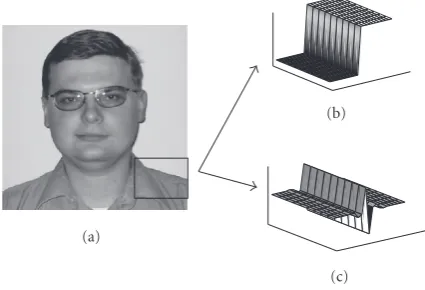
Figure7: (a) Test imageSlavaand its fragment (marked by square): two-region modeling of the fragment, (b) in the coordinate domain, and (c) in the nondecimated wavelet transform domain.
3. PRACTICAL APPROACH: DISTRIBUTED SOURCE CODING OF A SINGLE SOURCE
3.1. Coding block diagram
The block diagram of a practical single-source distributed coding system with side information is presented inFigure 6. The system consists of two main functional parts. The first part includes the main encoder that is working as a classical quantization-based lossy coder with varying rates. The sec-ond part includes the block of transition detection that ap-proximates the image edges and creates some auxiliary image
Y, as a close approximation toX. The index encoder com-municates the parameters of approximation model to the coder. The shape codebook is shared by both transition de-tection block and decoder.
The intuition behind our approach is based on the as-sumption that natural images in the coordinate domain can be represented as a union of several stationary regions of dif-ferent intensity levels or in the nondecimated wavelet trans-form domain [23] using edge process (EP) model. This as-sumption and the EP model have been used in our previous work in image denoising where promising results have been reported [24].
Under the EP model, an image in the coordinate domain (Figure 7(a)) is composed of a number of nonoverlapping smooth regions (Figure 7(b)). Accordingly, in the critically sampled or nondecimated wavelet transform domain, it is represented as a union of two types of subsets: the first one contains all samples from flat image areas, while the second
y1(1)y2(1). . .yJ(1) y1(i)y2(i). . .yJ(i) y1(M)y2(M). . .yJ(M)
Shape coset 1 Shape coseti Shape cosetM
· · · · · · · · · · · · · · · Shape indexj
Figure8: Shape cosets from the shape codebookY.
one represents edges and textures. It is supposed that the samples from the latter subset propagate along the transition direction (Figure 7(c)). Accurate tracking of the region sep-aration boundary in the coordinate domain setup or transi-tion profile propagatransi-tion in the transform domain setup al-lowed to achieve image denoising results that are among the state-of-the-art for the case of AWGN [24].
3.2. Codebook construction
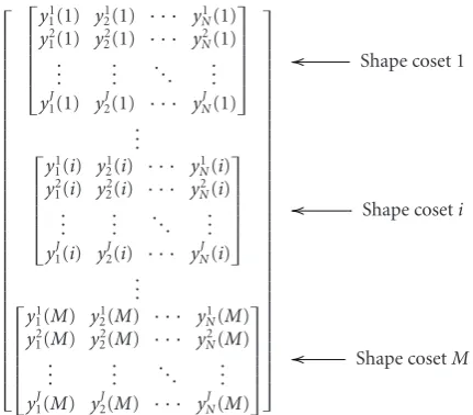
Contrarily to the image denoising setup, in the case of lossy wavelet-based image compression we are interested in con-sidering not the behavior of edge profile along the direction of edge propagation, but the different edge profiles. Due to the high variability of edge shapes in real images and the corresponding complexity of the approximation problem, we will exploit a structured codebook for shape representation. It means that several types of shapes will be used to con-struct a codebook where each codeword represents one edge of some magnitude. A schematic example of such a code-book is given inFigure 8, where several different edge profiles are exploited for image approximation. This structured code-book has a coset-based structure, where each coset contains the selected triple of edge profiles of a certain amplitude.
More formally, the structured codebook Y = {y(i)}, wherei =1, 2,. . .,M, and a coset (9) can be represented as inFigure 9:
y(i)= ⎧ ⎪ ⎪ ⎪ ⎪ ⎪ ⎨ ⎪ ⎪ ⎪ ⎪ ⎪ ⎩
y1
1(i) y12(i) · · · yN1(i) y2
1(i) y22(i) · · · yN2(i) ..
. ... . .. ... yJ1(i) y2J(i) · · · yNJ(i)
⎫ ⎪ ⎪ ⎪ ⎪ ⎪ ⎬ ⎪ ⎪ ⎪ ⎪ ⎪ ⎭
. (9)
Here,yj(i) represents the shapejfrom the shape coseti. All shape cosetsiconsist of the same shape profiles, that is,j ∈ {1, 2,. . .,J}, andi∈ {1, 2,. . .,M}for the example presented inFigure 8.
⎡ ⎢ ⎢ ⎢ ⎢ ⎢ ⎢ ⎢ ⎢ ⎢ ⎢ ⎢ ⎢ ⎢ ⎢ ⎢ ⎢ ⎢ ⎢ ⎢ ⎢ ⎢ ⎢ ⎢ ⎢ ⎢ ⎢ ⎢ ⎢ ⎢ ⎢ ⎢ ⎢ ⎢ ⎢ ⎣ ⎡ ⎢ ⎢ ⎢ ⎢ ⎢ ⎣ y1
1(1) y12(1) · · · y1N(1) y2
1(1) y22(1) · · · y2N(1)
..
. ... . .. ...
y1J(1) y2J(1) · · · yJN(1) ⎤ ⎥ ⎥ ⎥ ⎥ ⎥ ⎦ .. . ⎡ ⎢ ⎢ ⎢ ⎢ ⎢ ⎣ y1
1(i) y21(i) · · · yN1(i) y2
1(i) y22(i) · · · yN2(i)
..
. ... . .. ...
y1J(i) y2J(i) · · · yNJ(i) ⎤ ⎥ ⎥ ⎥ ⎥ ⎥ ⎦ .. . ⎡ ⎢ ⎢ ⎢ ⎢ ⎢ ⎣ y1
1(M) y12(M) · · · y1N(M) y2
1(M) y22(M) · · · y2N(M)
..
. ... . .. ...
y1J(M) y2J(M) · · · yJN(M) ⎤ ⎥ ⎥ ⎥ ⎥ ⎥ ⎦ ⎤ ⎥ ⎥ ⎥ ⎥ ⎥ ⎥ ⎥ ⎥ ⎥ ⎥ ⎥ ⎥ ⎥ ⎥ ⎥ ⎥ ⎥ ⎥ ⎥ ⎥ ⎥ ⎥ ⎥ ⎥ ⎥ ⎥ ⎥ ⎥ ⎥ ⎥ ⎥ ⎥ ⎥ ⎥ ⎦
Shape coset 1
Shape coseti
Shape cosetM
Figure9: Structured codebook: shape coset indexi(or magnitude) is communicated explicitly by the main encoder as transition lo-cation and magnitude of quantized coefficients, and shape index j
(j∈ {1, 2,. . .,J}) is encoded by index encoder.
might be used. The intuition behind this approach could be explained using the coarse-fine quantization framework pre-sented inFigure 10.
It means that for the case of high compression ratios, when there is not much rate to code the shape index, a single shape profile will be used (like a coarse quantizer). In other regimes (at medium or at high rates), it is possible to improve the fidelity of approximation adding more edge shapes to the codebook. In this case, we could assume that the high-rate quantization assumption becomes valid.
The task of real edge approximation according to the shape codebook can be formulated, for instance, like a clas-sical2norm approximation problem,
yj(i)= argmin
{yj(i)}, 1≤i≤M, 1≤j≤J
x−yj(i)2
, (10)
where the minimization is performed over the whole code-book in each image point.
3.3. Practical implementation: high-, medium-, and low-bit-rate regimes
It is clear that in the presented setup, the computational com-plexity of image approximation in each point will be signif-icant, and can be unacceptable in some realtime application scenarios. To simplify the situation, searching space dimen-sionality might be significantly reduced using techniques that simplify the edge localization. Canny edge detector [26] can be used for this purpose.
The edge of a real image could be considered as a noisy or distorted version of the corresponding codeword {y1j(i),y2j(i),. . .,yNj(i)} (edge shape) with respect to the codebook Y, that is, some correlation between an original
Shape coseti
Com p r. ra ti o Coarse codebook Fine codebook
Figure10: Successive refinement codebook construction.
edge and a codeword can be assumed. Therefore, the struc-ture of the codebook is similar to the strucstruc-ture of a channel coset code [27], meaning that the distance between code-words of equal magnitude (Figure 8) in the transform do-main should be large enough to perform correct shape ap-proximation.
The coding strategy can be performed in a distributed manner. In general, the main encoder performs the quanti-zation of the edge and communicates the corresponding in-dices of reconstruction levels to the decoder. This informa-tion is sufficient to determine the shape coset indexiat the decoder for different compression regimes, including even very-low-bit-rate regime (besides the case when quantiza-tion to zero is performed). The indexjof edge shape within a coset is communicated by the index encoder to the coder. Having the coset index and the shape index, the de-coder looks in the coset biniforyj(i) and generates the re-production sequencex = fD(x(i),yj(i)), wherex(i) is the
data reproduced at the decoder based only on the indexi. In the case of high rates, the main encoder performs a high-rate (high-accuracy) approximation of the image edges. It means that the index encoder does not produce any output, that is, both edge magnitude and edge shape could be recon-structed directly from the information contained in the main decoder bit stream. Therefore, the role of side information represented by the fine codebook consists in the compensa-tion of quantizacompensa-tion noise influence.
For middle rates, the edge magnitude prediction is still possible using the main encoder bitstream. However, the edge shape approximation accuracy for this regime is not high enough to estimate the edge shape and its index should be communicated to the decoder by the index encoder. One can note that in such a way we end up with vector-like edge quantization using the off-line designed edge codebook. The role of the side information remains similar to the previ-ous case and targets the compensation of quantization er-ror.
reconstruction is possible even when the edge coefficients in some subbands are completely discarded by the deadzone quantization.
The practical aspects of implementation of the presented single source coding system with side information are out of the scope of the paper. In the following section, we will present an application of the proposed framework to the very-low-bit-rate compression of passport photo images.
4. DISTRIBUTED CODING OF IMAGES WITH SYMMETRIC SIDE INFORMATION: COMPRESSION OF PASSPORT PHOTOS AT VERY LOW BIT RATES
In this section, the case of single source distributed coding system with side information is discussed for the case of very-low-bit-rate (less than 0.1 bpp) compression of passport photo images. The importance of this task is justified by the urgent necessity to store personal information on the capac-ity restricted media authentication documents that include passports, visas, ID cards, driver licenses, and credit cards us-ing digital watermarks, barcodes, or magnetic strips. In this paper, we assume that the images of interest are 8-bit gray scale images of 256×256 size. As it was shown inFigure 1, existing compression tools are unable to provide the satisfac-tory quality solution to this task.
The scheme presented inFigure 6is used as a basic setup for this application. As it was discussed earlier, for the case of very-low-bit-rate regime, only one shape profile (simple step edge) is exploited. Therefore, index encoder is not used in this particular case since only one index is possible as its output and, therefore, it is known a priory by the decoder. Certainly, better performance can be expected if one approxi-mates transitions using complete image codeword (Figure 6). The price to pay for that is additional log2J bits of side in-formation per shape, whereJ is the number of edge shapes within each coset.
In the next subsections, we discuss in details the particu-larities of encoding and decoding at the very-low-bit rates.
4.1. Transition detection
Encoding
Due to the fact that high-contrast edges consume a signifi-cant amount of the allocated bit budget for the complete age storage, it would be beneficial from the reconstructed im-age quality perspective to reduce the ambiguity about these image features.
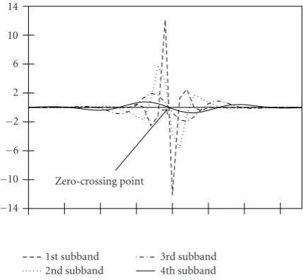
On the first step, the position of the principal edges (the edges with the highest contrast) is detected using the Canny edge detector. Due to the fact that the detection result is not always precise (some position deviation is possible), ac-tual transition location is detected using the zero-crossing concept.
Zero-crossingconcept is based on the fact that in the non-decimated wavelet transform domain (algorithma trois[23]
14
10
6
2
−2
−6
−10
−14
Zero-crossing point
1st subband 2nd subband
3rd subband 4th subband
Figure11: Zero-crossing concept: 4-level decomposition of the step edge in the nondecimated domain.
is used for its implementation) all the representations of an ideal step edge from different decomposition levels in the same spatial orientation cross the horizontal axis in the same point referred to as thezero-crossingpoint (Figure 11). This point coincides with a spatial position of the transition in the coordinate domain. Besides, the magnitudes of princi-ple peaks (maximum and minimum values of the data in the vicinity of transition in the nondecimated domain) of the components are related pairwise from high to low fre-quencies with certain fixed ratios which are known in ad-vance. Therefore, when the position of thezero-crossingpoint is given and, at least, one of the component peak magnitudes is known from original step edge, it is possible to predict and to reconstruct the missing data components with no error.
Consequently, if it is known at the decoder that an ideal step edge with a given amplitude is presented in a given image location, it is possible to assign zero rate to the predictable coefficients at the encoder, allowing higher quality recon-struction of unpredictable information.
Decoding
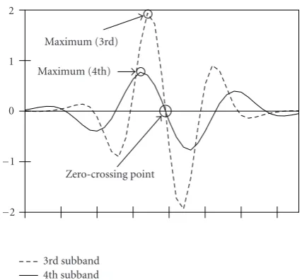
For this mode, it is assumed that the low-resolution version of the original data obtained using main encoder bitstream is already available. Detection of the coarse positions of main edges is performed on the interpolated image analogically to the encoder case. To adjust detection results, a new concept ofzero-crossingdetection is used.
2
1
0
−1
−2
Zero-crossing point Maximum (3rd)
Maximum (4th)
3rd subband 4th subband
Figure12: Zero-crossing concept: decoding stage.
edges propagating in all the subbands could be detected in such a way.
In order to reconstruct high-frequency subbands, both edge position and edge magnitude are predicted using low-frequency subbands. In Figure 12, the position of the zero-crossing point is estimated based on the data from the 3rd and 4th subbands. Having their maximum magnitude values, the reconstruction of high frequency subbands can be performed accurately based on the fixed magnitude rela-tionships (Figure 11).
4.2. Main encoder
To justify the main encoder structure, we would like to point out that the main gain achieved recently in wavelet-based lossy transform image coding is due to the accuracy of the underlying stochastic image model.
One of the most efficient and accurate stochastic im-age models that represent imim-ages in the wavelet transform domain is based on the parallel splitting of the Laplacian source firstly introduced by Hjorungnes et al. [28]. The main underlying assumption here is that global i.i.d. zero-mean Laplacian data can be represented, without loss according to the Kullback-Leibler divergence, using an infinite mixture of Gaussian pdfs with zero-mean and exponentially distributed variances,
λ 2e
(−λ|x|)= ∞
0 1 √
2πσ2e (x2/2σ2)
λe(−λσ2)dσ2, (11)
whereλis the parameter of the Laplacian distribution. The Laplacian distribution is often used to model the global statistics of the high-frequency wavelet coefficients [8,21, 22].
Hjorungnes et al. [28] were the first who demonstrated that, if the side information (the local variances) are available
at both encoder and decoder, the gain in the rate-distortion sense of coding the Gaussian mixture instead of the global Laplacian source is given by
RL(D)−RMG(D)≈0.312 bit/sample, (12)
whereRL(D) andRMG(D) denote the rate-distortion func-tions for the global i.i.d. Laplacian source and the Gaussian mixture, respectively.
The practical problem of the side information commu-nication to the decoder was elegantly solved in [7,8]. The developed EQ coder is based on the assumption of the slow varying nature of the local variances of the high-frequency subband image samples. As a consequence, this variance can be accurately estimated (predicted) given its quantized causal neighborhood.
According to the EQ coding strategy, the local variances of the samples in the high-frequency wavelet subbands are es-timated based on the causal neighborhood using maximum likelihood strategy. When it is available, the data from the parent subband are also included to enhance the estimation accuracy.
At the end of the estimation step, the coefficients are quantized using a uniform threshold quantizer selected ac-cordingly to the results of the rate-distortion optimization. In particular, the Lagrange functional should be minimized, that on the sample level is given by
yi=ri+λdi, (13)
whereriis the rate corresponding to the entropy of the quan-tizer output applied to theith sample,diis the corresponding distortion, andλis the Lagrange multiplier. The encoding of the quantized data is performed using the bin probabilities of the quantizers, where the samples fall, by an arithmetic coder.
While at the high-rate regime the approximation of the local variance field by its quantized version is valid, in the case of low rates it fails. The reason for that is the quantiza-tion to zero most of the data samples that makes local vari-ance estimation extremely inaccurate.
The simple solution proposed in [7,8] consists in the placement of all the coefficients that fall into the quantizer deadzone in the so-calledunpredictable class, and the rest in the so-called predictable class. The samples of the first one are considered to be distributed globally as an i.i.d. general-ized Gaussian distribution, while the infinite Gaussian mix-ture model is used to capmix-ture the statistics of the samples in the second one. This separation is performed using a sim-ple rate-dependent thresholding operation. The parameters of the unpredictable class are exploited in the rate-distortion optimization and are sent to the decoder as side informa-tion.
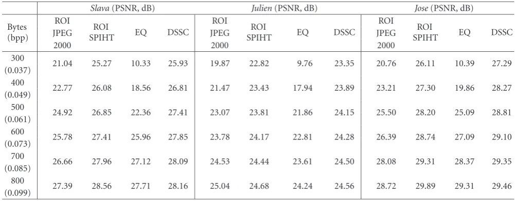
Table1: Benchmarking of the developed compression method versus existing lossy encoding techniques.
Slava(PSNR, dB) Julien(PSNR, dB) Jose(PSNR, dB)
Bytes (bpp)
ROI
ROI
SPIHT EQ DSSC
ROI
ROI
SPIHT EQ DSSC
ROI
ROI
SPIHT EQ DSSC
JPEG JPEG JPEG
2000 2000 2000
300
21.04 25.27 10.33 25.93 19.87 22.82 9.76 23.35 20.76 26.11 10.39 27.29 (0.037)
400
22.77 26.08 18.56 26.81 21.47 23.43 17.94 23.89 23.21 27.30 19.86 28.27 (0.049)
500
24.92 26.85 22.36 27.41 23.07 23.81 21.86 24.15 25.50 28.20 25.09 28.81 (0.061)
600
25.78 27.41 25.96 27.85 23.78 24.17 22.81 24.28 26.39 28.74 27.09 29.10 (0.073)
700
26.66 27.96 27.12 28.09 24.53 24.44 23.61 24.50 28.08 29.31 28.37 29.35 (0.085)
800
27.39 28.56 27.71 28.16 25.04 24.68 24.24 24.56 28.72 29.89 29.31 29.46 (0.099)
(a) (b)
Figure13: Test imageSlava: (a) region of interest and (b) back-ground four-quadrant splitting.
Motivated by the EQ coder performance, we designed our main encoder using the same principles with several modifications as follows:
(i) at the very-low-bit-rate regime, most of the informa-tion at the first and the second wavelet decomposiinforma-tion levels is quantized to zero. We assume that all the data about strong edges could be reconstructed with some precision using the side information and do not allo-cate any rate to these subbands;
(ii) high-frequency subbands of the third decomposition level are compressed using a region of interest strategy (Figure 13(a)), where the region of interest is indicated using three extra bytes. The image regions outside of the region of interest will be reconstructed using low-frequency information, and four extra bytes for the mean brightness of the background of the photo im-age in four quadrants (Figure 13(b));
(iii) a 3×3 causal window is applied for local variance es-timation;
(iv) no parent dependencies are taken into account on the stochastic image model, and only samples from the given subband are used [29].
The actual bitstream from the encoder is constituted by the data from the EQ encoder, three bytes determining the
position of the rectangular region-of-interest, and four bytes characterizing the background brightness.
4.3. Index encoder
As it was mentioned in the previous subsection, only one edge profile (the step edge) is used at the very-low-rate regime. Thus, index encoder does not produce any output.
4.4. Decoder
The decoder performs the reconstruction of the compressed data using the main encoder output and the available side information. The bitstream of the main encoder is decom-pressed by the EQ decoder. The fourth wavelet transform de-composition level is decompressed using classical algorithm version, and the third level is reconstructed using region of interest EQ decoding.
Having two lowpass levels of decomposition, the low-resolution reconstruction (with two high-frequency decom-position levels equal to zero) of the original photo using wavelet transform is obtained. Final reconstruction of high-quality data is performed based on the interpolated image, and the transition detection block information in the non-decimated wavelet transform domain.
5. EXPERIMENTAL RESULTS
29
27
25
23
21
PSNR
(dB)
300 400 500 600 700 800 Bytes
ROI-JPEG 2000 ROI-SPIHT
EQ DSSC (a)
25
24
23
22
21
PSNR
(dB)
300 400 500 600 700 800 Bytes
ROI-JPEG 2000 ROI-SPIHT
EQ DSSC (b)
30
28
26
24
PSNR
(dB)
300 400 500 600 700 800 Bytes
ROI-JPEG 2000 ROI-SPIHT
EQ DSSC (c)
Figure14: Benchmarking of the developed compression method versus existing lossy encoding techniques: (a)Slava, (b)Julien, and (c)Jose
test images.
(1a) (1b) (1c) (1d) (1e) (1f) (1g) (1h) (1i)
(2a) (2b) (2c) (2d) (2e) (2f) (2g) (2h) (2i)
(3a) (3b) (3c) (3d) (3e) (3f) (3g) (3h) (3i)
Figure15: Experimental results. The first column: the original test images; the second column: ROI-JPEG2000 compression results for the rate 400 bytes; the third column: ROI-SPIHT compression results for the rate 400 bytes; the fourth column: EQ compression results for the rate 400 bytes; the fifth column: DSSC compression results for the rate 400 bytes; the sixth column: ROI-JPEG2000 compression results for the rate 700 bytes; the seventh column: ROI-SPIHT compression results for the rate 700 bytes; the eighth column: EQ compression results for the rate 700 bytes; and the ninth column: DSSC compression results for the rate 700 bytes.
The performance is evaluated in terms of the peak signal-to-noise ratio PSNR=10 log10(2552/x−x2).
The obtained results allow to conclude about the pro-posed method advantages over the selected competitors for compression rates below 0.09 bpp in terms of both visual quality and PSNR. Performance loss at higher rate in our case in comparison with ROI-SPIHT and ROI-JPEG2000 is ex-plained by the necessity of algorithm performance optimiza-tion for this rate regime that includes a modificaoptimiza-tion of the unpredictable class definition.
6. CONCLUSIONS
conclude its superiority over a number of existing encod-ing techniques at rates below 0.09 bpp in terms of both vi-sual quality and PSNR. The realized performance loss of the developed algorithm at rates higher than 0.09 bpp is justi-fied by the necessity of its parameters optimization for this rate range. This extension is a subject of our ongoing re-search.
DISCLAIMER
The information in this document reflects only the authors’ views, is provided as is and no guarantee or warranty is given that the information is fit for any particular purpose. The user thereof uses the information at its sole risk and liability.
ACKNOWLEDGMENTS
This paper was partially supported by SNF Professorship Grant no. PP002-68653/1, Interactive Multimodal Infor-mation Management (IM2) project, and by the European Commission through the IST Programme under Contract IST-2002-507932 ECRYPT and FP6-507609-SIMILAR. The authors are thankful to the members of the Stochastic Image Processing Group at University of Geneva and to Pierre Van-dergheynst (EPFL, Lausanne) for many helpful and interest-ing discussions. The authors also acknowledge the valuable comments of the anonymous reviewers.
REFERENCES
[1] I. Daubechies,Ten Lectures on Wavelets, SIAM, Philadelphia, Pa, USA, 1992.
[2] S. G. Mallat, “A theory for multiresolution signal decomposi-tion: the wavelet representation,”IEEE Transactions on Pattern Analysis and Machine Intelligence, vol. 11, no. 7, pp. 674–693, 1989.
[3] C. Chrysafis and A. Ortega, “Efficient context-based entropy coding lossy wavelet image compression,” inProceedings of Data Compression Conference (DCC ’97), pp. 241–250, Snow-bird, Utah, USA, March 1997.
[4] A. Said and W. A. Pearlman, “A new, fast, and efficient im-age codec based on set partitioning in hierarchical trees,”
IEEE Transactions on Circuits and Systems for Video Technol-ogy, vol. 6, no. 3, pp. 243–250, 1996.
[5] J. M. Shapiro, “Embedded image coding using zerotrees of wavelet coefficients,”IEEE Transactions on Signal Processing, vol. 41, no. 12, pp. 3445–3462, 1993.
[6] Z. Xiong, K. Ramchandran, and M. T. Orchard, “Space-frequency quantization for wavelet image coding,”IEEE Trans-actions on Image Processing, vol. 6, no. 5, pp. 677–693, 1997. [7] S. M. LoPresto, K. Ramchandran, and M. T. Orchard, “Wavelet
image coding via rate-distortion optimized adaptive classifica-tion,” inProceedings of NJIT Symposium on Wavelet, Subband and Block Transforms in Communications, Newark, NJ, USA, 1997.
[8] S. M. LoPresto, K. Ramchandran, and M. T. Orchard, “Image coding based on mixture modeling of wavelet coefficients and a fast estimation-quantization framework,” inProceedings of
Data Compression Conference (DCC ’97), pp. 221–230, Snow-bird, Utah, USA, March 1997.
[9] A. Deever and S. S. Hemami, “What’s your sign? efficient sign coding for embedded wavelet image coding,” inProceedings of Data Compression Conference (DCC ’00), pp. 273–282, Snow-bird, Utah, USA, March 2000.
[10] X. Wu, “Compression of wavelet transform coefficients,” in
The Transform and Data Compression Handbook, K. R. Rao and P. C. Yip, Eds., chapter 8, pp. 347–378, CRC Press LLC, Boca Raton, Fla, USA, 2001.
[11] S. S. Pradhan and K. Ramchandran, “Enhancing analog im-age transmission systems using digital side information: a new wavelet-based image coding paradigm,” inProceedings of Data Compression Conference (DCC ’01), pp. 63–72, Snowbird, Utah, USA, March 2001.
[12] T. M. Cover and J. Thomas,Elements of Information Theory, John Wiley and Sons, New York, NY, USA, 1991.
[13] D. Slepian and J. K. Wolf, “Noiseless encoding of correlated in-formation sourcea,”IEEE Transactions on Information Theory, vol. 19, no. 4, pp. 471–480, 1973.
[14] T. M. Cover and M. Chiang, “Duality between channel capac-ity and rate distortion with two sided state information,”IEEE Transactions on Information Theory, vol. 48, no. 6, pp. 1629– 1638, 2002.
[15] C. E. Shannon, “Coding theorems for a discrete source with a fidelity criterion,”Institute of Radio Engineers, International Convention Record, vol. 7 (Part 4), pp. 142–163, 1959. [16] T. Berger, Rate-Distortion Theory: A Mathematical Basis for
Data Compression, Prentice-Hall, Englewood Cliffs, NJ, USA, 1971.
[17] A. Wyner and J. Ziv, “The rate-distortion function for source coding with side information at the decoder,”IEEE Transac-tions on Information Theory, vol. 22, no. 1, pp. 1–10, 1976. [18] T. Berger, “Multiterminal source coding,” inThe Information
Theory Approach to Communications, G. Longo, Ed., Springer, New York, NY, USA, 1977.
[19] T. J. Flynn and R. M. Gray, “Encoding of correlated observa-tions,”IEEE Transactions on Information Theory, vol. 33, no. 6, pp. 773–787, 1987.
[20] R. Zamir, “The rate loss in the Wyner-Ziv problem,” IEEE Transactions on Information Theory, vol. 42, no. 6, Part 2, pp. 2073–2084, 1996.
[21] M. K. Mihcak, I. Kozintsev, K. Ramchandran, and P. Moulin, “Low-complexity image denoising based on statistical mod-eling of wavelet coefficients,”IEEE Signal Processing Letters, vol. 6, no. 12, pp. 300–303, 1999.
[22] Y. Yoo, A. Ortega, and B. Yu, “Image subband coding using context based classification and adaptive quantization,”IEEE Transactions on Image Processing, vol. 8, no. 12, pp. 1702–1715, 1999.
[23] S. G. Mallat, A Wavelet Tour of Signal Processing, Academic Press, New York, NY, USA, 1997.
[24] S. Voloshynovskiy, O. Koval, and T. Pun, “Wavelet-based age denoising using non-stationary stochastic geometrical im-age priors,” inProceedings of IS&T/SPIE’s 15th Annual Sym-posium, Electronic Imaging: Image and Video Communications and Processing 2003, vol. 5022 ofProceedings of SPIE, pp. 675– 687, Santa Clara, Calif, USA, January 2003.
IEEE International Conference on Acoustics, Speech, and Signal Processing (ICASSP ’96), vol. 4, pp. 2343–2346, Atlanta, Ga, USA, May 1996.
[26] J. Canny, “A computational approach to edge detection,”
IEEE Transactions on Pattern Analysis and Machine Intelligence, vol. 8, no. 6, pp. 679–698, 1986.
[27] J. G. Proakis, Digital Communications, McGraw-Hill, New York, NY, USA, 3rd edition, 1995.
[28] A. Hjorungnes, J. M. Lervik, and T. A. Ramstad, “Entropy coding of composite sources modeled by infinite Gaussian mixture distributions,” inProceedings of IEEE Digital Signal Processing Workshop, pp. 235–238, Loen, Norway, September 1996.
[29] K. R. Rao and P. C. Yip, Eds.,The Transform and Data Com-pression Handbook, CRC Press, Boca Raton, Fla, USA, 2000. [30] C. Christopoulos, J. Askelof, and M. Larsson, “Efficient
meth-ods for encoding regions of interest in the upcoming JPEG 2000 still image coding standard,”IEEE Signal Processing Let-ters, vol. 7, no. 9, pp. 247–249, 2000.
[31] E. Atsumi and N. Farvardin, “Lossy/lossless region-of-interest image coding based on set partitioning in hierarchical trees,” inProceedings of IEEE International Conference on Image Pro-cessing. (ICIP ’98), vol. 1, pp. 87–91, Chicago, Ill, USA, Octo-ber 1998.
J. E. Vila-Forc´enreceived the Telecommu-nications Engineer degree from the Carlos III University of Madrid, Spain, in 2001. In 2001–2002, he joined the Signal Theory and Communications Department of the Car-los III University, working in the develop-ment of the MPEG4 standard. Since 2002, he has been an Assistant Professor and a Ph.D. student at the Stochastic Image Pro-cessing Group, Computer Vision and
Mul-timedia Lab, Department of Computer Science of the University of Geneva, Geneva, Switzerland. His current research interests are the information-theoretic aspects of digital data hiding, communi-cations with side information, and stochastic image modeling for compression.
S. Voloshynovskiyreceived the Radio En-gineer degree from Lviv Polytechnic In-stitute in 1993, and the Ph.D. degree in electrical engineering from State University
Lvivska Politechnika, Lviv, Ukraine, in 1996. In 1998–1999, he has been with Univer-sity of Illinois at Urbana-Champaign, USA, as a Visiting Scholar. Since 1999, he has been with University of Geneva, Switzer-land, where he is currently an Associate
Pro-fessor with the Department of Computer Science, and Head of the Stochastic Image Processing Group. His current research interests are in information-theoretic aspects of digital data hiding, visual communications with side information, and stochastic image mod-eling for denoising, compression, and restoration. He has coau-thored over 100 journal and conference papers in these areas as well as nine patents. He has served as a consultant to private industry in the above areas.
O. Kovalreceived his M.S. Degree in elec-trical engineering from the National Uni-versityLvivska Politechnika, Lviv, Ukraine, in 1996. In 1996–2001, he was with the Department of Synthesis, Processing, and Identification of Images, Institute of Physics and Mechanics (Lviv, Ukraine) as a re-searcher and Ph.D. student. He received his Ph.D. degree in electrical engineering from the National University Lvivska
Po-litechnika, in 2002. Since 2002, he has been with Stochastic Image Processing Group, Computer Vision and Multimedia Lab, Univer-sity of Geneva, from which he received his Ph.D. degree in stochas-tic image modeling in 2004, where he is currently a Postdoctoral Fellow. His research interests cover stochastic image modeling for different image processing applications, digital watermarking, in-formation theory, and communications with side inin-formation.
T. Pun received his Ph.D. degree in im-age processing in 1982, at the Swiss Fed-eral Institute of Technology in Lausanne (EPFL). He joined the University of Geneva, Switzerland, in 1986, where he is currently a Full Professor at the Computer Science De-partment and Head of the Computer Vi-sion and Multimedia Lab. Since 1979, he has been active in various domains of im-age processing, imim-age analysis, and