Volume 2007, Article ID 98639,21pages doi:10.1155/2007/98639
Research Article
Multi-Agent Framework in Visual Sensor Networks
M. A. Patricio, J. Carb ´o, O. P ´erez, J. Garc´ıa, and J. M. Molina
Grupo de Inteligencia Artificial Aplicada, Departamento de Inform´atica, Universidad Carlos III de Madrid, Avda. Universidad Carlos III 22, Colmenarejo, Madrid 28270, Spain
Received 4 January 2006; Revised 13 June 2006; Accepted 13 August 2006
Recommended by Ching-Yung Lin
The recent interest in the surveillance of public, military, and commercial scenarios is increasing the need to develop and deploy intelligent and/or automated distributed visual surveillance systems. Many applications based on distributed resources use the so-called software agent technology. In this paper, a multi-agent framework is applied to coordinate videocamera-based surveillance. The ability to coordinate agents improves the global image and task distribution efficiency. In our proposal, a software agent is embedded in each camera and controls the capture parameters. Then coordination is based on the exchange of high-level messages among agents. Agents use an internal symbolic model to interpret the current situation from the messages from all other agents to improve global coordination.
Copyright © 2007 M. A. Patricio et al. This is an open access article distributed under the Creative Commons Attribution License, which permits unrestricted use, distribution, and reproduction in any medium, provided the original work is properly cited.
1. INTRODUCTION
Nowadays, surveillance camera systems are applied in trans-port applications, such as airtrans-ports [1,2], sea environments [3,4], railways, underground [5–9], and motorways to ob-serve traffic [10–14] in public places, such as banks, super-markets, homes, department stores [15–19], and parking lots [20–22] and in the remote surveillance of human activities such as football match attendance [23] or other activities [24–26]. The common processing tasks that commercial sys-tems perform are intrusion and motion detection [27–32] and packages detection [28,31,32]. Research in university groups tends to improve image processing tasks by generat-ing more accurate and robust algorithms for object detection and recognition [22,33–37], tracking [22, 26,33,38–41], human activity recognition [42–44], database [45–47], and tracking performance evaluation tools [48].
Third-generation surveillance systems [49] is the term sometimes used in the literature to refer to systems conceived to deal with a large number of cameras, a geographical spread of resources, many monitoring points, as well as to mirror the hierarchical and distributed nature of the human pro-cess of surveillance. From an image propro-cessing point of view, they are based on the distribution of processing capacities over the network and the use of embedded signal-processing devices to get the benefits of scalability and potential robust-ness provided by distributed systems. The main goals that are
expected of a generic third-generation vision surveillance ap-plication, based on end-user requirements, are that it should provide good scene understanding, aimed at attracting the attention of the human operator in real time, possibly in a multisensor environment, as well as surveillance information using low-cost standard components.
We have developed a novel framework for deliberative camera-agents forming a visual sensor network. This work follows on from previous research on computer vision, infor-mation fusion, and intelligent agents. Intelligence in artificial vision systems, such as our proposed framework, operates at different logical levels. First, the process of scene interpreta-tion from each sensor is enacted by an agent-camera. As a second step, the information parsed by a separate local pro-cessor is collected and fused. Finally, the surveillance process is distributed over several agent-cameras, according to their individual ability to contribute their local information to a global target solution.
proactivity, and the cooperation required among these agents to accomplish surveillance justifies the sociability of camera-agents. The intelligence produced by the symbolic internal model of camera-agents is based on a deliberation about the state of the outside world (including its past evolution), and the actions that may take place in the future. Several architec-tures inspired by different disciplines, like psychology, phi-losophy, and biology, can be applied to build agents with the ability to deliberate. Most of them are based on theo-ries for describing the behavior of individuals. They include the belief-desire-intention (BDI) model, the theory of agent-oriented programming [50], the unified theories of cogni-tion [51], and subsumpcogni-tion theory [52]. Each of these theo-ries has its strengths and weaknesses and is especially suited for particular kinds of application domains. Of these theo-ries, we have chosen the BDI model to implement the de-liberation about the images captured by the camera. Agents sociability presumes some kind of communication between agents. The most accepted agent communication schemes are those based on speech-act Theory (e.g., KQML and FIPA-ACL) [53].
The foundation for most implemented BDI systems is the abstract interpreter proposed by Rao and Georgeff[54]. Although many ad hoc implementations of this interpreter have been applied to several domains, the release of JADEX [55] is gaining acceptance recently. JADEX is an extension of JADE [56], which facilitates FIPA communications between agents, and it is widely used to implement intelligent and software agents. But JADEX also provides a BDI interpreter for the construction of agents. The beliefs, desires, and inttions of JADEX agents are defined easily in XML and Java, en-abling researchers to quickly exploit the potential of the BDI model. It is a promising technology that is likely to soon be-come an unofficial standard for building deliberative agents. Therefore, this was the technology that we chose to imple-ment our multi-agent framework.
The purpose of this paper is to show our multi-agent framework for visual sensor networks applied to surveil-lance system environments. Visual sensor networks are com-posed of different sensors that monitor an extended area. The main issue for analyzing information in this distributed environment is to progressively reduce redundancy and co-herently combine information and processing capability. In our framework, these objectives are achieved thanks to its coordination abilities, which allow a dynamic distribution of surveillance tasks among the nodes, taking into account their internal state and situation. Two types of scenarios— indoor and outdoor configurations for intrusion detection and tracking—are presented to illustrate this framework’s capability to improve the surveillance globally provided by the network. Both scenarios highlight how coordinated op-eration enhances surveillance systems. The first scenario is related to the robustness and reliability of surveillance out-put, assessed with special-purpose metrics. On the other hand, the second shows how this framework extends the network functionalities, allowing surveillance tasks to be ac-complished automatically, while the cameras are accessible at the same time for human operators. Both scenarios are
implemented using the same BDI architecture that is pre-sented inSection 4. Obviously, the only things to be changed are the current state of the world according to each camera-agent’s perception, tailored to the specific situation of each scenario. This is a very important feature in surveillance sys-tems, since we usually manage a sizeable number of visual sensors. As we have used the standard representation of a generic camera-agent using JADEX, our framework has the advantage of developing distributed surveillance systems eas-ily.
The remainder of the paper describes our multi-agent framework applied to building distributed visual sensor net-works for surveillance. First,Section 2is a survey of current distributed camera surveillance systems.Section 3describes the architecture of our framework and details the structure of the agent-cameras represented in terms of the BDI model. Section 4deals with the problem of managing information in a visual sensor network and the information exchange pro-cess between neighboring camera-agents in order to achieve a robust and reliable global surveillance task. Then, two sce-narios are presented inSection 5. This section shows the im-provements achieved by using this framework and analyzes the gain over situations where there is no coordination at all between visual sensors. Finally, the conclusions are set out in Section 6.
2. DISTRIBUTED CAMERA SURVEILLANCE SYSTEMS: A SURVEY
A typical configuration of processing modules in a camera surveillance system is composed of several stages (Figure 1).
(1) Object detection module. There are two main con-ventional approaches to object detection: “temporal diff er-ence” and “background subtraction.” The first approach con-sists of the subtraction of two consecutive frames followed by thresholding. The second technique is based on the sub-traction of a background or reference model and the current image followed by a labelling process. After applying either of these approaches, morphological operations are typically applied to reduce the noise of the image difference.
(2) Object recognition module. This module uses model-based approaches to create constraints in the object appear-ance model, for example, the constraint that people appear upright and in contact with the ground. The object recogni-tion task then becomes a process of using model-based tech-niques in an attempt to exploit this knowledge.
Object detection
Object recognition
Tracking system
Action recognition
Database module
Figure1: A generic video processing framework for an automated visual surveillance system.
developing semiautomatic tools that can help create the large set of ground truth data that is necessary to evaluate the per-formance of the tracking algorithms [48].
(4) Action recognition process. Since this process should recognize and understand the activities and behaviors of the tracked objects, it is a classification problem. Therefore, it in-volves matching a measured sequence to a precompiled li-brary of labelled sequences that represent prototypical ac-tions that need to be learnt by the system via training se-quences. There are several approaches for matching time-varying data: dynamic time warping (DTW) [59,60], HMM (hidden Markov models), Bayesian networks [61,62], and declarative models [42].
(5) A database module. The final module is related to ef-ficiently storing, indexing, and retrieving all the surveillance information gathered.
Many video surveillance systems incorporating the above techniques are currently developed and installed in real envi-ronments. Typical examples of commercial surveillance sys-tems are DETEC [15] and Gotcha [16] or [17]. They are usually based on what is commonly called motion detec-tors, with the option of digital storage of the detected events (input images and time-stamped metadata). These events are usually triggered by objects appearing in the scene. An-other example of a commercial system intended for outdoor applications is DETER [63] (detection of events for threat evaluation and recognition), which reports unusual move-ment patterns of pedestrians and vehicles in outdoor envi-ronments such as car parks. DETER consists of two parts: the computer vision module and the threat assessment module (high-level semantic recognition with off-line training and on-line threat classifier). Visual traffic surveillance for auto-matically identifying and describing vehicle behavior is pre-sented in [13]. The system uses an EKF (extended Kalman filters) as a tracking module, and also includes a semantic trajectories interpretation module. For other surveillance for different applications (e.g., road traffic, ports, and railways), see [3,6,9–11]. A vision-based surveillance system is devel-oped in [25] to monitor traffic flow on a road, but focusing on the detection of cyclists and pedestrians. The system con-sists of two main distributed processing modules: the track-ing module, which processes in real time and is placed on a pole by the roadside, and the analysis module, which is performed off-line in a PC. The tracking module consists of four tasks: motion detection, filtering, feature extraction using quasi-topological features (QTC), and tracking using
first-order Kalman filters. Many of these systems require a wide geographical distribution that calls for camera man-agement and data communication. Therefore, [6] proposes combining existing surveillance traffic systems based on net-works of smart cameras. The term “smart camera” (or “intel-ligent camera”) is normally used to refer to a camera that has processing capabilities (either in the same casing or nearby) so that event detection and event video storage can be done autonomously by the camera.
Outdoor areas
Indoor areas
Figure2: Several scenes captured by the cameras of our campus surveillance system. Notice that there are different areas to guard.
The design of a surveillance system with no server to avoid this centralization is reported in [66]. All the indepen-dent subsystems are completely self-contained, and all these nodes are then set up to communicate with each other with-out having a mutually shared communication point. As part of the VSAM project, [67] presents a multi-camera surveil-lance system based on the same idea as [68]: the creation of a network of “smart” sensors that are independent and au-tonomous vision modules. In [67], however, these sensors are able to detect and track objects, classifying the moving objects into semantic categories such as “human” or “vehi-cle” and identifying simple human movements such as walk-ing. The user can interact with the system in [67].
The surveillance systems described above take advantage of progress in low-cost high-performance processors and multimedia communications. However, they do not account for the possibility of fusing information from neighboring cameras. Current research is focusing on developing surveil-lance systems that consist of a network of cameras (monoc-ular, stereo, static, or PTZ (pan/tilt/zoom)) running the type of vision algorithms that we reviewed earlier, but also us-ing information from neighborus-ing cameras. For example, the system in [23] consists of eight cameras, eight feature server processes, and a multitracker viewer. CCN [69] (co-operative camera network) is an indoor application surveillance sys-tem that consists of a network of PTZ cameras connected to a PC and a central console to be used by a human opera-tor. A surveillance system for a parking lot application is de-scribed in [21]. It uses static camera subsystems (SCS) and active camera subsystems (ACS). The Mahalanobis distance and Kalman filters are used for data fusion for the multi-tracker, as in [23]. In [68] an intelligent video-based visual surveillance system (IVSS) is presented. This system aims to enhance security by detecting certain types of intrusion in dynamic scenes. The system involves object detection and recognition (pedestrians and vehicles) and tracking. The de-sign architecture of the system is similar to ADVISOR [7]. An interesting example of a multitracking camera surveil-lance system for indoor environments is presented in [57]. The system is a network of camera processing modules, each
of which consists of a camera connected to a computer, and a control module, which is a PC that maintains the database of the current objects in the scene. Each camera processing module uses Kalman filters to enact the tracking process. An algorithm was developed that takes into account occlusions to divide the tracking task among the cameras by assigning the tracking to the camera that has better visibility of the ob-ject. This algorithm is implemented in the control module.
As has been illustrated, a distributed multi-camera surveillance requires knowledge about the topology of the links between the cameras that make up the system in or-der to recognize, unor-derstand and track an event that may be captured on one camera and to track it across other cam-eras. Our paper presents a framework that employs a totally deliberative process to represent the information fusion be-tween neighboring cameras and to manage the coordination decision-making in the network.
3. MULTI-AGENT FRAMEWORK ARCHITECTURE
In this section we describe the components of our multi-agent framework architecture for designing surveillance sys-tems. Each agent deliberatively makes decisions to carry out the system tasks coherently with other agents, considering both the information generated in its local process and the information available in the network. Transitions between areas covered by different agents will be the most important situations in this coordination process (seeFigure 2).
Blobs-to-tracks
association Track update
Detection and image segmentation: blobs extraction
Occlusion and overlap logic
Array of local target tracks
Track extrapolation
Track management Morphological
filtering Background
computation
Update
background Detector
Images Camerai
A B C
D
Figure3: Structure of video surveillance system.
computational demands, and dependencies on the scene be-ing processed. Evolutionary computation has been success-fully applied to some stages of this process to fine-tune over-all performance [73]. The structure of these algorithms is presented inFigure 3and explained at length in [70]. To il-lustrate the process,Figure 4shows different levels of infor-mation handled in the system stages (labelled with letters A– D inFigure 3), ranging from raw images to tracks.
Second, the information extracted must be collected and fused. The multi-camera surveillance coordination problem can be solved in a centralized way: an all-knowing central entity that makes decisions on behalf of all the cameras as is suggested in [74,75]. However, a distributed solution may sometimes (due to scalability and fault-tolerance re-quirements) become an interesting alternative. Distribution is achieved through a multi-agent system, where a single soft-ware agent represents and controls each camera. Each agent only knows about some external events (partial knowledge), and has to make decisions with this limitation. Consequently, the quality of the decision cannot be optimal. Even with partial knowledge, we try to show how coordination among agents can improve the quality of decisions bringing them close to optimum.
Each camera is controlled by an agent, which will make decisions according to an internal symbolic model that rep-resents encountered situations and mental states in the form of beliefs, desires, and intentions. As we mentioned before, our multi-agent framework takes a BDI approach [54,76– 78] to modeling camera-agents. The final goal of agents is to improve the recognition and interpretation process (ob-ject class, size, location, ob(ob-ject kinematics) of mobile targets through cooperation, and, therefore, to improve the surveil-lance performance of the whole deployed camera system. The cooperation between camera-agents takes place for the purpose of improving their local information, and this is achieved by message exchange (seeFigure 5). In our domain, we suggest that the beliefs, desires, and intentions of each camera-agent are the following.
(I) Beliefs
Camera-agent beliefs should represent information about the outside world, like objects that are being tracked, other known camera-agents who are geographically close and their execution state, and geographic information, including loca-tion, size and trajectory of tracked objects, location of other elements that might require special attention, such as doors and windows, and also obstacles that could occlude targets of interest (e.g., tables, closets).
(II) Desires
Camera-agents have two main desires because the final goal of a camera-agent is the correct tracking of moving ob-jects: permanent surveillance and temporary tracking. The corresponding surveillance plan is as follows: camera-agents permanently capture images from the camera until an in-truder is detected (or announced by a warning from another camera-agent). On the other hand, the tracking plan is initi-ated by some event (detection by camera/warning from an-other agent), and it runs a tracking process internally on the images from the camera until tracking is no longer possible.
(III) Intentions
There are two basic actions: external and internal actions. Ex-ternal actions correspond to communication acts with other camera-agents that implement different cooperative dialogs, while internal actions involve commands to the tracking sys-tem, and even to the camera.
4. INFORMATION MANAGEMENT THROUGH CAMERA-AGENTS COORDINATION
(a) Original images
(b) Detected pixels
(c) Filtered images
(d) Estimated tracks
Figure4: Information levels in the processing chain. Characters from (a) to (d) are related to the modules ofFigure 3.
Agent A MSG
Agent B MSG
Agent C
Figure5: Overview of camera agents exchanging messages.
our multi-agent framework is used to achieve the following goals.
(1) To ensure that an object of interest is successfully tracked across the whole area to be guarded, assuring con-tinuity and seamless transitions. Objects of interest are able to move within the restricted area and several camera-agents share part of their fields of view. When an object of interest reaches an area shared with neighboring camera-agents, they establish a dialog in order to exchange information about the object.
(3) To manage dependences between neighboring cam-eras and carry out the network tasks for use in other activi-ties (usually surveillance tasks managed by a human opera-tor) when the network has no objects to track.
Based on these goals, we developed the surveillance process of a generic camera-agent. As we outlined before, camera-agents may run two main types of plans:surveillance andtracking. The first plan is continuously active and gov-erns the general surveillance of the camera’s field of view. This internal process (encapsulated in another Java class, and invoked from this initial surveillance plan) consists of captur-ing sequential images from the camera and observcaptur-ing poten-tial moving objects (intruders). When such an observation is made (an intrusion is suddenly detected), atrackingsubplan will then be initiated for the purpose of tracking this moving object. The tracking goal is invoked taking as parameter the identification of the object. Bearing in mind that the possible goals in JADEX are perform, maintain, achieve, and query, perform seems to be the most appropriate description of its intention.
Furthermore,trackingplans can be fired from an inter-nal event produced by thesurveillanceplan, but they can also be initiated by external events such as messages from other agents. This is the case of an accepted proposal of tracking from an agent that is geographically close (in the same room, or in a room linked by doors and windows with that room).
This tracking plan implementation starts an internal tracking process with the advantage of prior warning from the other agent, or with no prior knowledge about the object if it was initiated as a subgoal of thesurveillanceplan of the same agent.
Additionally, the internal process of tracking (ruled by the tracking plan) may lead to internal events on two grounds.
(a) The tracked moving object is close to a zone of limited vision (e.g., doors and windows), and the moving object is expected to move out of the camera’s field of view in the near future.
(b) Or the moving object is already out of camera’s field of view.
In the first case, the agent will warn the agents govern-ing the closest cameras about the expected appearance of the moving object, starting a call-for-proposals dialog that is per-formed by another subgoal:“warning about expected object dialog.”
In the second case, the agent queries other agents that could possibly view the moving object that disappeared to determine whether or not the moving object really did leave the camera’s field of view (and, therefore, whether or not the internal tracking process should be terminated). The imple-mentation of the query dialog is performed by another sub-goal:“looking for lost object dialog.”
Camera agents also require another plan to con-firm/disconfirm the presence of a given moving object when another agent submits a query about the object. This plan just evaluates whether or not the moving object is visible from the camera, and then reports the result of the evalua-tion to the other agent.
Finally, external (human) intervention would cause a querying plan to be fired (asking for permission to be tem-porarily unavailable: “requesting for a break dialog”), in a surveillance, as many warning plans would be fired as objects were currently being tracked by the agent.
In conclusion, the hierarchy of surveillance domain plans is illustrated inFigure 6.
Since these messages comply with the FIPA standard, they include a performative to represent the intention of the respective communicative act. These performatives can be: accept, agree, cancel, propose, confirm, disconfirm, failure, inform, propagate, propose, query-if, refuse, reject proposal, request, call for proposals, and so forth.
Broadly speaking, three main dialogs can take place be-tween agents.
(i) “Warning about expected object dialog.” It intends to warn the receiving agent about the expected future presence of a moving object. The goal is that the re-ceiving agent initializes a tracking plan for this moving object. This warning takes the form of a proposal. (ii) “Looking for lost object dialog.” It anticipates a
con-firmation of the presence of a moving object in the receiving agent’s field of view. It would usually com-plement the first dialog, but it can be produced stan-dalone.
(iii) “Requesting for a break dialog.”In this dialog the send-ing agent asks the receivsend-ing agent for permission to become temporarily unavailable, and objects placed in shared areas should be tracked by the receiving agent. This dialog may also include the“warning about expected object dialog,”since the receiving agent may want to warn the sending agent about its tracked ob-jects that are likely to be in the field of view of the send-ing agent accordsend-ing to its current trajectory. Finally, the receiving agent will confirm/retract its temporary unavailability.
Next, we detail some aspects about these dialogs.
4.1. Warning about expected object dialog
The first dialog would take place if agents expect some cir-cumstances in the very near future that would prevent the object from being tracked. These circumstances occur when the moving target is close to zones that cannot be tracked because they are out of the field of view of the camera con-trolled by the agent in question.
Surveillance PLAN MSG
cfp
PLAN Tracking
MSG Query-if
PLAN Querying
PLAN Warning
PLAN Informing
MSG Query-if
MSG cfp
MSG Inform
Figure6: Relationship between received messages and fired plans.
“tracking,” and “f(x)” should be determined by the receiving agent. In normal usage, the agent responding to a cfp should answer with a proposition giving the value of the precondi-tion expression. An example of this message would be
(cfp
:sender (agent ?j) :receiver (agent ?i) :content (track (object ?x)) :reply-with cfpx
)
Where variables ?i, ?j, and ?x correspond to JAVA objects, whose inclusion and extraction from FIPA messages are fa-cilitated by JADEX. In our case of surveillance, objects would allow them to be correctly identified for sending and receiv-ing agents, for instance, usreceiv-ing global positionreceiv-ing, or refer-ences to shared visual elements such as doors and windows that link one room with another.
After the reception of a cfp message, one of the receiving agents would volunteer as the tracker of the given moving object. So the next FIPA performative should be “propose” where the proposer (the sender of the proposal) informs the receiver that the proposer will adopt the intention to perform the action once the given precondition is met. Preconditions can be: the door is finally opened, the object is finally viewed by the camera, and so forth. The expression of all such possi-ble preconditions should be previously defined and shared by all agents in an ontology. An example of this message would be
(propose :sender (agent ?i) :receiver (agent ?j)
:content (track (object ?x )) (visible (object ?x)) :ontology surveillance
:reply-with proposex :in-reply-to cfpx )
Then, the receiver of the proposal (who initially sent the cfp) should accept the proposal with the corresponding FIPA performative. Accept-proposal is a general-purpose accep-tance of a proposal that has previously been submitted (typ-ically through a propose act). The agent sending the accep-tance informs the receiver that it intends the receiving agent to perform the action (at some point in the future), once the given precondition is, or becomes, true.
(accept-proposal :sender (agent ?i) :receiver (agent ?j))
:content (track (object ?x )) (visible (object ?x)) :ontology surveillance
:in-reply-to proposex )
With the acceptance of the proposal thewarning dialog between agents ends.
4.2. Looking for lost object dialog
The second dialog would often take place when some unex-pected circumstances suddenly occur: the moving agent dis-appears from a camera-agent’s field of view, but this was not predicted/observed (e.g., the moving agent may be hidden behind a closet or table). This dialog is intended to get a confirmation that another agent is viewing the moving ob-ject. Therefore, the first message is a query to a camera-agent that is the potential viewer of the moving object. The cor-responding FIPA performative is “query-if,” that is, the act of asking another agent whether (it believes that) a given proposition is true. The sending agent is requesting the re-ceiver to tell it whether the proposition is true. In our case the proposition is that the moving object is visible for the re-ceiving agent. The agent performing the query-if act has no knowledge of the truth value of the proposition, and believes that the other agent can inform the querying agent about it. So the receiving agent would answer with an “inform” FIPA communicative act:
(query-if :sender (agent ?j) :receiver (agent ?i)
:content (visible (object ?x)) :reply-with queryx
) (inform :sender (agent ?i) :receiver (agent ?j))
:content (not (visible (object ?x))) :in-reply-to queryx
)
4.3. Requesting for a break dialog
control the camera manually, for instance, to focus on some details (zoom). Therefore, all objects being tracked would be lost for a while.
This dialog intends to let other agents know about its temporary unavailability, asking about the convenience of such unavailability. The corresponding FIPA performative is “query-if,” that is, the act of asking another agent whether (it believes that) a given proposition is true. The sending agent is requesting the receiver to inform it of the truth of the propo-sition. In our case, the proposition is that there is no object coming towards the field of view of the sending agent in the very near future. The agent performing the query-if act has no knowledge of the truth value of the proposition, and be-lieves that the other agent can inform the querying agent about it. So the receiving agent would answer with an “in-form” FIPA communicative act:
(query-if :sender (agent ?j) :receiver (agent ?i)
:content (is-anyone-coming?) :reply-with queryanyone )
(inform :sender (agent ?i) :receiver (agent ?j)) :content ((object ?x))) :in-reply-to queryanyone )
Also objects placed in shared areas should be then tracked by the receiving agent. Consequently, for each object lo-cated in such a shared area that is currently being tracked by the sending agent, a cfp dialog (the first type) would take place to leave the tracking of that object to the receiving agent.
Therefore, these seven messages are the main stream of communication acts in our surveillance domain. There are also others, such as the rejection of proposals from agents in reply to cfp messages because another agent already submit-ted a proposal, other auxiliary messages due to delays, mis-understandings, and so forth, but they are not detailed here for brevity, although they also comply with the FIPA stan-dard.
5. APPLICATION SCENARIOS OF THE MULTI-AGENT FRAMEWORK
In order to illustrate the capability of our multi-agent frame-work and evaluate its performance on coordination tasks, we have applied it to two practical scenarios and compared the results against a surveillance system without coordina-tion mechanisms.
Based on the agent framework described above, we par-ticularized the beliefs for creating new scenarios. In the fol-lowing, we briefly present the functionality and tailoring for the two scenarios.
(1) The first application is an indoor application in which two agent-cameras detect intruders in a restricted room. The first agent controls the corridor leading to the room. Once it has detected an intruder and checked that it is close to the door to the room, the corridor agent sends a message to alert the agent-camera inside the room. The message contains not only the warning that there is an intruder, but also the in-formation about this intruder: size, kinematics, and so forth. This is very useful for the room agent because the restricted room has many objects that may occlude the stranger and the lights might deform the person and confuse the agent. Therefore, the main dialog between agents uses the“warning about expected object dialog”and“looking for lost object dia-log.”With this scenario, we demonstrate that our multi-agent framework is more reliable and robust than the one without agent coordination.
(2) The second scenario is an outdoor application in which two agent-cameras control pedestrians (considered also as intruders) walking down a footpath. Both agents share an overlapped area in their field of view. In this par-ticular scenario, the pedestrians walk from left to right, so the left agent warns to the right agent about the presence of an intruder when it reaches the shared area. This con-versation is carried out by a “warning about expected ob-ject dialog.”Occasionally, if there are no messages from the left agent reporting new intruders, the right agent can ask the left agent for temporary disconnection from the surveil-lance system to do another activity using the “requesting for a break dialog.”Thanks to the coordination between the two agents, we illustrate that our framework is capable of multitasking without affecting the global surveillance activ-ity.
Finally, we present a set of evaluation metrics to compute the performance and assess the advantages and disadvantages of using a multi-agent framework as compared with architec-tures without agent coordination.
5.1. Indoor scenario
Camera 1
Camera 2 Room Door 2 Door 1
Corridor
Door 2
Door 1
Door 1
Door 2
Figure7: Indoor scenario. There are two camera-agents; one (camera 1) is guarding a room with two doors and the other (camera 2) is placed outside the room, in a corridor.
5.1.1. BDI representation
The known context for this scenario containing two BDI agents is based on the following premises.
(1) There is a single intruder. The system would work with more than one intruder, but we simplify this condition to make the evaluation easier.
(2) The intruder moves from the corridor to the room through either of the doors leading on the same room. (3) One camera can observe the whole room and the other
one the corridor.
Based on these assumptions, we defined the following be-liefs, which particularize the BDI framework to this specific scenario.
(1) The agents are close to each other and to the doors that link our room with the areas they cover (corridors) through the tuple (agent id, list of door ids). They are consulted to determine who is to receive the cfp mes-sage when the moving object is close to any door and to answer the query-if message with the corresponding inform message.
(2) Location of the moving objects with three possible val-ues: not-visible, close-to-door (door-id), and visible. The close-to-door value in this belief fires the execu-tion of the warning plan (cfp message).
(3) Description of the moving objects (coordinates of cen-ter of gravity and size) that are received from the cfp message and that are input to the internal tracking process to improve initial predictions.
(4) Description of the doors (4 coordinates of its squares), which are input to the internal tracking process to im-prove initial predictions.
These beliefs are enough to run an execution where a camera-agent (identified as “corridor”) is located in a cor-ridor that is tracking the movement of an intruder (identi-fied as “intruder”), and another camera-agent (identi(identi-fied as
“lab”) is located in a lab linked to the corridor through two doors (identified as “door0” and “door1”).
Therefore, the corridor agent is executing both main plans: tracking and surveillance, and it also has these initial beliefs: “close-agent (lab, {door0, door1})” and “location-intruder (“location-intruder, visible).”
And the room agent is executing just the surveillance plan, and it also has these initial beliefs: “close-agent (corri-dor,{door0, door1})” and “location-intruder (intruder, not-visible).”
When the intruder moves close to the door identified as door1, then the internal tracking process points out that the belief location of the intruder changes its value to “location-intruder (“location-intruder, close-to-door(door1)).” This change ini-tiates a warning plan (starts the“warning about expected ob-ject dialog”), which sends a cfp message to the lab agent:
(cfp
:sender (corridor) :receiver (lab)
:content (track (intruder-at (intruder, door1))) :reply-with cfpx
)
5.1.2. Experimental evaluations
Now, we are going to evaluate whether there is any improve-ment in the surveillance system through agent coordination as compared with the isolated operation of a particular node. An agent surveillance plan is able to follow all kinds of tar-gets and their different movements across the whole cam-era plane. The effect of using flow information coming from neighbor agents should increase the reliability of agent esti-mations, as it will be assessed throughout this section.
For the purpose of evaluating the tracking system, let us suppose that the intruder enters the room and moves along the wall from door2 to door1. This trajectory is used as ground truthexclusively to assess system performance under these conditions (it is not information available in the agent). We have selected 15 recorded situations of this intrusion ac-tion, which we have evaluated with and without information exchange between both agents. The quality measures of both experiments were computed averaging tracking results of 15 video sequences and the path followed by the intruder.
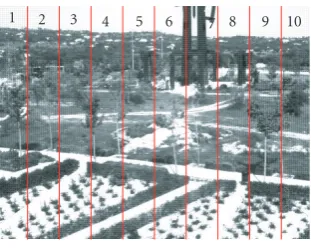
We have previously applied evaluation metrics to assess video surveillance systems [72]. In our evaluation system, each time a track is initiated or updated by the agent tracking plan, the results are stored for analysis by the evaluation sys-tem. To get a more detailed idea of system performance, the agent-camera plane is divided into 10 zones (seeFigure 9). Each zone is defined as a fixed number of pixels on thex -axis, 10% of the horizontal size of the image. The horizontal component has been selected to analyze the metrics because it is the main coordinate along which the objects move in this particular study.
The metrics that we have applied to both experiments are the following.
(a) Initialization: this is the number of frame in which the intruder is detected by the agent tracking plan.
(b) Absolute area error: this is computed by calculating the area of the detected track. It is important to measure the absolute area to get an idea of what the camera is really track-ing. For example, in this case, the lights of the room make the intruder look bigger than her real size due to the pro-jected shadow. Therefore, the uncoordinated cameras track not only the shape of the person but also her shadow. The coordination messages overcome this problem by adapting the track to the real size.
(c) Transversal error (d(P,r)): it is defined as the dis-tance between the center of the bounding rectangle (P) and the segment (r), which is considered as ground truth (see Figure 10).
(d) Interframe area variation: this metric is defined as the variation of area between the current update and the previ-ous update of the track under study. It is required to check that the previous track exists. Otherwise, the value of this metric is zero.
(e) Continuity faults: the continuity faults metric is only measured inside a gate defined by the user. This gate is chosen so as to represent the area in which no new tracks can appear or disappear, because the intruder has already turned up on the right side of the image. This metric checks whether or
Corridor agent Surveillance Tracking intr.
Warning
Querying intr. Tracking intr.
cfp
Query Inform
Room agent Intruder close
to door 1 Surveillance
Tracking intr. Intruder out of
the corridor
Informing intr. Informing intr.
Figure8
1 2 3 4 5 6 7 8 9 10
Figure9: Segmentation of each frame into ten zones for better mea-surement accuracy.
not a current track inside the gate existed before. If the track did not exist, it means that this track was lost by the agent tracking plan and recovered in a subsequent frame. This be-havior must be computed as a continuity fault. This continu-ity metric is a counter, where one unit is added every time a continuity fault occurs.
(f) Number of tracked objects: it is known that there is only one intruder per video, but the agent tracking plan may fail and sometimes follow more than one or zero. Thus, every time a track is initiated, the agent surveillance plan marks it with a unique identifier. This metric consists of a counter, which is increased by one unit every time a new object with a new identifier appears in the area under study. After the evaluation of all the videos, this metric is normalized by the total number.
5.1.3. Performance results
The following tables and graphs compare tracking system performance with and without the agent coordination op-erating in the system.
(0, 0)
d(P,r)= APxv
v
Zone 1 Zone 2 Zone 3 Zone 4 Zone 5 Zone 6
r
A v
d(P,r)
P x-axis
y
-axis
Figure10: Distance from a target to a reference path.
be removed. On the other hand, if the tracking system has no previous knowledge, the initialization will be carried out after the agent-camera surveillance plan detects the intruder. Second, the absolute area error of the tracked object with activated agent coordination is almost constant as is clear fromFigure 11(b), compared with the isolated case (a). We find that the area onFigure 11(b) has a much lower varia-tion and is almost constant compared with the situavaria-tion on Figure 11(a). The graphs in Figures 11and14have a solid line indicating the mean value, two dashed lines around the solid line representing standard deviation (+−1σ), and two dotted lines specifying the maximum and minimum values. The graphs are divided horizontally into 10 zones represent-ing the whole area covered by the agent surveillance plan.
The effect on the estimated area is because the corridor agent-camera sends stable information about the location and size of the intruder to the agent-camera in the room. This agent quickly initializes and rebuilds the representation, which is updated later from the observation generated by the actual camera. Thus, the surveillance system processes some blobs that are added to with the knowledge passed in the message: height and width of the person. Therefore, the surveillance system tracks the available blobs (some of which are impossible to detect due to occlusions) and reconstructs the original size. Furthermore, this computation stops shad-ows and reflections from being taken into account, because this spurious information tracked by the surveillance system will not fit in with the previous information and will be dis-carded.Figure 12shows the points marked as pixels in mo-tion. Many of these points are spurious information due to the light coming into the room when the door is opened and the reflection of this light on the wall. Furthermore, the in-truder is partially occluded by the tables and computers. The system is able to reconstruct the position and the size of the intruder and remove the incorrect information.
Obviously, the interframe area variation, or the variation of the area from the last to the current update of the track un-der study, of our new system is very low, since the room agent has information about the location and size of the intruder, and this is used for its estimations.
The following pictures give us a clear idea of system performance. Figures 13(a)and13(b) are two frames of a video sequence, Figures 13(c) and 13(d) show the points marked as pixels in motion, and Figures 13(e) and 13(f)
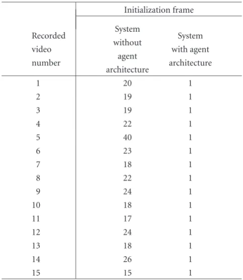
Table1: Comparison of the initialization of an intruder track for the two available systems. The system with agent architecture initial-izes the track when a message from the outside camera is received by the inside camera (frame number 1).
Initialization frame
Recorded System System
video without with agent
number agent architecture
architecture
1 20 1
2 19 1
3 19 1
4 22 1
5 40 1
6 23 1
7 18 1
8 22 1
9 24 1
10 18 1
11 17 1
12 24 1
13 18 1
14 26 1
15 15 1
contain the system output. Thus, Figure 13(c) shows the blobs processed by the system for Figure 13(a). The sys-tem cannot capture any more blobs of the intruder, as there are obstacles (tables and computers) in the way. The surveillance system outputs the intruder track that is de-picted in Figure 13(e) by the smaller rectangle. Neverthe-less, the coordinated agent rebuilds the intruder track us-ing the previous knowledge of the intruder’s size. The same process is shown for Figure 13(b). In this case, the obsta-cles allow the surveillance system to capture more pixels so that the system has to rebuild fewer parts of the in-truder.
The transversal error with respect to ground truth is de-picted for both cases inFigure 14. It is clear that the error is almost zero for the second architecture (Figure 14(b)) be-cause the track is adjusted using the previous knowledge. As we said before, the system takes the track output by the surveillance system and rebuilds it using the intruder’s char-acteristics. In both cases, the system considers the line de-fined by the centers of mass of the whole person as ground truth, that is, the centers of the reconstructed tracks from door 2 to door number 1.
1 2 3 4 5 6 7 8 9 10 0
0.5 1 1.5 2 2.5 10
4
(a)
1 2 3 4 5 6 7 8 9 10
0 2 4 6 8 10 12 14 16 18
10
3
(b)
Figure11: Absolute area error for the architecture without (a) and with (b) agent coordination.
Original track Ground truth line
Rebuilt track
Figure12: Reconstruction of the track based on previous knowledge.
Finally, in Figure 16, the number of tracked objects shows that the system with agent coordination stores a cor-rect representation (one intruder) in zones 8, 9, and 10, which are the areas close to door number 2, and makes a smooth transition to actual detections (from zone 7 to the left). This is because the system initializes the intruder track from the very beginning, while this initialization is de-layed considerably in the system without agent coordina-tion.
5.2. Outdoor scenario
We now describe the second scenario in which coordinated surveillance has been applied. There are two cameras aimed at a footpath and their goal is to detect and track pedestri-ans (they could also be considered intruders). Both cameras
share an area as depicted in Figure 17. The moment the pedestrian reaches the shared area, the right agent (camera 1) starts a“warning about expected object dialog”with the left agent (camera 2).
(a) (b)
(c) (d)
Original track Ground truth line
Rebuilt track
(e)
Ground truth line
(f)
Figure13: System performance.
1 2 3 4 5 6 7 8 9 10
0 5 10 15 20 25 30 35 40 45 50
(a)
1 2 3 4 5 6 7 8 9 10
10 0 10 20 30 40 50
(b)
Figure14: Transversal error for the architecture without (a) and with (b) agent coordination.
performance, the main advantage illustrated in this sce-nario is the possibility of extending the left agent’s func-tionality. In other words, by means of connection and dis-connection actions, the left agent can carry out the main task of surveillance and other activities, such as zoom or scanning of other areas. Obviously, this agent-governed setup of the visual network, in which the interaction of
cameras with human operator takes a lower priority than the performance of automatic surveillance tasks, can be switched to fully manual operation when the human ur-gently needs to have control of the cameras (e.g., in an emer-gency).
1 2 3 4 5 6 7 8 9 10 0
0.01 0.02 0.03 0.04 0.05 0.06 0.07
1 2 3 4 5 6 7 8 9 10
1 0.8 0.6 0.4 0.2 0 0.2 0.4 0.6 0.8 1
Figure15: Continuity faults for both architectures.
1 2 3 4 5 6 7 8 9 10
0 0.2 0.4 0.6 0.8 1 1.2 1.4
1 2 3 4 5 6 7 8 9 10
0 0.2 0.4 0.6 0.8 1 1.2 1.4
Figure16: Number of tracked objects.
some incorrect detection due to the movement of trees and plants and noise.
5.2.1. BDI representation
In this scenario, we also had to make several simplifications of the general problem. For instance, we assume the follow-ing.
(1) There are only two cameras with a shared area. (2) There are three moving objects, one of them in a
shared area, and one object for the exclusive field of view of each agent.
(3) One of the objects is moving from the field of view of one agent to the other.
Based on these assumptions and using our agent coor-dination framework, we particularize the beliefs for this sce-nario.
(1) The agents are close to each others.
(2) The shared area that links the field of view of one agent with the field of view of the respective agent.
(3) Location of the moving object with three possible val-ues: not-visible, shared area identifier, and exclusive-zone.
(4) Description of the moving object (coordinates of the center of gravity and trajectory).
These beliefs are enough to run an execution where there is a camera-agent (identified as “left”) located on the left side of the scenario that is tracking the move-ment of two objects (identified as “intruder0” and “in-truder1”), and there is another camera-agent (identified as “right”) located on the right side of the scenario (identi-fied as “right”) that is tracking the movement of one ob-ject (identified as “intruder2”) and there is an overlap with some of the field of view of the left agent (identified as “over-lap0”).
Shared area
Shared area
Camera-agent 1 Camera-agent 2
Figure17: Layout for scenario 2. There are two camera-agents sharing an overlapping zone labelled as “shared area.”
And the right agent is executing just one tracking plan for pedestrian2 and a surveillance plan. It has also these initial beliefs: “close-agent (left, overlap0)” and “location-pedestrian (“location-pedestrian2, exclusive-zone).”
When the left agent receives an external event (possi-bly caused by a human operator) requesting manual control of the left camera, it sends a query-if message to the right agent asking for permission and also a cfp message for object pedestrian1 to be tracked in advance by the right agent since it is located in the shared zone “overlap0.”
(query-if
:sender (agent left) :receiver (agent right) :content (is-anyone-coming?) :reply-with queryanyone )
(cfp
:sender (agent left) :receiver (agent right)
:content (track (pedestrian-at (pedestrian1, overlap0))) :reply-with cfpx
)
On the other hand, the right agent will answer the cfp message with the respective propose message to be accepted by the left agent with an accept-proposal message. Further-more, the query-if message will be answered by an inform message, letting the left agent know about pedestrian2 since this object is moving towards the left agent.
(inform
:sender (agent right) :receiver (agent left))
:content ((object pedestrian2))(mseg-expected 30) :in-reply-to queryanyone
:reply-with informcoming )
Finally, the left agent will make a decision (confirm/dis-confirm) on its temporary unavailability. For instance, a con-firm message including the information received about the
pedestrian that is moving towards it in the content attribute of the message. The dynamic schema of the “requesting for a break dialog ” is depicted inFigure 18.
(confirm
:sender (agent left) :receiver (agent right))
:content ((object pedestrian2))(mseg-expected 30) :in-reply-to informcoming
)
5.2.2. Experimental evaluations
For evaluation purposes, we consider that the pedestrians ap-pear on the right side of the scene, and move from right to left. As mentioned, both cameras have a common area in their field of view, which is called “shared area.” This com-mon area allows the two cameras to track the targets simul-taneously. This turns out to be very useful when the second camera is carrying out other task (i.e., focus on the face of an-other previous target to try to identify him/her), and it needs some extra time to go back to track the new pedestrian that camera 1 has indicated.
Once the right agent has detected a pedestrian, it calcu-lates its size, location, and velocity. Based on these data, the right agent computes the seconds that it will take the pedes-trian reach the shared area. This operation is very simple: a subtraction of the current pixel from the one in which the common area starts, divided by the velocity in pixels per second, where both the position (pixels) and the velocity (pixels per second) are estimated by the Kalman filter. Thus, this is the time that the left agent has to perform the other task before going back to its original position in order to track the pedestrian indicated by the right agent.
Left agent
Surveillance Tracking intr.0 Tracking intr.1
Warning intr.1
Querying anyone
Tracking intr.1
cfp
Query
Inform
Confirm
Inform
Right agent
Human asking for manual control
Surveillance Tracking intr.2
Tracking intr.1
Informing anyone about intr.2
Informing intr.1
Figure18
Table2: Mean velocity of pedestrians in videos.
Target ID Mean velocity (pixels/s)
1 −47.74535809
2 −43.02059497
3 −45.10638298
4 −49.1646778
5 −50.57208238
6 −47.84482759
7 −47.74590164
8 −49.6
9 −55.09138381
10 −72.04301075
11 −74.75728155
12 −128
13 −181.25
14 −215.2173913
Therefore, the faster the pedestrian moves, the less time the left agent has to carry out the other task, as is shown inFigure 19, which has been computed using the above for-mula.
To check the effect of the coordination between the two cameras, Figure 21shows what would happen if the infor-mation about the new pedestrian tracked by the right agent is not shared with the left agent.
To do this, we divided the left agent’s image into 10 equal zones, as we did in the evaluation of the previous scenario (Figure 20).
The experiment is composed of the following steps. First, the left agent is going to do another task and it will stop the surveillance activity without asking the right camera about nearby pedestrians. Therefore, the left camera will lose the field of view shown above to do a parallel action, that is, zoom in on a distant object. Then, while the left agent is
400 350 300 250 200 150 100 50 0 0
5 10 15 20 25
30 Time to go back to the original position for camera 2
Figure19: Seconds remaining for the left agent as a function of the velocity (pixels per second) of the target detected by the right agent.
1 2 3 4 5 6 7 8 9 10
Figure20
1 2 3 4 5 6 7 8 9 10 Zones of the image
0 0.2 0.4 0.6 0.8 1
P
robabilit
y
o
f
fi
nding
an
int
ru
der
in
ea
ch
of
the
zones
5 seconds after the appearance of the target 10 seconds after the appearance of the target 13 seconds after the appearance of the target Results with agent coordination
Figure21: Probability of detecting a pedestrian in any of the zones into which the digital image is divided.
Then, the pedestrian comes into the field of view where it should be covered by the left camera and is therefore not detected. The following graph shows the probability of de-tecting a track in each of the zones within the field of view, supposing the left camera returns to the surveillance posi-tion 5 (line with squares), 10 (line with circles), or 13 sec-onds (line with stars) after the pedestrian appeared in the scene. This probability depends of the mean velocity of each pedestrian. Moreover, the line marked with triangles shows the probability of detecting a track when the agent coordina-tion is used. We can check that no target is lost, whereas the maximum of probability of detection without coordination is 0.8. That means that from the 14 targets, at least two of them are fast enough for not being detected.
If we had used coordination between agents, the left agent would have asked for permission to carry out another activ-ity and disconnect surveillance. The right agent would have replied, reporting the time remaining for the pedestrian to appear. Therefore, the left agent would have returned to the surveillance position in time to track the pedestrian. Then, as we said before, the graph inFigure 21is the straight line with probability 1 in all the zones.
6. CONCLUSIONS
In this paper a multi-agent framework has been applied to the management of a surveillance system using a visual sen-sor network. We have described how the use of software agents allows more robust and decentralized system to be de-signed, where management is distributed between the dif-ferent camera-agents. The architecture of each agent and its level of reasoning have been presented, as well as the mechanism (agent dialogs) implemented for coordination.
Coordination enhances the continuous tracking of objects of interest within the covered areas, improves the knowledge in-ferred from information captured at different nodes, and ex-tends surveillance functionalities through an effective man-agement of network interdependences to carry out the tasks. These improvements have been shown with the frame-work operating in a surveillance space (indoor and outdoor configuration for a university campus) using several numeric performance metrics. The software agents’ ability to repre-sent real situations has been analyzed, as well as how the ex-changed information improves the coordination between the camera agents, thereby enhancing the overall performance and functionalities of the network.
ACKNOWLEDGMENTS
This work was funded by projects CICYT TSI2005-07344, CICYT TEC2005-07186, and CAM MADRINET S-0505/ TIC/0255.
REFERENCES
[1] Airport Surface Detection Equipment Model X (ASDE-X),
http://www.sensis.com/docs/128.
[2] M. E. Weber and M. L. Stone, “Low altitude wind shear de-tection using airport surveillance radars,”IEEE Aerospace and Electronic Systems Magazine, vol. 10, no. 6, pp. 3–9, 1995. [3] A. Pozzobon, G. Sciutto, and V. Recagno, “Security in ports:
the user requirements for surveillance system,” inAdvanced Video-Based Surveillance Systems, C. S. Regazzoni, G. Fabri, and G. Vernazza, Eds., Kluwer Academic, Boston, Mass, USA, 1998.
[4] P. Avis, “Surveillance and Canadian maritime domestic secu-rity,”Canadian Military Journal, vol. 4, no. 1, pp. 9–15, 2003. [5] B. P. L. Lo, J. Sun, and S. A. Velastin, “Fusing visual and
au-dio information in a distributed intelligent surveillance system for public transport systems,”Acta Automatica Sinica, vol. 29, no. 3, pp. 393–407, 2003.
[6] C. Nwagboso, “User focused surveillance systems integration for intelligent transport systems,” in Advanced Video-Based Surveillance Systems, C. S. Regazzoni, G. Fabri, and G. Ver-nazza, Eds., chapter 1.1, pp. 8–12, Kluwer Academic, Boston, Mass, USA, 1998.
[7] ADVISOR specification documents (internal classification 2001).
[8] http://dilnxsrv.king.ac.uk/cromatica/.
[9] N. Ronetti and C. Dambra, “Railway station surveillance: the Italian case,” inMultimedia Video Based Surveillance Systems, G. L. Foresti, P. Mahonen, and C. S. Regazzoni, Eds., pp. 13– 20, Kluwer Academic, Boston, Mass, USA, 2000.
[10] M. Pellegrini and P. Tonani, “Highway traffic monitoring,” in Advanced Video-Based Surveillance Systems, C. S. Regazzoni, G. Fabri, and G. Vernazza, Eds., Kluwer Academic, Boston, Mass, USA, 1998.
[11] D. Beymer, P. McLauchlan, B. Coifman, and J. Malik, “A real-time computer vision system for measuring traffic parame-ters,” inProceedings of the IEEE Computer Society Conference on Computer Vision and Pattern Recognition (CVPR ’97), pp. 495–502, San Juan, Puerto Rico, USA, June 1997.
[13] L. Jian-Guang, L. Qi-Feing, T. Tie-Niu, and H. Wei-Ming, “3-D model based visual traffic surveillance,”Acta Automatica Sinica, vol. 29, no. 3, pp. 434–449, 2003.
[14] J. M. Ferryman, S. J. Maybank, and A. D. Worrall, “Vi-sual surveillance for moving vehicles,”International Journal of Computer Vision, vol. 37, no. 2, pp. 187–197, 2000.
[15] http://www.detec.no. [16] http://www.gotchanow.com.
[17] http://secure30.softcomca.com/fge biz.
[18] T. Brodsky, R. Cohen, E. Cohen-Solal, et al., “Visual surveil-lance in retail stores and in the home,” in Advanced Video-based Surveillance Systems, chapter 4, pp. 50–61, Kluwer Aca-demic, Boston, Mass, USA, 2001.
[19] R. Cucchiara, C. Grana, A. Prati, G. Tardini, and R. Vez-zani, “Using computer vision techniques for dangerous situa-tion detecsitua-tion in domotic applicasitua-tions,” inProceedings of the IEE Workshop on Intelligent Distributed Surveillance Systems (IDSS ’04), pp. 1–5, London, UK, February 2004.
[20] D. Greenhill, P. Remagnino, and G. A. Jones, “VIGILANT: content querying of video surveillance streams,” in Video-Based Surveillance Systems, P. Remagnino, G. A. Jones, N. Paragios, and C. S. Regazzoni, Eds., pp. 193–205, Kluwer Aca-demic, Boston, Mass, USA, 2002.
[21] C. Micheloni, G. L. Foresti, and L. Snidaro, “A co-operative multicamera system for video-surveillance of parking lots,” inProceedings of the IEE Workshop on Intelligent Distributed Surveillance Systems (IDSS ’03), pp. 21–24, London, UK, February 2003.
[22] T. E. Boult, R. J. Micheals, X. Gao, and M. Eckmann, “Into the woods: visual surveillance of noncooperative and camouflaged targets in complex outdoor settings,”Proceedings of the IEEE, vol. 89, no. 10, pp. 1382–1401, 2001.
[23] M. Xu, L. Lowey, and J. Orwell, “Architecture and algorithms for tracking football players with multiple cameras,” in Pro-ceedings of the IEE Workshop on Intelligent Distributed Surveil-lance Systems (IDSS ’04), pp. 51–56, London, UK, February 2004.
[24] J. Krumm, S. Harris, B. Meyers, B. Brumit, M. Hale, and S. Shafer, “Multi-camera multi-person tracking for easy living,” inProceedings of 3rd IEEE International Workshop on Visual Surveillance (VS ’00), pp. 3–10, Dublin, Ireland, July 2000. [25] J. Heikkil¨a and O. Silv´en, “A real-time system for monitoring
of cyclists and pedestrians,” inProceedings of 2nd IEEE Inter-national Workshop on Visual Surveillance (VS ’99), pp. 74–81, Fort Collins, Colo, USA, 1999.
[26] I. Haritaoglu, D. Harwood, and L. S. Davis, “W4: real-time surveillance of people and their activities,”IEEE Transactions on Pattern Analysis and Machine Intelligence, vol. 22, no. 8, pp. 809–830, 2000.
[27] http://www.cieffe.com. [28] http://www.objectvideo.com. [29] http://www.nice.com. [30] http://www.pi-vision.com. [31] http://www.ipsotek.com. [32] http://www.neurodynamics.com.
[33] I. Haritaoglu, D. Harwood, and L. S. Davis, “Hydra: multiple people detection and tracking using silhouettes,” in Proceed-ings of 2nd IEEE Workshop on Visual Surveillance (VS ’99), pp. 6–13, Fort Collins, Colo, USA, July 1999.
[34] J. Batista, P. Peixoto, and H. Araujo, “Real-time active visual surveillance by integrating peripheral motion detection with foveated tracking,” inProceedings of the IEEE Workshop on Vi-sual Surveillance (VS ’98), pp. 18–25, Bombay, India, January 1998.
[35] Y. Ivanov, A. Bobick, and J. Liu, “Fast lighting independent background subtraction,” International Journal of Computer Vision, vol. 37, no. 2, pp. 199–207, 2000.
[36] R. Pless, T. Brodsky, and Y. Aloimonos, “Detecting inde-pendent motion: the statistics of temporal continuity,”IEEE Transactions on Pattern Analysis and Machine Intelligence, vol. 22, no. 8, pp. 768–773, 2000.
[37] L.-C. Liu, J.-C. Chien, H. Y.-H. Chuang, and C. C. Li, “A frame-level FSBM motion estimation architecture with large search range,” inProceedings of the IEEE Conference on Ad-vanced Video and Signal Based Surveillance (AVSS ’03), pp. 327–333, Miami, Fla, USA, July 2003.
[38] P. Remagnino, A. Baumberg, T. Grove, et al., “An integrated traffic and pedestrian model-based vision system,” in Proceed-ings of the British Machine Vision Conference (BMVC ’97), pp. 380–389, Essex, UK, 1997.
[39] K. C. Ng, H. Ishiguro, M. Trivedi, and T. Sogo, “Monitoring dynamically changing environments by ubiquitous vision sys-tem,” inProceedings of 2nd IEEE Workshop on Visual Surveil-lance (VS ’99), pp. 67–74, Fort Collins, Colo, USA, July 1999. [40] J. Orwell, P. Remagnino, and G. A. Jones, “Multi-camera
colour tracking,” inProceedings of the 2nd IEEE Workshop on Visual Surveillance (VS ’99), pp. 14–21, Fort Collins, Colo, USA, July 1999.
[41] T. Darrell, G. Gordon, J. Woodfill, H. Baker, and M. Harville, “Robust real-time people tracking in open environments us-ing integrated stereo, color, and face detection,” inProceedings of the 3rd IEEE Workshop on Visual Surveillance (VS ’98), pp. 26–33, Bombay, India, January 1998.
[42] N. Rota and M. Thonnat, “Video sequence interpretation for visual surveillance,” inProceedings of 3rd IEEE International Workshop on Visual Surveillance (VS ’00), pp. 59–68, Dublin, Ireland, July 2000.
[43] J. Owens and A. Hunter, “Application of the self-organising map to trajectory classification,” inProceedings of 3rd IEEE In-ternational Workshop on Visual Surveillance (VS ’00), pp. 77– 83, Dublin, Ireland, July 2000.
[44] C. Stauffer and W. E. L. Grimson, “Learning patterns of ac-tivity using real-time tracking,”IEEE Transactions on Pattern Analysis and Machine Intelligence, vol. 22, no. 8, pp. 747–757, 2000.
[45] E. Stringa and C. S. Regazzoni, “Content-based retrieval and real time detection from video sequences acquired by surveil-lance systems,” inProceedings of the IEEE International Con-ference on Image Processing (ICIP ’98), vol. 3, pp. 138–142, Chicago, Ill, USA, October 1998.
[46] C. Decleir, M.-S. Hacid, and J. Koulourndijan, “A database ap-proach for modeling and querying video data,” in Proceed-ings of the 15th International Conference on Data Engineering (ICDE ’99), pp. 1–22, Sydney, Australia, March 1999. [47] D. Makris, T. Ellis, and J. Black, “Bridging the gaps between
cameras,” inProceedings of the IEEE Computer Society Confer-ence on Computer Vision and Pattern Recognition (CVPR ’04), vol. 2, pp. 205–210, Washington, DC, USA, June-July 2004. [48] J. Black, T. Ellis, and P. Rosin, “A novel method for video
track-ing performance evaluation,” in Proceedings of the IEEE In-ternational Workshop on Visual Surveillance and Performance Evaluation of Tracking and Surveillance, pp. 125–132, Nice, France, October 2003.
[49] M. Valera and S. A. Velastin, “Intelligent distributed surveil-lance systems: a review,”IEE Proceedings: Vision, Image and Signal Processing, vol. 152, no. 2, pp. 192–204, 2005.