Volume 2008, Article ID 286168,10pages doi:10.1155/2008/286168
Research Article
Extension of Pairwise Broadcast Clock Synchronization for
Multicluster Sensor Networks
Kyoung-Lae Noh,1Yik-Chung Wu,2Khalid Qaraqe,3and Bruce W. Suter4
1Digital Solution Center, Corporate Technology Operations, Samsung Electronics Co., Ltd., South Korea 2Department of Electrical and Electronic Engineering, The University of Hong Kong, Hong Kong 3Texas A&M University at Qatar, P.O. Box 23874, Doha, Qatar
4Information Directorate, Air Force Research Laboratory/RITC, Rome, NY 13441, USA
Correspondence should be addressed to Yik-Chung Wu,[email protected]
Received 26 April 2007; Revised 28 September 2007; Accepted 15 November 2007
Recommended by Paul Cotae
Time synchronization is crucial for wireless sensor networks (WSNs) in performing a number of fundamental operations such as data coordination, power management, security, and localization. The Pairwise Broadcast Synchronization (PBS) protocol was recently proposed to minimize the number of timing messages required for global network synchronization, which enables the design of highly energy-efficient WSNs. However, PBS requires all nodes in the network to lie within the communication ranges of two leader nodes, a condition which might not be available in some applications. This paper proposes an extension of PBS to the more general class of sensor networks. Based on the hierarchical structure of the network, an energy-efficient pair selection algorithm is proposed to select the best pairwise synchronization sequence to reduce the overall energy consumption. It is shown that in a multicluster networking environment, PBS requires a far less number of timing messages than other well-known syn-chronization protocols and incurs no loss in synsyn-chronization accuracy. Moreover, the proposed scheme presents significant energy savings for densely deployed WSNs.
Copyright © 2008 Kyoung-Lae Noh et al. This is an open access article distributed under the Creative Commons Attribution License, which permits unrestricted use, distribution, and reproduction in any medium, provided the original work is properly cited.
1. INTRODUCTION
Recently, a huge attention has been paid to wireless sen-sor networks (WSNs) as fundamental infrastructures for
fu-ture ubiquitous communication environments [1,2]. With
the help of current technical developments in microelec-tromechanical systems (MEMS) and wireless communica-tions, the feasibility of WSNs keeps rapidly growing. Time (clock) synchronization is a procedure for providing a com-mon notion of time across a distributed system. Hence, it is essential to maintain data consistency and
coordina-tion, and to perform other fundamental operations [2–4].
The Network Time Protocol (NTP) [5] is the most
popu-lar synchronization protocol for distributed networks due to its diverse advantages in the Internet environment. How-ever, NTP is subject to a number of critical issues when applied to WSNs because of the unique nature of sensor networks: limited power resources, adverse wireless chan-nel conditions, and dynamic topology changes. For this
reason, different types of synchronization schemes have
been developed thus far for sensor network applications [2].
The Reference-Broadcast Synchronization (RBS) proto-col was proposed to synchronize a group of wireless sen-sors within the transmission range of the reference sensor
node, which alleviates the effects of random delays in
tim-ing message delivery [6]. Using a similar approach to NTP,
the Timing-sync Protocol for Sensor Networks (TPSN) was
proposed in [7]. TPSN is based on the level hierarchy of the
network, and synchronizes the entire network by exchanging timing messages along every branch (edge) of the hierarchi-cal tree. For synchronization protocols based on the two-way
message exchanges like TPSN, a family of energy-efficient
clock offset and skew (frequency offset) estimators was
re-cently proposed in [8].
More recently, the Flooding Time Synchronization
Pro-tocol (FTSP) [9] synchronizes the network by successively
broadcasting the synchronization messages using MAC layer time-stamping and performing skew compensation based on
Receive-only synchronization Region of pairwise sync.
(NodesPandA) Sender-receiver synchronization (2-way message exchanges)
Leader nodes B
A P
Figure1: Pairwise broadcast synchronization for a single-cluster network.
proposed in [10]. TDP selects a set of the diffusion
lead-ers in every level of the network considering the balance of workload and the stability of the local clocks. Considering
uniformly distributed quantization noise,Sadlerderived the
joint maximum likelihood clock offset and skew estimators,
and also proposed a detection mechanism of clock drift [11].
GiridharandKumarproposed a distributed clock nization algorithm to improve the accuracy level of synchro-nization under the condition that every connected edge
ex-changes timing messages [12]. Besides, several time
synchro-nization protocols based on the beacon transmission at the physical layer have been reported as well. Assuming a realis-tic wireless channel environment, a distributed broadcasting
time synchronization scheme was proposed byKhajehnouri
and Sayedto overcome the effects of multipath frequency
selective fading in [13]. A low-complexity bio-inspired
syn-chronization protocol for large scale WSNs was reported by
HongandScaglionein [14].
The tradeoffbetween the accuracy and energy
consump-tion (complexity) is the most important and crucial factor in designing time synchronization protocols for WSNs due to the space and power limitations of sensor nodes. Indeed, more energy consumption is required in general to increase the synchronization accuracy. Hence, the energy consump-tion for synchronizaconsump-tion should be kept as small as possible while satisfying a certain accuracy level. The Pairwise Broad-cast Synchronization (PBS) protocol was recently proposed with the aim of minimizing the overall energy consump-tion for achieving global network synchronizaconsump-tion without incurring any loss in synchronization accuracy relative to
the existing protocols [15]. PBS is based on the idea that
while two nodes performing synchronization using two-way message exchanges, other nodes lying nearby can overhear
the messages and can also synchronize themselves. PBS effi
-ciently combines the merits of two different basic
nization approaches, namely, the sender-receiver synchro-nization (SRS) and the receiver-only synchrosynchro-nization (ROS) approaches, to achieve global synchronization with a signif-icantly reduced number of synchronization messages, that is, with reduced energy consumption. However, the original
form of PBS assumes that every node in the network should be located within the communication ranges of the leader nodes. That is, PBS is mainly designed for single-cluster
sen-sor networks, and hence, its efficient extension to general
multicluster-based sensor networks represents an interesting open research problem. This paper studies a multicluster ex-tension of PBS based on the level hierarchy of the network
and proposes an energy efficient pair selection algorithm to
achieve global synchronization.
The rest of this paper is organized as follows. InSection 2,
we overview the key features of PBS and illustrate the way to achieve networkwide synchronization for single-cluster sensor networks. For the extension to general
multiclus-ter sensor networks, Section 3 proposes the networkwide
pair selection algorithm and the groupwise pair selection algorithm to select the best synchronization sequence aim-ing at minimizaim-ing the overall energy consumption.
Be-sides, Section 3 presents simulation results on the
perfor-mance of the proposed pair selection algorithms with re-spect to the number of required synchronization messages
(i.e., energy consumption). Finally, Section 4 summarizes
and concludes this paper.
2. SYNCHRONIZATION FOR SINGLE-CLUSTER
NETWORKS USING PAIRWISE BROADCAST SYNCHRONIZATION
Suppose there are two leader nodes (Nodes PandA) in the
network, and every node in the network is located within the communication ranges of these leader nodes as depicted in Figure 1. Note that the leader nodes are just ordinary nodes like other sensor nodes in the network. Here, the net-work consists of a single cluster, and the two leader nodes perform a pairwise synchronization using two-way timing message exchanges, which has been thoroughly analyzed in
[8,17,18]. Note that all the nodes in the common coverage
(checked) region can receive a series of synchronization mes-sages containing information about the time stamps of the pairwise synchronization. Using this information, any node
applying the ROS approach with no additional timing
mes-sage transmissions [15]. Here,Nodes PandAprovide
syn-chronization beacons for all the nodes located in their vicin-ity.
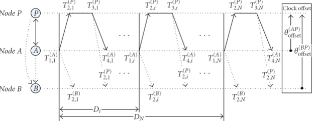
More specifically, the clock model for PBS is described inFigure 2, whereθ(oAPffset) stands for the clock offset between Nodes AandP, andθ(oBPffset) is the clock offset betweenNodes B
andP. In order to synchronizeNodes AandP,Node A
trans-mits a synchronization packet toNode P, which contains the
level and identifier (ID) ofNode A and the values of time
stampT1,(Ai).Node Preceives it atT (P)
2,i and transmits an
ac-knowledgment packet toNode AatT3,(Pi). This packet contains
the level and ID ofNode Pand the values of time stampsT1,(Ai),
T2,(Pi), andT (P)
3,i . Finally,Node Areceives the acknowledgment
packet atT4,(Ai). The above timing messages exchange
proce-dure is performed multiple (N) times, and the clock offset
and skew betweenNodes PandAcan be estimated based on
T1,(Ai),T (P) 2,i ,T
(P) 3,i, andT
(A) 4,i [8].
Now, consider an arbitrary node, sayNode B, inFigure 1.
WhileNodes PandA are exchanging time messages, Node
Bis capable of receiving packets from both nodes. AtNode
B, when it receives packets fromNode A, it records the
ar-rival time as{T2,(Bi)}Ni=1, as shown inFigure 2. Similarly, when Node B receives packets from Node P, the arrival time is recorded as{T2,(Pi)}Ni=1. Besides,Node Bcan also get the time
readings{T1,(Ai)}Ni=1since it is embedded in the packets from Node A. Based on the time readings{T1,(Ai)}Ni=1,{T
(B)
2,i }Ni=1, and {T2,(Pi)}Ni=1inNode B, the joint clock offset and skew estimator
using the ROS approach is given by [15]
⎡ ⎢ ⎣θ
(BP) offset
θ(skewBP)
⎤ ⎥
⎦= 1
N Ni=1Di2− Ni=1Di
2 × ⎡ ⎢ ⎢ ⎢ ⎢ ⎢ ⎣ N
i=1
D2 i
N
i=1
x[i]− N
i=1
Di N
i=1
Di·x[i]
N N
i=1
Di·x[i]− N
i=1
Di N
i=1
x[i] ⎤ ⎥ ⎥ ⎥ ⎥ ⎥ ⎦, (1)
whereDiT1,(Ai)−T (A)
1,1 andx[i]T (P) 2,i −T
(B)
2,i . Consequently,
Node Bcan be synchronized toNode Pusing the results in
(1), and all the other nodes in the common coverage region
inFigure 1can also be simultaneously synchronized toNode
Pwithout any additional timing message transmissions, thus
saving a significant amount of energy. Note that it was shown
in [15] that the synchronization accuracy of PBS is exactly
the same as the RBS protocol.
For a network with L sensor nodes, let NTPSN, NFTSP,
andNRBS denote the numbers of required timing messages
in network synchronization using TPSN, FTSP, and RBS,
re-spectively. It has been proven [16] thatNTPSN=2N(L−1),
NFTSP = NL, andNRBS = N+L(L−1)/2, whereN is the number of times synchronization messages are transmitted or exchanged when synchronizing two nodes.
It is remarkable that the required number of timing mes-sages for all the above-mentioned protocols is proportional
to the number of sensors in the networkLor its squareL2.
On the other hand, since PBS adopts the energy efficient ROS
approach, it can synchronize a set of nodes based on the mes-sages exchanged between the two leader nodes. Thus PBS
re-quires only 2Ntiming messages during each synchronization
period (i.e.,NPBS =2N). Hence,NPBSdoes not depend on
the number of sensors in the network, a fact which incurs an enormous amount of energy saving. Moreover, this gain increases proportionally with respect to the scale of the net-work. Consequently, the benefit of PBS over RBS, TPSN, and FTSP is clear and huge in terms of energy consumption.
3. SYNCHRONIZATION FOR MULTICLUSTER
NETWORKS
In the previous section, we only concentrated on the case where all the nodes lie within a single cluster. For example, inFigure 1, all the nodes are located inside the checked re-gion. In this section, we will present the extension of PBS to networks which consist of more than one cluster.
In a multicluster network, there are two possible sce-narios for extending the proposed PBS. When there is no problem with the deployment of leader nodes in the right positions of the network, the whole sensor field can be di-vided into several clusters, where each cluster contains two individual leader nodes whose communication ranges cover the entire cluster. Hence, every cluster can be first synchro-nized by performing a pairwise synchronization between the pair of leader nodes and other nodes within the cluster per-forming ROS. Then, like RBS, global synchronization can be achieved by additional message exchanges (based on SRS)
among leader nodes in different clusters. In this case, the
ex-tension of PBS becomes mostly the problem of network im-plementation just like cell-planing problems in mobile com-munication networks.
However, if deploying leader nodes in a planned fash-ion is not possible, then there is no way to apply the above-mentioned procedure. For this general scenario, we have to choose which nodes perform pairwise synchronization and which nodes perform ROS. For the rest of the paper, we fo-cus on this scenario since it represents a more general
situa-tion. Considering the energy-efficiency requirement in time
synchronization, the question becomes how to select the op-timum set of nodes that performs pairwise synchronizations such that all other nodes in the network can be synchronized using ROS?
In this paper, we propose an energy-efficient pair
selec-tion algorithm, named the groupwise pair selecselec-tion algo-rithm (GPA), to achieve global synchronization using ROS. In the following, we first show a way to achieve global syn-chronization based on the networkwide heuristic search in order to reveal some preliminary ideas on pair selection problem. Then, the proposed GPA is presented in detail.
3.1. Networkwide pair selection algorithm
Considering the energy efficiency in time synchronization,
P
A
B
NodeP
NodeA
NodeB
T2,1(P)
T1,1(A)
T2,1(B)
T3,1(P)
T4,1(A)
T2,1(P) · · ·
T1,(Ai)
· · ·
T(2,Pi)
T2,(Bi)
T3,(Pi)
T4,(Ai) T1,(AN)
T2,(Pi) · · ·
· · ·
T2,(PN) T3,(PN)
T4,(AN)
T2,(PN)
T(2,BN)
θo(BPffset) θ(oAPffset)
Clock offset
Di
DN
Figure2: Clock synchronization model of PBS.
overall pairwise synchronizations in the network. There are two fundamental criteria to select the best synchronization pairs as follows:
(1) a pair of nodes containing the maximum number of nodes in their common coverage region of the pairwise synchronization has to be chosen during each selection step of the synchronization pair;
(2) a pair of nodes in the same level should not be selected as a valid pair in order to limit the bound for the max-imum synchronization error which increases with the number of levels of synchronization.
Therefore, to find the best synchronization pairs, informa-tion about the network hierarchy and connectivity, which can be obtained by beacon exchanges among nodes, is re-quired. This can be accomplished by applying the
well-known breath-first search algorithm [21], in which every
node in the network is required to send messages with their maximum power satisfying a certain energy constraint.
For a graphical illustration of the proposed algorithms,
Figure 3 shows an example of a network connection hier-archy. The pairwise synchronization begins with the
refer-ence nodeNode 1, and four different branches (edges) are
connected to the reference, that is, there are four different
nodes which can be chosen as the first synchronization pair. As mentioned before, the criterion for selecting the best pair is to find a pair of nodes maximizing the number of synchro-nizing nodes (based on the ROS approach) from the pairwise
synchronization. Letpi,jdenote the pairwise synchronization
betweenNodes iandj, and letprepresent the pairwise
syn-chronization sequence vector whose elements are a set ofpi,j.
Define also, by NROSi,j , the number of synchronizing nodes,
which are performing ROS from pi,j. In Figure 3, Node 4
must be selected as the first pair node sinceNROS1,4 =3, and it
represents the maximum achievable value among all possible
choices (all the other nodes in level 1,Nodes2, 3, and 5, can
be synchronized from p1,4). The same criterion can be
ap-plied to determine the next pair of nodes thereafter, until all
the nodes in the network are synchronized. Therefore, p3,8,
p4,11, andp11,14are chosen as the second, third, and fourth
pairs, respectively. Consequently, a sequence of pairwise syn-chronizations is chosen to maximize the number of nodes performing ROS. In this example, the pairwise synchroniza-tion sequence vector is given byp= {p1,4,p3,8,p4,11,p11,14}.
6 3 12
11
14 13 4 10
9 8 7
2
2
4
3
5
1
1
Level 1 Level 2
Level 3
Pairwise synchronization
Figure3: Network connection hierarchy for networkwide pair se-lection algorithm.
Now, we formally present the Networkwide Pair Selec-tion Algorithm (NPA) to find the pairwise synchronizaSelec-tion
sequence. A network can be represented as a graph G =
(V,E), whereVrepresents the set of nodes (e.g., inFigure 3,
V = {si}14
i=1) andEstands for the set of edges (branches),
whose elements are 2-element subsets ofV. AssumeLi
de-notes the subset of nodes located on leveli(e.g.,L0 = {s1},
L1= {si}5i=2,L2= {si}12i=6, andL3= {s13,s14}for the example
depicted byFigure 3). LetSdenote the set of synchronized
nodes whose initial element isS= {s1}, and letMi,j denote
theith row and jth column element of the adjacency matrix
M of the graphG, whereMi,j = 1 whenNodes iandjare
connected, andMi,j=0 otherwise.
Note that an arbitrary nodeNode kcan be synchronized
frompi,jif and only ifNodes iandjare connected andNode
kis connected to bothNodes iandj, that is,Mi,j =Mi,k =
Mj,k =1. Besides, the levels of the nodes in a
synchroniza-tion pair must differ by one. Therefore, the number of
syn-chronizing nodes fromp1,i(NROS1,i ) is given by
NROS1,i =
j=i
Hence, the first node to perform pairwise synchronization
withs1can be obtained by maximizingNROS1,i as follows:
i=arg max
i N
1,i
ROS, (3)
where si ∈ L1, otherwise, no connection exists between
Nodes 1 and i. In the example of Figure 3, i = 4 because
NROS1,4 =3 and achieves the maximum value (note that if there
are multiple candidates that maximizeNROS1,i , the algorithm
chooses randomly among these candidates). Thus,p1,4is
se-lected as the first pair. Note that because of the second selec-tion criterion menselec-tioned above, in general, to find the
sec-ond pair of nodes in this example, another node inL1should
be chosen until all the nodes inL1 are synchronized.
How-ever, in this example, there are no remaining unsynchronized
nodes inL1afterp1,4since all the nodes inL1are already
syn-chronized by p1,4 (i.e.,S = {L0,L1}after the first pairwise
synchronization).
The same maximization procedure can be applied to find the next synchronization pair. A general formula for finding
NROSi,j is given by
NROSi,j =
k=j
Mi,j·Mi,k·Mj,k ∀si∈S,sj,sk∈S, (4)
wheresiis a candidate of the next parent node and the levels
ofsj andsk are different from those of the parent node by
one in accordance with the second selection criterion. The
next synchronization pair can be found by maximizingNROSi,j
as follows:
(i,j)=arg max
i,j N
i,j
ROS. (5)
Here, pi,j becomes the next element ofp and all
synchro-nized nodes from pi,j are added to S. From (4) and (5),
the second synchronization pair becomes p3,8 in this
ex-ample since NROS3,8 =4 and is maximum among all possible
combinations ofi and j. Thus,p becomes{p1,4,p3,8} and
S= {L0,L1,{si}9i=6}. Likewise, the third pair is chosen to be p4,11,p = {p1,4,p3,8,p4,11}, andS= {L0,L1,L2}. Repeating
the same procedure (withsi∈L2) yieldsp11,14as the last
syn-chronization pair, and hence, a complete sequence becomes p= {p1,4,p3,8,p4,11,p11,14}as depicted inFigure 3.Figure 4
summarizes the NPA.
3.2. Groupwise pair selection algorithm
To discover the overall network connectivity, every single node in the network has to transmit the connection discov-ery beacons and send back acknowledgment packets upon receiving other beacons from its adjacent nodes (e.g., the
breath-first search algorithm in [21]). For WSNs consisting
of a large number of nodes, discovering the network con-nectivity is not a simple task and requires a huge number
of packet exchanges. Therefore, we propose an efficient
al-ternative method, the Groupwise Pair Selection Algorithm (GPA), which relies on the hierarchical structure (spanning tree) of the network to simplify the connection discovery procedure.
Input: Graph (G), Adjacency matrix (M), Maximum level/depth (dmax)
Output: PS sequence vector (p)
Initial values:n=m=1,S= {s1} 1 whilen≤dmax−1do
2 while∃sj∈Lnandsj∈Sdo
3 for alli,j, andkwith
si∈S,si∈Ln−1,{sj,sk} ∈S, and{sj,sk} ∈Ln
4 NROSi,j ← k=jMi,j·Mi,k·Mj,k
5 (i,j)←arg maxi,jN i,j
ROS.
6 p(m)←pi,j
7 m←m+ 1
8 All synchronized nodes frompi,jare added toS
9 end while
10 n←n+ 1 11 end while
∗p(m):mth element ofp
Figure4: Networkwide pair selection algorithm.
Note that the hierarchical tree of the network can be
gen-erated by a level discovery procedure as discussed in [7].
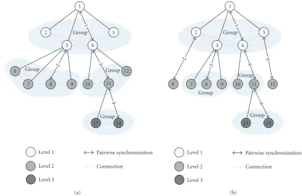
Once a hierarchical tree is established, there exist groups of nodes, where a group consists of a parent and its children
nodes, for example, inFigure 5(a), Nodes1, 2, 3, 4, and 5
form a group withNode1 being the parent and other nodes
being children. Similarly, another example isNodes3, 6, 7, 8,
and 9 form another group withNode3 being the parent node
and other nodes being the children nodes. Two additional
groups in this example areNodes4, 10, 11, 12 andNodes11,
13, 14, respectively.
In GPA, instead of discovering the entire network con-nectivity, every parent node only investigates the connectiv-ity among its children nodes (detailed procedure is to be pre-sented in the next section). Therefore, the reference node does not need to find the pairwise synchronization sequence of the entire network, but only needs to find the pairwise syn-chronization sequence among its children, and the other par-ent nodes successively perform the same connection search-ing procedure as the reference node. As a result, GPA signif-icantly reduces the complexity of building up a connection hierarchy, and requires a far smaller number of connection discovery beacons than NPA due to its limited set of scan-ning nodes.
Once the hierarchy of the whole network and the con-nectivity within every group of nodes have been established, the children nodes in each group synchronize with the parent node using either pairwise synchronization or ROS. In other words, the problem of synchronizing the whole network re-duces to synchronizing a number of individual groups, where each group consists of a parent and a number of children. In order to minimize the total number of synchronization mes-sages for the whole network, it is equivalent to minimizing the number of timing message exchanges in each group.
For each groupi, assume the parent node isNode i.
3
11 12 10
9 8 6
7
Group Group
Group Group
2
2
4
3
5
1
1
4
14 13
Level 1 Level 2 Level 3
Pairwise synchronization Connection
(a)
3
11 12
10 9 8
6 7
Group
Group
Group Group
2
3
2 5
4
4
5
1
1
6
14 13
Level 1 Level 2 Level 3
Pairwise synchronization Connection
(b)
Figure5: Examples of hierarchical spanning trees for groupwise pair selection algorithm.
for groupiand letSidenote the set of synchronized nodes
in groupiwith the initial elementSi = {si}. The number of
synchronizing nodes frompi,jis given by
NROSi,j =
k=j
Mj,k ∀sj,sk∈Si. (6)
In order to minimize the number of message exchanges in
groupi, the first child node chosen for pairwise
synchroniza-tion with its parent should be
j=arg max
j N
i,j
ROS. (7)
In this way, the maximum number of children nodes can be synchronized using ROS. After that, all synchronized nodes
from pi,j are added to Si, and pi,j is added to pi. If there
is any node in group i left unsynchronized, (6) and (7)
are repeated until all nodes are synchronized. In the
ex-ample of Figure 5(a), Nodes 4, 8, 11, and 14 are chosen
to perform pairwise synchronization with their respective
parents. The proposed GPA for group i is summarized in
Figure 6.
It is obvious that in GPA, the workload for finding the best pairwise synchronization sequence is shared among the reference node and the other parent nodes, that is, no net-workwide heuristic connectivity search is required for GPA.
Notice that in the example ofFigure 5(a), the network
syn-chronized using GPA requires the same number of pairwise synchronizations as that of NPA. However, the number of pairwise synchronizations for GPA depends on the specific
hierarchical tree, which is randomly constructed, and in gen-eral, is greater than that of NPA. For instance, for another
possible tree of the network as inFigure 5(b), the required
number of pairwise synchronizations is 6 instead of 4. Al-though it is true that, in general, GPA requires additional synchronization messages relative to NPA; in the next
sec-tion, we will show by simulations that this difference is very
small. On the other hand, the savings in complexity for estab-lishing the network hierarchy in GPA significantly outweighs the slight increase in terms of the number of synchronization messages, when compared to NPA. Next, we will present the connection discovery process for GPA.
3.2.1. Groupwise connection discovery
As the level discovery phase in TPSN [7], GPA first creates a
hierarchical structure (spanning tree) of the network, then it searches the connection status among a set of children nodes in every parent-children group. The connection discovery procedure in GPA consists of the following steps:
(1) select a reference node using an appropriate leader election algorithm (or picks up a node having the highest priority) and assign it to level zero;
(2) the reference node broadcasts a level discovery packet containing the identity and the level of packet; (3) every node who receives a level discovery packet
Input: The connectivity informationMj,kfor allsj,skwithin groupi Output: PS sequence vector (pi) of groupi
Initial value:m=1,Si= {si}wheresiis the parent node of groupi
1 while∃sj∈ groupiandsj∈Sido
2 for alljandks.t.{sj,sk} ∈ groupi, and{sj,sk} ∈Si
3 NROSi,j ← k=jMj,k
4 j← arg maxjNROSi,j .
5 pi(m)←pi,j
6 m←m+ 1
7 All synchronized nodes frompi,jare added toSi
8 end while
∗pi(m):mth element ofpi
Figure6: Groupwise pair selection algorithm for each groupi.
(4) repeat (5) until every node in the network is
success-fully assigned a level;
(5) once a hierarchical tree is established, every parent-children group performs the following operations: every child node broadcasts a connection discovery packet to other children nodes and sends back ac-knowledgment packets upon receiving other connec-tion discovery packets; connecconnec-tion discovery packets from any child node belonging to other groups will be discarded.
Notice that other algorithms (e.g., [22,23]) can also be
con-sidered when constructing the spanning tree (i.e., steps (1)– (4) above).
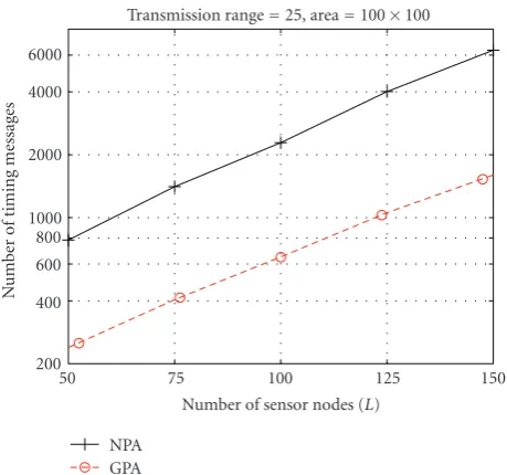
Figure 7compares the complexity of NPA in establish-ing the network connection hierarchy with that of GPA, which assumes a level hierarchy, with respect to the num-ber of sensor nodes. In this simulation, sensors are
ran-domly deployed in the area 100×100, the transmission
range of each sensor is set to be 25, and the reference node is assumed to be located at the center of the simulation area. 100.000 network topologies are generated and the av-erage complexity result is presented. It can be seen that the complexity becomes greater as the number of sensor nodes (equivalently the density) increases. The number of re-quired discovery messages for NPA is about four times larger than that of GPA. The following section analyzes the pro-posed algorithms in terms of the number of synchroniza-tion timing messages, and compares them with the existing protocols.
Remark 1. In this paper, we do not consider mobile sen-sor networks, but fixed sensen-sor networks. Therefore, recon-struction of network hierarchy is not (or rarely) required after the initial connection discovery. Moreover, according
to the simulation results in Figures 7 and 8 (to be
pre-sented in the next section), the required number of mes-sages for discovering network hierarchy in GPA is compa-rable to that of only a single synchronization round. Con-sequently, the overhead of constructing network hierarchy is not significant and negligible for fixed sensor network applications.
50 75 100 125 150
Number of sensor nodes (L) 200
400 600 800 1000 2000 4000 6000
N
u
mber
of
timing
messages
Transmission range=25, area=100×100
NPA GPA
Figure7: Number of messages for constructing the network hier-archy (GPA versus NPA).
3.3. Comparisons and analysis
This section compares the proposed algorithms with other conventional protocols such as TPSN, RBS, and FTSP in terms of the number of required synchronization timing messages in order to predict the energy required for
network-wide synchronization. Assume that|p|denotes the number
of elements in a pairwise synchronization sequence vectorp,
then the total number of timing messages for NPA (NNPA) is
given by
NNPA=2N|p|, (8)
where N is the number of beacons in each pairwise
messages (NGPA) is given by
NGPA=2N
NG
i=1
pi, (9)
whereNGdenotes the number of parent-children groups and
pi denotes the pairwise synchronization sequence vector of
theith group. In the given example,|p| = 4 (seeFigure 3)
and NG
i=1|pi| = 4 or 6 (see Figures5(a)and5(b)), that is,
NNPA=8NandNGPA=8Nor 12N. Notice that in the given
example, while|pi| =1 for alli, there might exist situations
that|pi|>1 for some other networks.
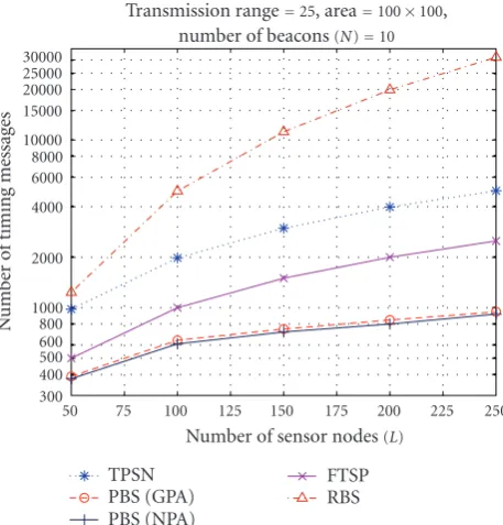
InFigure 8, the performances ofNNPAandNGPAare
com-pared with that ofNTPSNandNRBSwith respect to the
num-ber of overall sensor nodes. Again, in this simulation, the
sen-sor nodes are randomly deployed on an area of 100×100,
the transmission range of each sensor is 25, and the reference node is assumed to be located at the center of the simulation
area. The number of beacons (N) is set to be 10 in this
sim-ulation. It can be seen that PBS (with both GPA and NPA) requires a much lower number of timing messages than the other protocols, such as TPSN, FTSP, and RBS, and the gaps between the required number of message transmissions of
PBS and those of other protocols become greater as L
in-creases. Therefore, for densely deployed WSN, PBS has a sig-nificant benefit in terms of energy consumption versus either TPSN or RBS. Besides, the proposed GPA performs quite close to NPA, even though it does not require a heuristic network connection search. As mentioned before, GPA can be implemented by simply adding a groupwise connection discovery procedure to the conventional level discovery pro-cess in an arbitrary level-based synchronization protocol like TPSN.
Figure 9evaluates the performance of the proposed algo-rithms with respect to the transmission range of sensor nodes assuming the same simulation setup as in the previous fig-ure. The number of overall sensor nodes is fixed to 100 in this simulation. It can be seen that as the transmission range
(density of the network) increases,NGPAdecreases since more
sensor nodes are able to perform ROS.
Remark 2. Although the number of required messages is not a complete measure to represent the overall energy consump-tion of the network, comparing radio transmission
complex-ity is meaningful enough to evaluate the energy efficiency
since, in general, message transmission requires the largest amount of energy consumption among all possible states of a sensor node.
In [24], the authors predict energy consumption of a
sen-sor node based on a Markovian model with respect to the node state, where the idle state requires 0.01 mW, the ac-tive listening state requires 1 mW, and the transmission state requires 10 mW, respectively. Hence, message transmission consumes a magnitude greater power than message recep-tion, and a thousand times greater power than keeping the idle state.
As another example, [25] examined the current
con-sumption for transmitting a single radio message at maxi-mum transmit power on the Mica2 mote. It was shown that
50 75 100 125 150 175 200 225 250 Number of sensor nodes(L)
300 400 500 600 800 1000 2000 4000 6000 8000 10000 15000 20000 25000 30000
N
u
mber
of
timing
messages
Transmission range=25, area=100×100, number of beacons(N)=10
TPSN PBS (GPA) PBS (NPA)
FTSP RBS
Figure8: Required number of message exchanges with respect to the number of sensor nodes.
25 30 35 40 45
Transmission range 200
300 400 500 600 700 800 900 1000 2000 3000
N
u
mber
of
timing
messages
TPSN PBS (GPA)
FTSP PBS (NPA) Number of nodes(L)=100, area=100×100,
number of beacons(N)=10
Figure9: Required number of message exchanges with respect to the transmission range.
the idle state consumes instantly 100μA, the listening state
Note that there exist other models suggesting that en-ergy consumed in idle listening or eavesdropping can be significant compared with the energy required for transmis-sion, depending upon the transmission range and radio envi-ronment. In this paper, we have not considered these models. Detailed energy analysis of the proposed schemes is deferred for future investigation.
Remark 3. The synchronization accuracy is another crucial designing factor to be concerned with. In general, it depends on a variety of factors, such as the network platform and setup, channel status, and estimation schemes. The perfor-mance of existing protocols has been compared in terms of the synchronization accuracy in various references (e.g.,
[1,3,9,19]). As proven in [15,16], the accuracy of PBS is
exactly the same as that of RBS. Therefore, the issue of syn-chronization accuracy is not discussed in this paper.
4. CONCLUSIONS
In this paper, a novel time synchronization protocol has been proposed to reduce the overall energy consumption in syn-chronization based on the receiver-only synsyn-chronization ap-proach. In the Pairwise Broadcast Synchronization (PBS) protocol, a number of sensor nodes can be synchronized by only overhearing time message exchanges between pairs of nodes. Thus, PBS significantly reduces the overall network-wide energy consumption by decreasing the number of re-quired timing messages in synchronization.
For networks consisting of multiple clusters, PBS first in-vestigates a hierarchical connection tree of the network, then
applies an energy-efficient pair selection algorithm, named
groupwise pair selection algorithm (GPA), to achieve global synchronization. The proposed GPA only searches the con-nectivity among children nodes in every parent-children group of the spanning tree. Moreover, GPA can be easily combined with other level-based protocols by simply adding a groupwise connection discovery procedure. PBS requires a far smaller number of timing messages than other well-known protocols such as RBS, TPSN, and FTSP, and the ben-efits of this scheme remarkably increase as the number of sensors increases or the sensors are densely deployed.
The proposed new scheme could be fully or partially
ap-plied to improve the performance (energy efficiency) of
ex-isting protocols or for designing new protocols. Experimental performance evaluation and comparisons with other existing protocols represent an open research work for the future.
REFERENCES
[1] I. F. Akyildiz, W. Su, Y. Sankarasubramaniam, and E. Cayirci, “Wireless sensor networks: a survey,” Computer Networks, vol. 38, no. 4, pp. 393–422, 2002.
[2] N. Bulusu and S. Jha, Eds.,Wireless Sensor Networks: A Systems Perspective, Artech House, Norwood, Mass, USA, 2005. [3] B. M. Sadler and A. Swami, “Synchronization in sensor
net-works: an overview,” in Proceedings of IEEE Military Com-munications Conference (MILCOM ’06), pp. 1–6, Washington, DC, USA, October 2007.
[4] B. Sundararaman, U. Buy, and A. D. Kshemkalyani, “Clock synchronization for wireless sensor networks: a survey,”Ad Hoc Networks, vol. 3, no. 3, pp. 281–323, 2005.
[5] D. L. Mills, “Internet time synchronization: the network time protocol,” IEEE Transactions on Communications, vol. 39, no. 10, pp. 1482–1493, 1991.
[6] J. Elson, L. Girod, and D. Estrin, “Fine-grained network time synchronization using reference broadcasts,” inProceedings of the 5th Symposium on Operating Systems Design and Imple-mentation (OSDI ’02), pp. 147–163, Boston, Mass, USA, De-cember 2002.
[7] S. Ganeriwal, R. Kumar, and M. B. Srivastava, “Timing-sync protocol for sensor networks,” inProceedings of the 1st Interna-tional Conference on Embedded Networked Sensor Systems (Sen-Sys ’03), pp. 138–149, ACM Press, Los Angeles, Calif, USA, November 2003.
[8] K.-L. Noh, Q. M. Chaudhari, E. Serpedin, and B. W. Suter, “Novel clock phase offset and skew estimation using two-way timing message exchanges for wireless sensor networks,”IEEE Transactions on Communications, vol. 55, no. 4, pp. 766–777, 2007.
[9] M. Mar ´oti, B. Kusy, G. Simon, and A. L´edeczi, “The flood-ing time synchronization protocol,” inProceedings of the 2nd International Conference on Embedded Networked Sensor Sys-tems (SenSys ’04), pp. 39–49, ACM Press, Baltimore, Md, USA, November 2004.
[10] W. Su and I. F. Akyildiz, “Time-diffusion synchronization pro-tocol for wireless sensor networks,”IEEE/ACM Transactions on Networking, vol. 13, no. 2, pp. 384–397, 2005.
[11] B. M. Sadler, “Local and broadcast clock synchronization in a sensor node,”IEEE Signal Processing Letters, vol. 13, no. 1, pp. 9–12, 2006.
[12] A. Giridhar and P. R. Kumar, “Distributed clock synchroniza-tion over wireless networks: algorithms and analysis,” in Pro-ceedings of the 45th IEEE Conference on Decision and Control (CDC ’06), pp. 4915–4920, San Diego, Calif, USA, December 2006.
[13] N. Khajehnouri and A. H. Sayed, “A distributed broadcasting time-synchronization scheme for wireless sensor networks,” in Proceedings of the IEEE International Conference on Acoustics, Speech and Signal Processing (ICASSP ’05), vol. 5, pp. 1053– 1056, Philadelphia, Pa, USA, March 2005.
[14] Y.-W. Hong and A. Scaglione, “A scalable synchronization pro-tocol for large scale sensor networks and its applications,”IEEE Journal on Selected Areas in Communications, vol. 23, no. 5, pp. 1085–1099, 2005.
[15] K.-L. Noh and E. Serpedin, “Pairwise broadcast clock synchro-nization for wireless sensor networks,” inProceedings of the IEEE International Symposium on a World of Wireless, Mobile and Multimedia Networks (WoWMoM ’07), pp. 1–6, Helsinki, Finland, June 2007.
[16] K.-L. Noh, Y.-C. Wu, K. Qaraqe, and E. Serpedin, “Time syn-chronization for wireless sensor networks,” inAdaptive Sig-nal Processing for Wireless Communications, M. Ibnkahla, Ed., CRC Press, 2008.
[17] V. Paxson, “On calibrating measurements of packet transit times,” inProceedings of the ACM SIGMETRICS Joint Interna-tional Conference on Measurement and Modeling of Computer Systems (SIGMETRICS ’98), vol. 26, no. 1, pp. 11–21, Madi-son, Wis, USA, June 1998.
[19] Z. Tian, X. Luo, and G. B. Giannakis, “Cross-layer sensor net-work synchronization,” in Proceedings of the 38th Asilomar Conference on Signals, Systems and Computers (ACSSC ’04), vol. 1, pp. 1276–1280, Pacific Grove, Calif, USA, November 2004.
[20] A.-S. Hu and S. D. Servetto, “Asymptotically optimal time syn-chronization in dense sensor networks,” inProceedings of the 2nd ACM International Conference on Wireless Sensor Networks and Applications (WSNA ’03), pp. 1–10, San Diego, Calif, USA, September 2003.
[21] B. Awerbuch and R. Gallager, “A new distributed algorithm to find breadth first search trees,”IEEE Transactions on Informa-tion Theory, vol. 33, no. 3, pp. 315–322, 1987.
[22] G. Xing, C. Lu, Y. Zhang, Q. Huang, and R. Pless, “Minimum power configuration in wireless sensor networks,” in Proceed-ings of the 6th ACM International Symposium on Mobile Ad Hoc Networking and Computing (MobiHoc ’05), pp. 390–401, Urbana-Champaign, Ill, USA, May 2005.
[23] J. van Greunen and J. Rabaey, “Lightweight time synchroniza-tion for sensor networks,” inProceedings of the 2nd ACM Inter-national Conference on Wireless Sensor Networks and Applica-tions (WSNA ’03), pp. 11–19, San Diego, Calif, USA, Septem-ber 2003.
[24] M. Achir and L. Ouvry, “Power consumption prediction in wireless sensor networks,” inProceedings of the 16th ITC Spe-cialist Seminar on Performance Evaluation of Wireless and Mo-bile Systems, Antwerp, Belgium, August-September 2004. [25] V. Shnayder, M. Hempstead, B.-R. Chen, G. W. Allen, and M.