Volume 2008, Article ID 817401,13pages doi:10.1155/2008/817401
Research Article
Persistent RCSMA: A MAC Protocol for a Distributed
Cooperative ARQ Scheme in Wireless Networks
J. Alonso-Z ´arate,1E. Kartsakli,2Ch. Verikoukis,1and L. Alonso2
1Centre Tecnol`ogic de Telecomunicacions de Catalunya (CTTC), Avinguda Del Canal Ol´ımpic S/N, Parc Mediterrani de la Tecnologia, 08860 Castelldefels, Barcelona, Spain
2Department of Signal Theory and Communications, Escola Polit`ecnica Superior de Castelldefels (EPSC), Universitat Polit`ecnica de Catalunya (UPC), Avinguda Del Canal Ol´ımpic S/N, Parc Mediterrani de la Tecnologia, 08860 Castelldefels, Barcelona, Spain
Correspondence should be addressed to J. Alonso-Z´arate,[email protected]
Received 15 November 2007; Accepted 2 April 2008
Recommended by J. Wang
The persistent relay carrier sensing multiple access (PRCSMA) protocol is presented in this paper as a novel medium access control (MAC) protocol that allows for the execution of a distributed cooperative automatic retransmission request (ARQ) scheme in IEEE 802.11 wireless networks. The underlying idea of the PRCSMA protocol is to modify the basic rules of the IEEE 802.11 MAC protocol to execute a distributed cooperative ARQ scheme in wireless networks in order to enhance their performance and to extend coverage. A closed formulation of the distributed cooperative ARQ average packet transmission delay in a saturated network is derived in the paper. The analytical equations are then used to evaluate the performance of the protocol under different network configurations. Both the accuracy of the analysis and the performance evaluation of the protocol are supported and validated through computer simulations.
Copyright © 2008 J. Alonso-Z´arate et al. This is an open access article distributed under the Creative Commons Attribution License, which permits unrestricted use, distribution, and reproduction in any medium, provided the original work is properly cited.
1. INTRODUCTION
One of the unique features of the wireless channel is its inherent broadcast nature. The air interface is a common communication channel that is shared among all the stations in a wireless network. Therefore, all the transmissions can be overheard by any station which receives enough signal strength from the transmitter. This broadcast nature poses severe challenges in the field of security, but on the other hand, opens a wide and interesting line of research targeted at exploiting all the potential benefits of those schemes that promote stations to help each other in the communica-tions. In multiuser environments, these cooperative schemes constitute a potential alternative to overcome the practical implementation drawbacks found out when experimenting with multiple input multiple output (MIMO) techniques using relatively small devices.
The improvement induced by exploiting cooperation in wireless networks can be attained in terms of higher transmission rate, lower transmission delay, more efficient power consumption, or even increased coverage range. In
the example illustrated inFigure 1, all the stations located in the transmission range of the source station (idealized in the figure with the solid circle centered at the source station) can collaborate to convey a message to a destination out of the transmission range of the transmitter. These helping stations are typically referred to as the relays.
The fundamental theory behind the concept of coop-eration has been deeply studied among researchers during the last years [1–6] and now, it is currently one of the hottest topics in several engineering fields ranging from information theory to computer science. However, there is still a long way ahead in bringing to life all these theoretical concepts and developing efficient protocols that can exploit the inherent broadcast nature of wireless links to improve the performance of networks operating over the air interface. Among other open issues, the design of efficient medium access control (MAC) protocols required to manage the relay retransmissions is yet a topic of great interest.
Source
Destination Relay
Relay
Figure1: Cooperative scenario.
in wireless networks. These schemes exploit the broadcast nature of the wireless channel in the following manner; once a destination station receives a data packet containing errors, it can request a set of retransmissions from any of the relays which overheard the original transmission. retransmissions from the relays might be attained at higher transmission rates and they may allow for the exploitation of either space or time diversity. With such a distributed scheme, it is possible to improve the channel usage as well as to extend the coverage of the transmissions. Consider the example illustrated inFigure 2. It represents a multirate system, such as the IEEE 802.11 or WiMax standards, where the achievable transmission rate between any pair of source and destination stations depends, among other factors, on the signal strength at the receiver. Typically, the higher the distance between transmitter and receiver, the lower the achievable transmission rate is for a given network configuration. This allows for idealizing a scenario whereby it is possible to define different transmission rate areas surrounding any transmitting station, as illustrated in the example of Figure 2. The station S represents a source station attempting to transmit a data packet to the destination stationD. There are four available transmission rates R4 > R3 > R2 > R1. The station Dlies within the
R1 region of the station S, and thus communication will
be performed at the lowest available transmission rate. This means, in turn, that a retransmission from the stationSto the stationDwill have the highest possible cost in terms of channel time use. However, if the stationDrequests different retransmissions from the set of relay stationsr1,. . .,r4, with
whom communications might be performed at higher data transmission rates, for example, atR4, then, the total time
required for the complete transmission process may be reduced, and thus, the channel usage increased.
Although it would be desirable to be able to tailor near-optimum protocols to get the most of the cooperative-prone nature of wireless communications, technological evolution is somehow constrained by economical drivers and the so-called imperative backwards compatibility. It is not possible
R1
R2
R3
R4
S
D R4
R4
R4
R4 r1
r2
r3
r4
Figure2: Example of cooperative scenario.
to deploy completely novel devices as technology moves forward, and thus, it is of utmost interest to develop novel proposals that can at least coexist with currently available technology. With this idea in mind, a novel MAC protocol that can obtain the benefits of a distributed cooperative ARQ scheme while still using widely deployed commercial devices for wireless local area networks (WLANs) based on the standard IEEE 802.11 for WLANs [7] is presented in this paper. The new proposal is called persistent relay carrier sensing multiple access (PRCSMA) protocol, and it is based on the seminal idea outlined in [8]. In addition, the protocol is analytically modeled and a performance discussion of the protocol is also presented.
It is worth mentioning that according to the specific way, the selected relay stations handle the original signal and the way the different copies are combined to reconstruct the original message at the destination station, it is possible to classify cooperative (relay) techniques as (i) amplify and forward techniques, when the relays send an amplified version of the original message; (ii) compress and forward techniques, when the relays send a compressed version of the original transmitted signal, and (iii) decode and forward techniques, when the relays send recoded copies of the original message. Note that using decode and forward, the recoding process can be done on the basis of repeating the original codification, recoding the original data (or only a relevant part of it), or using more sophisticated space-time codification [9]. The MAC protocol presented in this paper could run on top of any of these schemes, which are, indeed, transparent to the MAC operation.
transmission delay considering the cooperation scheme. System level simulations are presented inSection 6in order to validate the accuracy of the proposed model and to evaluate the performance of the protocol under different configurations. Finally, Section 7 concludes the paper and gives some final remarks.
2. RELATED WORK
The concept of distributed cooperative ARQ has been already tackled in the past from a fundamental point of view, considering simplified network topologies, and considering ideal scheduling among the relays [10–15]. The gains of a cooperative ARQ scheme analyzed in terms of improved probability of error are discussed in [10]. In [11], the signal-to-noise ratio (SNR) gain and the average number of required retransmissions of a single source cooperative ARQ protocol are studied. In [12], the performance of different cooperative protocols is derived in terms of outage probabil-ity and SNR gain, while in [13], the saturation throughput of three double-source cooperative ARQ protocols is presented. Cerutti et al. present in [14] a delay model for single-source and single-relay cooperative ARQ protocols. In [15], Morillo-Pozo et al. propose a collaborative ARQ protocol that exploits diversity through collaboration in wireless
networks. They demonstrate that when M neighboring
stations collaborate using the proposed algorithm can get the same efficiency as an array ofM antennas. Some other works have been focused on the relay selection criteria within the context of distributed cooperative ARQ schemes. For example, in the works presented in [16,17], an opportunistic forwarding scheme is presented wherein the best candidate to retransmit is selected whenever a communication has failed. On the other hand, in [18,19], a scenario wherein a set of the best candidates is selected, therein referred to as a cloud of relays, is discussed.
Previous work has put in evidence that distributed cooperative ARQ schemes may yield improved performance, lower energy consumption and interference, as well as increased coverage area by allowing communication at lower SNRs. However, up to the knowledge of the authors, there are no MAC protocols conceived to execute distributed cooperative ARQ schemes in wireless networks and to attain the achievable benefits discussed in the aforementioned research works. This is the main motivation of the work presented in this paper. The focus is on the contention process that takes place in scenarios such as the ones in [18,19], where the relays should contend for the access to the channel.
It is worth mentioning that there exists in the literature a completely different family of cooperative MAC protocols [20–26] which have not been designed for the execution of distributed cooperative ARQ schemes in wireless networks, but they are aimed at solving other kind of interesting cooperative issues. In particular, in [20] two versions of the CoopMAC protocol are designed in the context of 802.11b WLANs in order to solve the performance anomaly problem induced by the multirate capability of the distributed coor-dination function (DCF) of the standard [7]. Korakis et al.
implemented the protocol in actual WLAN cards, as reported in [21]. The main contribution in [21] is the description of the overall implementation process and the limitations found when attempting to implement the protocol. These limitations were mainly due to the constraints imposed by the time sensitive tasks performed by wireless cards’ firmware. In addition, the CoopMAC was adapted to wireless networks using directional antennas in [22]. On the other hand, both the cooperative-MAC (CMAC) and forward error correction CMAC (FCMAC) protocols were presented in [23] within the context of 802.11e networks to improve the performance and to ensure a certain quality of service. In [24], the cooperative diversity medium access with collision avoidance (CD-MACA) protocol is proposed within the context of wireless ad hoc networks operating over the carrier sensing multiple access with collision avoidance (CSMA/CA) protocol. Although the general idea of CD-MACA is rather interesting, the definition in [24] is quite general and several implementation details are not considered. From an energy-efficient perspective, another cooperative MAC protocol is also presented within the context of ad hoc networks in [25]. This proposal integrates cooperative diversity into two different wireless routing protocols by embedding a distributed cooperative MAC. In [26], a cooperative MAC protocol was presented within the context of a mesh network formed by an access point, a number of regular stations, and one fixed wireless router (relay).
Therefore, and as aforementioned, the PRCSMA ana-lyzed in this paper has been designed as a MAC protocol to execute a distributed cooperative ARQ scheme in wireless networks. Since it is based on the IEEE 802.11 MAC protocol,Section 3is devoted to summarize the fundamental operational rules of the standard.
3. IEEE 802.11 DCF MAC OVERVIEW
The MAC protocol defined in the standard IEEE 802.11 for WLAN is summarized in this section. The focus has been put on the DCF, which is the one considered for ad hoc operation. Further details can be found in [7]. An example of operation of the protocol is illustrated inFigure 3.
Any station with data to transmit executes a clear channel assessment (CCA) by which it listens to the channel for a DCF interframe space (DIFS). If the channel is sensed free during this DIFS period, the station initiates the transmission of data. Otherwise, it executes a binary exponential backoff algorithm by which any station suffering a collision or a failed transmission, upon detection of the failure, sets a backoff counter at a randomized value within the interval [0,CW]. CW is referred to as the contention window, and it is initially set to a predefined value CWmin. As long as the channel is
sensed idle, the backoff counter is decreased by one unit, referred to at the PHY layer as slot time and typically denoted by σ. Upon expiration of the timer, the station transmits again. In the case of failure, the CW is doubled up, up to a given maximum value CWm =2m·CWmin = CWMAX, and
Source Destination Others
DIFS SIFS RTS
CTS
Data
ACK Network allocation vector (NAV)
Contention window Contention window Figure3: IEEE 802.11 MAC protocol.
Therefore, the CW can be expressed and summarized as
CWi=min
2iCW
min, CWMAX
. (1)
Any given packet is discarded aftermfailed transmission attempts and the CW is reset to the initial value CWmin in
order to process the next packet.
Two transmission modes of operation are defined in the standard, namely, the basic access and the collision avoidance access, which is aimed at combating with the presence of the hidden and exposed terminals. In the former method, data packets are directly transmitted when trying to seize the channel, while in the later method a handshake (request-to-send (RTS)-clear-(request-to-send (CTS)) between source and destination is established before initiating the actual data transmission. Upon the correct reception of a data packet, the destination station sends back an ACK packet after a short interframe space (SIFS). This SIFS is necessary to compensate for propagation delays and radio transceivers turn around times to switch from receiving to transmitting mode. It is worth noting that due to the fact that an SIFS is shorter than a DIFS, acknowledgments are given priority against regular data traffic.
Another relevant feature of the standard is the virtual carrier sensing mechanism, by which stations not involved in an ongoing transmission defer from attempting to transmit during the time the channel is expected to be used for an effective transmission between any pair of source and destination stations. To do so, stations update the network allocation vector (NAV) which counts for the time the channel is expected to be occupied.
4. PERSISTENT RCSMA
4.1. Protocol description
The main design goal of PRCSMA is to enable IEEE 802.11 stations to ask their neighborhood to cooperate upon the erroneous reception of a data packet. This cooperation will result in a distributed cooperative ARQ scheme. Therefore, the key objective is to modify the legacy IEEE 802.11 MAC rules to enable cooperation among the stations in a way that they could be somehow backwards compatible.
When using PRCSMA, all the stations must listen to every ongoing transmission in order to be able to cooperate if required, that is, they should operate in promiscuous mode. In addition, they should keep a copy of any received data packet (regardless of its destination address) until it is acknowledged by the destination station. It is important to note that the term destination station will be used hereafter
to denote the next-hop destination of a packet, as specified by the routing protocol, which may not be the final destination station of a packet. On the other hand, the copy retained by the relays might be stored at each station data buffer or in a different dedicated queue.
Whenever a data packet is received with errors at the destination station, a cooperation phase can be initiated. The error-check could be performed by cross-checking a cyclic redundancy code (CRC) attached to the header of the packet or any other equivalent mechanism. This cooperation phase will be initiated by the intended destination station by broadcasting a claim for cooperation (CFC) message in the form of a control packet after sensing the channel idle for an SIFS period. Regular data transmissions in IEEE 802.11 are done after a longer silence period (DIFS), and thus cooperation phases are given priority over regular data traffic.
The CFC packet invites all the stations to become active relays for the communication process as long as they meet some relay selection criteria, not specified in the basic definition of PRCSMA. Different schemes for selecting a nonempty set of the most appropriate relays were discussed by the authors in [27]. It is worth mentioning that although the optimal scheme would consist in selecting the best relay for each cooperation phase, the approach in PRCSMA is to select a set of the most appropriate active relays in order to loosen the requirement of selecting exactly the best candidate in each moment [27]. An interesting open line of research will be focused on assessing the tradeoffbetween the costs of selecting the best relay against the time required to solve the contention among a set of selected relays.
Upon the reception of the CFC, all the stations which become active relays form the so-called relay set and get ready to forward their cooperative information. Although the specific PHY forwarding strategies applied at the relays and the reconstructing mechanism implemented at the destination station are out of the scope of the basic definition of PRCSMA, it is worth recalling that the retransmitted copy may be simply an amplified version of the original received packet at each relay, a compressed version of the received signal, a recoded version of the information, or any kind of space-time coded packet (see Section 1). For convenience, the packet transmitted by any relay will be referred to as a cooperative packet.
(1) there is no expected ACK associated to each transmit-ted cooperation packet;
(2) since the subnetwork formed by the relay set works in saturation conditions, that is, all the relay stations have a data packet ready to be transmitted, it is necessary to execute a backoffmechanism at the beginning of the cooperation phase in order to avoid a certain initial collision. Therefore, those active relays which do not have an already set backoffcounter (from a previous transmission attempt) set it up and initiate a random backoffperiod before attempting to transmit for the first time. On the other hand, those relays which already have a nonzero backoffcountervalue keep the value upon the initialization of a cooperation phase.
A cooperation phase is ended whenever either the desti-nation station is able to decode the original data packet by properly combining the different cooperative packets received from the relay set or a certain maximum coop-eration timeout has elapsed. In the former case, that is, a successful cooperation phase, an ACK packet is transmitted by the destination station. In the latter case, that is, if the original packet could not be decoded, a negative ACK (NACK) is transmitted by the destination station. In any case, all the relays popout the cooperative packet from their queue upon the end of a cooperation phase.
According to all this operation, three implementation issues should be considered.
(1) The CFC can be a regular RTS packet, using the empty field for address 4, as done in [21], to distinguish the packet from a normal RTS.
(2) As long as there is at least one active relay, the persistent behavior of PRCSMA eliminates the prob-ability that the destination station does not receive the required amount of cooperation retransmissions [27] by pretending there are infinite stations trying to cooperate.
(3) The active relays could execute either the basic access or the collision avoidance (COLAV) mode during a cooperation phase. On the one hand, as data bit rates become higher, it becomes more critical to reduce the overhead associated to the payload in order to avoid an unnecessary waste of the radio resources; therefore, it would be desirable to use the basic access mode. However, the COLAV mechanism acts as a protection mechanism against the hidden terminal problem, and thus, it will be necessary to consider the use of the RTS-CTS handshake also for the relays retransmissions in multihop networks.
4.2. Operational example
For the sake of understanding of PRCSMA, and before getting into the insights of the proposed analytical model, an example of operation of PRCSMA is presented in this section. A simple network layout with 4 stations is considered, all of them in the transmission range of each other. The basic access mode is considered, and a source
station (S) transmits a data packet to destination station (D) with the support of both relaysR1andR2. The cooperation phase is represented inFigure 4, and explained as follows:
(1) at instantt1, stationSsends a data packet to stationD;
(2) upon reception, at instant t2 station D broadcasts a
CFC packet asking for cooperation to those stations in its neighborhood (R1andR2in this example); (3) stationsR1andR2receive the CFC packet and set up
their backoffcounters CW1and CW2at instantt3;
(4) at instantt4, the backoffcounter ofR1expires (CW1),
andR1attempts a cooperative transmission;
(5) at instantt5,R2resumes the backoffcounter whileR1
resets a new value for its backoffcounter (CW1); (6) at instantt6, the backoffcounter ofR2expires andR2
attempts a cooperative transmission;
(7) at instantt7,R1resumes the backoffcounter andR2
resets a new backoffcounter;
(8) at instantt8, the backoffcounter ofR2expires andR2
attempts a cooperative transmission;
(9) at instantt9, stationDis able to properly decode the
original data packet and sends back an ACK packet, indicating the end of the cooperation phase. All the stations then know that the cooperation phase has ended.
5. PRCSMA ANALYTICAL MODEL
5.1. Overview and motivation
It is always interesting to know, or at least to predict, the cost of retransmitting when executing ARQ schemes. In the distributed and cooperative scenario proposed in this paper, any destination station should assess the suitability of initiating a cooperative phase before actually sending the CFC. Therefore, accurate models to estimate the average delay associated to the distributed cooperative ARQ scheme, seen as the expected duration of the whole packet transmis-sion time, including the cooperation phase, are required. In addition, these models may allow optimizing any given figure of merit of the system (such as the network throughput). Accordingly, an analytical model to evaluate the average distributed cooperative ARQ packet transmission delay when using PRCSMA is presented in this section.
As mentioned before, upon the reception of a CFC packet, all those stations that accomplish with some certain relay selection criteria become active relays and they will attempt to transmit their cooperative packet as many times as necessary until the cooperation phase is over. Therefore, the network will be in saturation conditions for the whole cooperative phase until the destination station is able to decode the packet. As a consequence, the relay set during a cooperation phase can be seen as a saturated network, and thus, existing analytical models for saturated IEEE 802.11 networks can be used as the foundations to develop the PRCSMA analytical model.
Cooperation phase
t1 t2 t3 t4 t5 t6 t7 t8 t9 Time
S: Source
D: Destination
R1: Relay1
R2: Relay2 Data
CFC SIFS
Wait for cooperation Data
Data Data
ACK
DIFS DIFS DIFS
Min (CW1, CW2)
Min (Max(CW1-CW2,CW2-CW1),CW1)
Max (Max(CW1-CW2,CW2-CW1)-CW1, CW1-Max(CW1-CW2,CW2-CW1)) Figure4: PRCSMA example of operation.
of an individual station with a Markov chain, and then use it to derive the overall network performance metrics. The main interest now is in deriving the average delay required to achieve a given average number of successful consecutive transmissions among all the stations forming the relay set. Therefore, although the individual station approach is useful to model PRCSMA, up to the knowledge of the authors, the derivation of this average distributed cooperative ARQ packet transmission delay, seen as the average duration of a complete data packet transmission time, including the cooperation phase that involves the relays, has not been tackled so far. This paper presents the analysis of this figure of merit for an IEEE 802.11-PRCSMA network.
5.2. Markov chain model
The backoff counter of a single PRCSMA station can be modeled using the embedded Markov chain presented and analyzed by Wu et al. in [29], and which is illustrated in Figure 5 to facilitate the understanding of the presented analysis. Each of the states represents a different value that the backoff counter of a station can take. Any pair (i,j) denotes the current value of the backoff counter i at the backoff stage j. Accordingly, the state (0, 0) represents a transmission attempt. A comprehensive description of the chain can be found in [29].
A time-slotted system is considered where a total ofn stations are within the transmission range of each other. A slot is defined as the unit of time between consecutive backoff counter decrements and it has a different duration depending on whether a slot is idle or busy. The main assumption of the model is that the probability of having a collision when attempting to transmit in a given time slot,p, is considered to be constant along time.W0 = CWmin is the size of the
initial CW,mis the maximum backoffstage, andmis the maximum number of retransmissions before discarding a packet. It is worth noting that ifm > m, then the backoff window will remain at the maximum stage (m) for the last m−mtransmission attempts. Therefore, the probability that
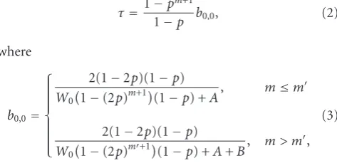
one station attempts to transmit in a given slot, denoted by τ, is derived in [29] as
τ=1−pm+1
1−p b0,0, (2)
where
b0,0= ⎧ ⎪ ⎪ ⎪ ⎪ ⎪ ⎪ ⎨ ⎪ ⎪ ⎪ ⎪ ⎪ ⎪ ⎩
2(1−2p)(1−p) W0
1−(2p)m+1 (1−p) +A, m≤m
2(1−2p)(1−p) W0
1−(2p)m+1 (1−p) +A+B, m > m ,
(3)
andA=(1−2p)(1−pm+1) andB=W
02mpm+1(1−2p)(1− pm−m). Therefore, the probability of collision pin a given slot is equal to
p=1−(1−τ)n−1. (4)
The probability that at least one of thenstations attempts to transmit in a given slot,Ptr, can be expressed as
Ptr=1−(1−τ)n, (5)
and the probability of having a successful slot given that a station transmits,ps, is given by
ps= nτ
(1−τ)n−1
Ptr .
(6)
Finally, the probabilities of having an idle (Pi), successful (Ps), or collided (Pc) slot can be then written as
Pi=1−Ptr,
Ps=Ptr·ps=nτ(1−τ)n−1,
Pc=Ptr(1−ps).
(7)
1/W
0 1/W0 1/W0
1−p (0, 0) 1 (0, 1) 1 . . . 1 (0,W0−1)
p/Wi−1 p/Wi−
1
p/Wi−1
1−p (i−1, 0) 1 (i−1, 1) 1 . . . 1 (i−1,Wi−1−1)
p/Wi p/Wi p/Wi . . .
1−p (i, 0) 1 (i, 1) 1 . . . 1 (i,Wi−1)
. . . . . . . . . . . .
(m, 0) 1 (m, 1) 1 . . . 1 (m,Wm−1)
Figure5: Wu’s Markov chain to model the backoffwindow of the IEEE 802.11 standard.
5.3. Average distributed cooperative ARQ packet transmission delay analysis
The average distributed cooperative ARQ packet transmis-sion delay of PRCSMA is defined as the average duration of the first failed transmission plus the average time required to complete a successful cooperation phase given an aver-age number of retransmissions, E[r], required to properly decode a packet received with errors at destination. This average delay will be denoted by E[TCOOP]. It is worth
mentioning that the value of E[r] will depend on (i) the channel conditions between the relays and the destination stations; (ii) the specific cooperative scheme applied at the PHY layer, and (iii) the used relay selection criteria [27]. Therefore, the value ofE[TCOOP] can be calculated as
ETCOOP
=ETmin
+ETcont
, (8)
whereE[Tmin] is the expected minimum distributed
coop-eration ARQ packet transmission delay, which would be only achievable in the case of attaining a perfect scheduling among all the active relays, that is, avoiding contention. However, the perfect scheduling among the relays required to attain this ideal minimum average delay is impossible to attain without perfect a priori knowledge of the relays. Therefore, a con-tention process among the relay stations is unavoidable. This contention may lead to silence periods as well as collisions that will increase the average distributed cooperative ARQ packet transmission delay. The termE[Tcont] will be used to
denote the expected delay caused by the contention among the relays when accessing to the channel.
The termE[Tmin] can be computed as
ETmin
=T0+TCFC+E[r]TDR+TACK+ 4TSIFS, (9)
whereT0 is the duration of the first transmission from the
source station to the intended destination station.TCFCand TACKare, respectively, the transmission time of the CFC and
the ACK packets.TDRis the time required to retransmit a
sin-gle packet considering that all the relay stations transmit their cooperative packets at a same common transmission rate. This value depends on whether the basic access mechanism or the collision avoidance handshake RTS/CTS is executed by the relays, and it is equal to TDR|BASIC orTDR|COLAV,
respectively, and calculated as
TDR|BASIC=TDIFS+TDATA+TSIFS,
TDR|COLAV=TDIFS+TRTS+TSIFS+TCTS+TSIFS
+TDATA+TSIFS,
(10)
where TDIFS and TSIFS are, respectively, the duration of
DIFS and SIFS silence periods, and TRTS and TCTS are the
transmission times of an RTS and CTS packets. TDATA is
the duration of the transmission of a data packet (using the maximum available transmission rate between the relays and the destination).
On the other hand, and as long as the contention time of a packet is independent of the contention time of any other packet, which is true within the context of IEEE 802.11 [7], the value ofE[Tcont] can be calculated as
ETcont
=E[r]ETc
where E[Tc] is the average contention time required to transmit a single packet among all the relays. Therefore, the interest now is on calculating the average time elapsed between successful transmissions. This time is composed of a number of idle or collided slots of different durations, and can be derived as follows. According to the model presented in Section 5.2, a successful transmission is carried out in a given slot with a probability Ps. Therefore, the average number of slots before having a successful transmission is denoted byE[X] and it can be calculated as
E[X]=
∞
k=0
(k+ 1)1−Ps kPs
=Ps
− ∂
∂Ps ∞
k=0
1−Ps k+1
= 1
Ps.
(12)
According to this, the average number of nonsuccessful slots before having a successful transmission is equal toE[X]−1. Therefore, the total contention time will be equal to
ETc
=E[X]−1 ETslotnon successful slot
, (13)
whereE[Tslot|non successful slot] is the average duration of a slot
given that the slot is not successful. A slot is not successful if it is idle or collided. As previously discussed, a given slot will be idle with probabilityPi, and its duration will be equal to the basic slot time, denoted byσ. On the other hand, a given slot will suffer a collision among stations with probabilityPc. As for the case of the duration of a successful transmission expressed in (10), the duration of a collision depends on whether collision avoidance is used or not, and is given in (14) as
Tcol|BASIC=TDIFS+TDATA+TSIFS,
Tcol|COLAV=TDIFS+TRTS+TSIFS+TCTS TIMEOUT.
(14)
The termTCTS TIMEOUTis the duration of the CTS time-out
period after with a collision is considered to have occurred if no CTS packet is received by the station transmitting the corresponding RTS [7].
Applying Bayes’ theorem, the average duration of any slot given that the slot is either idle or collided can be expressed as
ETslotnon successful slot
=
Pi 1−Ps
σ+
Pc 1−Ps
Tcollision.
(15)
Finally, the average total contention time can be rewritten as
ETcont
=E[r]
1 Ps−
1
Pi 1−Ps
σ+
Pc 1−Ps
Tcollision
.
(16)
It is worth recalling that probabilitiesPs,Pc,and Pi, calculated with (7), depend on the number of active relays n, the initial backoffwindowW0, the maximum backoffstagem,
and finally the maximum number of transmission attempts before discarding a packetm.
6. MODEL VALIDATION AND PERFORMANCE EVALUATION
6.1. Introduction and system model
The aim of this section is twofold: first, to validate the accu-racy of the model presented inSection 5through computer simulations and, second, to evaluate the performance of the PRCSMA under different network configurations. To this end, a custom-made C++ simulator has been implemented to simulate a network formed by a total ofN stations, all within the transmission range of each other, and wherein all the stations have always a packet ready to be transmitted. Note that under these saturated conditions, all the stations will always have a nonzero value of the backoffcounter unless they are actually transmitting.
In order to focus on the analysis the contention problem among the relays and to avoid obscuring the performance evaluation with other system parameters, the following assumptions have been made.
(i) Original transmissions from a source station to any other destination station are always received with errors, and thus, a cooperation phase is always initiated upon the reception of an original packet. In this way, only the cooperative behavior is studied. These transmissions are performed at two constant common transmission rates, referred to as themain control rate andmain data rate, indicating the bit rate for both the control and data plane transmissions, respectively. (ii) Relay retransmissions are assumed to be error-free.
Although this assumption may seem too restrictive, the objective is to focus on the role that the MAC plays on the performance, irrespectively of the channel conditions, assuming that they will be similar for relays close to the destination station. The parameter consid-ered in this paper for the performance evaluation will be the average number of required retransmissions by the destination station in order to properly decode a packet originally received with errors (E[r]). Note that in a realistic scenario, this value will be determined by the specific cooperative scheme applied at the PHY layer, together with the actual channel conditions between the relays and the destination station. These transmissions are performed at two constant common transmission rates, referred to as therelay control rate andrelay data rate, indicating the bit rate for both the control and data plane transmissions, respectively.
Table1: System parameters.
Parameter Value Parameter Value MAC header 34 bytes DATA packets 1500 bytes PHY header 96μs SlotTime, SIFS 10μs
ACK, CFC 14 bytes DIFS 50μs
RTS 20 bytes CTS 14 bytes
standard IEEE 802.11g [33], which allows for backwards compatibility with IEEE 802.11b stations.
6.2. Evaluation procedure
The performance evaluation presented in this paper is focused on the average distributed cooperative ARQ packet transmission delay, as defined inSection 5.3. This value has been computed in different evaluation cases by varying the following parameters:
(1) the number of active relays upon cooperation request; (2) the transmission rates of both the main link (source-destination) and the relay transmissions (relays-destination), using the sets of rates specified inTable 2; (3) the average number of required retransmissions upon cooperation request, E[r]. It is worth recalling that although this value is not a tunable parameter, and it is fixed by the network topology and conditions, it may be selected to a certain extent by appropriately selecting both the PHY cooperative scheme and the relay selection criteria, taking into account the net-work configuration;
(4) the access method of the relays: basic access or collision avoidance access with RTS/CTS exchange;
(5) the size of the contention windows used by the relays.
In order to study the influence of these parameters, several evaluation cases have been considered. In each case, the parameter under evaluation has been modified whereas the rest of the parameters have been kept constant and will be specified in the following subsections. They are also summarized inTable 3.
6.3. Evaluation case 1: data and control transmission rates
In order to evaluate the impact of the transmission rates on the performance of the PRCSMA, the initial CW has been set to 32 and the number of active relays (stations contending for the channel) in each cooperation phase has been set to 10. All the relay stations use the basic access method to get access to the channel.
The average distributed cooperative ARQ packet trans-mission delay is illustrated in both Figures 6 and 7 as a function ofE[r] and for different sets of transmission rates. First, it should be emphasized the almost perfect match between the analytical model and the simulations. This accuracy will be also contrasted along the other subsections of this performance evaluation.
Average number of required retransmissions (E[r])
1 2 3 4 5
0 10 20 30 40 50 60 70 80 90 100
A
ver
age
dist
ribut
ed
co
oper
ati
ve
A
R
Q
pack
et
tr
ansmission
dela
y
(ms)
CW=32; active relays=10; basic access
Traditional ARQ delay 1–54 Distributed ARQ delay 1–54 sim. Distributed ARQ delay 1–54 model Traditional ARQ delay 6–54 Distributed ARQ delay 6–54 sim. Distributed ARQ delay 6–54 model
Figure6: Average distributed cooperative ARQ packet transmission delay as a function of the transmission rate (relay low-rate regime).
Average number of required retransmissions (E[r])
1 2 3 4 5
0 1 2 3 4 5 6
A
ver
age
dist
ribut
ed
co
oper
ati
ve
A
R
Q
pack
et
tr
ansmission
dela
y
(ms)
CW=32; active relays=10; basic access
Traditional ARQ delay 24–54 Distributed ARQ delay 24–54 sim. Distributed ARQ delay 24–54 model Traditional ARQ delay 54–54 Distributed ARQ delay 54–54 sim. Distributed ARQ delay 54–54 model
Figure7: Average distributed cooperative ARQ packet transmission delay as a function of the transmission rates (relay high-rate regime).
As it could be expected, the ratio between the main trans-mission rates and the relays transtrans-mission rates determines how efficient the distributed ARQ mechanism is in com-parison to the traditional noncooperative ARQ approach, where the retransmissions are only requested from the source at the best available transmission rate between the source and the intended destination station and without contention between consecutive retransmissions.
Table2: Sets of transmission rates (Mbps).
Name Main control rate Main data rate Relay control rate Relay data rate
1–54 1 1 6 54
6–54 6 6 6 54
24–54 6 24 6 54
54–54 6 54 6 54
Table3: Simulation parameters for each evaluation case.
Evaluation
Data/Ctr transmission rates
(Mbps)
E[r] Relays access method Size of the initial CW (slots)
Number of active relays in each cooperation
phase
Case 1 1–54, 6–54, 24–54,
54–54 1, 2, 3, 4, and 5 BASIC 32 10
Case 2 1–54, 6–54, 24–54,
54–54 1, 2, 3, 4, and 5 BASIC 32 10
Case 3 24–54 3 BASIC/COLAV 16 1 to 10
Case 4 24–54 3 BASIC 16, 32, 64, 128,
256, and 512 1, 5, and 10
of the main link), whenE[r] is 5, the distributed approach reduces the average packet transmission delay in a factor 4 compared to the traditional ARQ scheme. On the other hand, at the limit where the relay stations transmit at the same rate that the source station, the total delay in the distributed scheme is higher due to the cost of coordinating the set of relays.
It is worth mentioning that, as it could be expected, if E[r] is very low, then the efficiency of the distributed ARQ scheme becomes similar to that of a traditional ARQ scheme. This is due to the fact that, despite the faster relay retransmissions, the overhead associated to the protocol does not payoff the reduction of the actual data retransmission time.
In the case of networks where the data transmission rate of each station is selected as a function of the channel state between source and destination stations, as in IEEE 802.11 WLANs, the behavior of PRCSMA shows that distributed cooperative ARQ schemes would be especially beneficial for those stations located far away, in radio-electric terms, from a transmitting station. Note that these stations will be prone to transmit at low transmission rates, and therefore, they could benefit from the faster retransmissions performed by relay stations halfway from the source station. In addition, the whole network, that is, the rest of the stations, will benefit from this scheme in the sense that faster transmissions will occupy the channel for shorter periods of time.
6.4. Evaluation case 2: average number of required retransmissions (E[r])
The same scenario as the one in Section 6.3 has been considered in this subsection.
It can be inferred from Figures6and7that the coop-erative distributed ARQ packet transmission delay grows linearly withE[r] in PRCSMA.
Consider a network where the relays can transmit at very high transmission rates in comparison to the main transmission link. In this scenario, the cost of increasing in one unit the value of E[r] is very low in terms of delay. Therefore, it may be concluded that in this situation, it would be possible to employ simpler cooperative schemes at the PHY layer even if they may require higher values ofE[r] in order to properly decode an erroneous message.
However, if the transmission rates of relays are com-parable to that of the main link (source-destination), then the cost of a retransmission could spoil the benefits of the distributed cooperative ARQ scheme. Therefore, the use of cooperative schemes that can reduce the value of E[r] should be employed, for example, by executing more efficient cooperative schemes at the PHY layer.
6.5. Evaluation case 3: the relays access method
In this case, all the relays use an initial CW set to 16. The selected transmission rate set has been 24–54 Mbps (main-relays).
Number of active relays
1 2 3 4 5 6 7 8 9 10
1.5 2.5 3.5 4.5 5.5 6.5
A
ver
age
dist
ribut
ed
co
oper
ati
ve
A
R
Q
pack
et
tr
ansmission
dela
y
(ms)
CW=16; rate set 24–54
E[r]=1, Basic
E[r]=2, Basic
E[r]=3, Basic
E[r]=4, Basic
E[r]=5, Basic
E[r]=1, COLAV
E[r]=2, COLAV
E[r]=3, COLAV
E[r]=4, COLAV
E[r]=5, COLAV
Figure8: Performance of PRCSMA with different access methods (BASIC versus COLAV).
which yields a high probability of collisions, the basic access method outperforms the collision avoidance in all cases. This is mainly due to the fact that the collisions in the control plane (at lower transmission rates) have a bigger cost in terms of transmission time than those in the data transmission plane (at much higher transmission rates) despite the fact that the RTS and CTS packets are shorter than data packets. Therefore, it is possible to conclude that the COLAV mechanism adds significant overhead to the communication process and compromises the benefits of the distributed cooperative ARQ scheme.
6.6. Evaluation case 4: the size of the contention window (CW)
In this case, the relay stations use the basic access mode during a cooperation phase. The average number of required retransmissions has been set to 3 and three curves represent the delay with 1, 5, or 10 active relays in each case. The transmission rate set used in these simulations is 24–54 Mbps (main-relays).
The average distributed cooperative ARQ packet trans-mission delay as a function of the size of the CW is illustrated inFigure 9. For the single-relay case, the average delay grows linearly with the size of the CW. Note that, the average time wasted due to the backoff will be equal to half the value of the CW, which corresponds to the expectation of the selected backoffcounter. The most interesting deduction can be extracted for low values of the CW. When the size of the CW is comparable to the number of active relays, the probability of collision grows remarkably, and thus, the cooperation delay is also increased. As an example, we can see that when the size of the CW is set to 16 and the number of relays is 10, the delay is higher than when only 5 active
Size of the contention window (CW)
16 32 64 128 256 512
3 4 5 6 7 8 9 10 11
A
ver
age
dist
ribut
ed
co
oper
ati
ve
A
R
Q
pack
et
tr
ansmission
dela
y
(ms)
Basic access,E[r]=3, rate set 24–54
1 relay sim. 1 relay model 5 relays sim.
5 relays model 10 relays sim. 10 relays model
Figure9: Average distributed cooperative ARQ packet transmission delay as a function of the size of the contention window.
relays are required. Therefore, the size of the CW should be properly selected as a function of the number of active relays. Higher values of the CW will lead to too much time wasted in backoffperiods, while lower values of the CW will lead to increase the number of collisions. It is worth mentioning that in the case of not being able to operate at the optimum value of the CW, it would be more convenient to use higher values of the CW, since in both basic and collision avoidance access method, the cost of a collision is much higher than the cost of some extra backoffslots.
7. CONCLUSIONS
The PRCSMA protocol and its analytical performance model have been presented in this paper as an innovative solution to allow cooperative behavior in standardized IEEE 802.11 networks. By using PRCSMA, it would be possible to exploit the broadcast nature of wireless communications to save energy, to reduce interference to other systems, to increase performance and reliability of wireless communications, and to increase the range of the transmissions.
as a function of the number of activated relays for each cooperation phase in order to avoid either wasted time due to referral periods or existence of a high probability of collision. In any case, since collisions have a higher cost in terms of channel usage than idle periods due to unnecessary backoffdeferral periods, a PRCSMA-based network should be configured with relatively high values of the contention windows compared to the average number of active relays in a cooperation phase.
Future work will be aimed at extending the analysis herein presented to multihop scenarios where the presence of hidden terminals may hamper regular communications. Another line of research will be aimed at analyzing the benefits of the proposed distributed ARQ scheme in terms of energy consumption and coverage extension.
ACKNOWLEDGMENTS
This work has been funded by the Research Projects LOOP (FIT-330215-2007-8), ETECLAS (TEC2005-07326-C02-01/ TCM), PERSEO (TEC2006-10459/TCM), NEWCOM++ (IST-216715), and COOLNESS (218163-FP7-PEOPLE-2007-3-1-IAPP).
REFERENCES
[1] T. M. Cover and A. E. Gamal, “Capacity theorems for the relay channel,”IEEE Transactions on Information Theory, vol. 25, no. 5, pp. 572–584, 1979.
[2] A. Sendonaris, E. Erkip, and B. Aazhang, “Increasing uplink capacity via user cooperation diversity,” in Proceedings of the IEEE International Symposium on Information Theory (ISIT ’98), p. 156, Cambridge, Mass, USA, August 1998. [3] A. Sendonaris, E. Erkip, and B. Aazhang, “User cooperation
diversity—part I: system description,”IEEE Transactions on Communications, vol. 51, no. 11, pp. 1927–1938, 2003. [4] A. Sendonaris, E. Erkip, and B. Aazhang, “User cooperation
diversity—part II: implementation aspects and performance analysis,” IEEE Transactions on Communications, vol. 51, no. 11, pp. 1939–1948, 2003.
[5] J. N. Laneman, D. N.C. Tse, and G. W. Wornell, “Cooperative diversity in wireless networks: efficient protocols and outage behavior,”IEEE Transactions on Information Theory, vol. 50, no. 12, pp. 3062–3080, 2004.
[6] J. N. Laneman and G. W. Wornell, “Distributed space-time-coded protocols for exploiting cooperative diversity in wireless networks,”IEEE Transactions on Information Theory, vol. 49, no. 10, pp. 2415–2425, 2003.
[7] IEEE, Part 11: Wireless LAN Medium Access Control (MAC) and Physical Layer (PHY) Specifications, IEEE Std 802.-11-99, August 1999.
[8] J. Alonso-Z´arate, J. G ´omez, Ch. Verikoukis, L. Alonso, and A. I. P´erez-Neira, “Performance evaluation of a cooperative scheme for wireless networks,” inProceedings of the 17th IEEE International Symposium on Personal, Indoor, Mobile Radio Communications Sysmposium (PIMRC ’06), pp. 1–5, Helsinki, Finland, September 2006.
[9] F. H. P. Fitzek and M. D. Katz, Eds.,Cooperation in Wireless Networks: Principles and Applications, Springer, New York, NY, USA, 2006.
[10] M. Dianati, X. Ling, K. Naik, and X. Shen, “A node-cooperative ARQ scheme for wireless ad hoc networks,”IEEE
Transactions on Vehicular Technology, vol. 55, no. 3, pp. 1032– 1044, 2006.
[11] E. Zimmermann, P. Herhold, and G. Fettweis, “The impact of cooperation on diversity-exploiting protocols,” inProceedings of the 59th IEEE Vehicular Technology Conference (VTC ’04), vol. 1, pp. 410–414, Milan, Italy, May 2004.
[12] E. Zimmermann, P. Herhold, and G. Fettweis, “On the perfor-mance of cooperative relaying protocols in wireless networks,” European Transactions on Telecommunications, vol. 16, no. 1, pp. 5–16, 2005.
[13] P. Gupta, I. Cerruti, and A. Fumagalli, “Three transmission scheduling policies for a cooperative ARQ protocol in radio networks,” inProceedings of Wireless Networking Symposium (WNCG ’04), Austin, Tex, USA, October 2004.
[14] I. Cerutti, A. Fumagalli, and P. Gupta, “Delay model of single-relay cooperative ARQ protocols in slotted radio networks with non-instantaneous feedback and poisson frame arrivals,” in Proceedings of the 26th IEEE International Conference on Computer Communications (INFOCOM ’07), pp. 2276–2280, Anchorage, Alaska, USA, May 2007.
[15] J. Morillo-Pozo, J. Garc´ıa-Vidal, and A. I. P´erez-Neira, “Col-laborative ARQ in wireless energy-constrained networks,” in Proceedings of the Joint Workshop on Foundations of Mobile Computing (DIALM-POMC ’05), pp. 2–7, Cologne, Germany, September 2005.
[16] S. Biswas and R. Morris, “ExOR: opportunistic multi-hop routing for wireless networks,” inProceedings of the ACM SIG-COMM Conference on Applications, Technologies, Architectures, and Protocols for Computer Communications (SIGCOMM ’05), pp. 133–144, Philadelphia, Pa, USA, August 2005.
[17] P. Larsson and N. Johansson, “Multiuser diversity forwarding in multihop packet radio networks,” in Proceedings of the IEEE Wireless Communications and Networking Conference (WCNC ’05), vol. 4, pp. 2188–2194, New Orleans, La, USA, March 2005.
[18] J. Garc´ıa-Vidal, “Addressing and Forwarding in Cooperative Wireless Networks,” Tech. Rep. UPC-DAC-RR-XCSD-2005-8, Technical University of Catalonia, Barcelona, Spain, December 2005.
[19] J. Garc´ıa-Vidal, M. Guerrero-Zapata, J. Morillo-Pozo, and D. Fust´e-Vilella, “A protocol stack for cooperative wireless networks,” in Proceedings of the 3rd International Workshop of the EURO-NGI Network of Excellence, vol. 4396 ofLecture Notes in Computer Science, pp. 62–72, Sitges, Spain, June 2007. [20] P. Liu, Z. Tao, S. Narayanan, T. Korakis, and S. Panwar, “CoopMAC: a cooperative MAC for wireless LANs,” IEEE Journal on Selected Areas in Communications, vol. 25, no. 2, pp. 340–353, 2007.
[21] T. Korakis, S. Natayanan, A. Bagri, and S. Panwar, “Imple-menting a cooperative MAC protocol for wireless LANs,” in Proceedings of the IEEE International Conference on Commu-nications (ICC ’06), vol. 10, pp. 4805–4810, Istanbul, Turkey, June 2006.
[22] Z. Tao, T. Korakis, Y. Slutskiy, S. Panwar, and L. Tassiulas, “Cooperation and directionality: a co-opdirectional MAC for wireless ad hoc networks,” in Proceedings of the 5th International Symposium on Modeling and Optimization in Mobile, Ad Hoc, and Wireless Networks (WiOpt ’07), Limassol, Cyprus, April 2007.
[24] X. Wang and C. Yang, “A MAC protocol supporting coopera-tive diversity for distributed wireless ad hoc networks,” in Pro-ceedings of the 16th IEEE International Symposium on Personal, Indoor and Mobile Radio Communications (PIMRC ’05), vol. 2, pp. 1396–1400, Berlin, Germany, September 2005.
[25] A. Azgin, Y. Altunbasak, and G. Alregib, “Cooperative MAC and routing protocols for wireless ad hoc networks,” in Proceedings of the IEEE Global Telecommunications Conference (GLOBECOM ’05), vol. 5, pp. 2854–2859, St. Louis, Mo, USA, November-December 2005.
[26] A. Sadek, K. J. Ray Liu, and A. Ephremides, “Collaborative multiple-access protocols for wireless networks,” in Proceed-ings of the IEEE International Conference on Communications (ICC ’06), vol. 10, pp. 4495–4500, Istanbul, Turkey, June 2006. [27] J. G ´omez, J. Alonso-Z´arate, Ch. Verikoukis, A. I. P´erez-Neira, and L. Alonso, “Cooperation on demand protocols for wireless networks,” inProceedings of the 18th IEEE International Sym-posium on Personal, Indoor and Mobile Radio Communications, pp. 1–5, Athens, Greece, September 2007.
[28] G. Bianchi, “Performance analysis of the IEEE 802.11 dis-tributed coordination function,” IEEE Journal on Selected Areas in Communications, vol. 18, no. 3, pp. 535–547, 2000. [29] H. Wu, Y. Peng, K. Long, S. Cheng, and J. Ma, “Performance
of reliable transport protocol over IEEE 802.11 wireless LAN: analysis and enhancement,” inProceedingsof the 21st Annual Joint Conference of the IEEE Computer and Communications Societies (INFOCOM ’02), vol. 2, pp. 599–607, New York, NY, USA, June 2002.
[30] J. Choi, J. Yoo, and C. Kim, “A novel performance analysis model for an IEEE 802.11 wireless LAN,”IEEE Communica-tions Letters, vol. 10, no. 5, pp. 335–337, 2006.
[31] F. Alizadeh-Shabdiz and S. Subramaniam, “Analytical models for single-hop and multi-hop ad hoc networks,” Mobile Networks and Applications, vol. 11, no. 1, pp. 75–90, 2006. [32] P. Chatzimisios, A. C. Boucouvalas, and V. Vitsas, “IEEE
802.11 packet delay-a finite retry limit analysis,” inProceedings of the IEEE Global Telecommunications Conference (GLOBE-COM ’03), vol. 2, pp. 950–954, San Francisco, Calif, USA, December 2003.