Volume 2010, Article ID 354030,10pages doi:10.1155/2010/354030
Research Article
Efficient Feedforward Linearization Technique Using
Genetic Algorithms for OFDM Systems
Paloma Garc´ıa, Jes ´us de Mingo, Pedro Luis Carro, and Antonio Valdovinos
Electronics Engineering and Communications Department, Aragon Institute of Engineering Research (I3A), University of Zaragoza, c Mar´ıa de Luna, 50018 Zaragoza, Spain
Correspondence should be addressed to Paloma Garc´ıa,[email protected]
Received 30 June 2009; Revised 16 October 2009; Accepted 12 January 2010
Academic Editor: George Tombras
Copyright © 2010 Paloma Garc´ıa et al. This is an open access article distributed under the Creative Commons Attribution License, which permits unrestricted use, distribution, and reproduction in any medium, provided the original work is properly cited.
Feedforward is a linearization method that simultaneously offers wide bandwidth and good intermodulation distortion suppression; so it is a good choice for Orthogonal Frequency Division Multiplexing (OFDM) systems. Feedforward structure consists of two loops, being necessary an accurate adjustment between them along the time, and when temperature, environmental, or operating changes are produced. Amplitude and phase imbalances of the circuit elements in both loops produce mismatched effects that lead to degrade its performance. A method is proposed to compensate these mismatches, introducing two complex coefficients calculated by means of a genetic algorithm. A full study is carried out to choose the optimal parameters of the genetic algorithm applied to wideband systems based on OFDM technologies, which are very sensitive to nonlinear distortions. The method functionality has been verified by means of simulation.
1. Introduction
The new telecommunication systems, such as digital audio broadcasting (DAB) [1] and digital video broadcasting (DVB-T, DVB-H) [2,3], are based on a multicarrier mod-ulation as the Orthogonal Frequency Division Multiplexing (OFDM) scheme. An OFDM signal consists of a sum of subcarriers that are modulated by using phase shift keying (PSK) or quadrature amplitude modulation (QAM) [4]. The OFDM transmission is an efficient way to deal with multipath and its implementation is less complex than an equalizer. It is also robust against narrowband interferences, because such interferences affect only a small percentage of the subcarriers. Another advantage of the OFDM system is that the digital transmitter and receiver can be efficiently implemented using the Fast Fourier Transform (FFT) algo-rithm. However, one of its drawbacks is its sensitivity to nonlinear distortions due to its greatly variable envelope and high peak-to-mean envelope power ratio values [5–7]. As a result of nonlinearity effects (mainly from power ampli-fier), the transmission spectrum is expanded into adjacent channels, an effect known as Adjacent Channel Interference
vi(t) Input
Delay Main amplifier
v0(t) vs(t)
C1 C2
Output Delay
ve(t)
A
Ge
Error amplifier
Figure1: Schematic diagram of a basic Feedforward structure.
the reference signal from the main amplifier output signal leaving only amplifier distortion in the error signal. The purpose of the error cancellation circuit is to suppress the distortion component of the power amplifier output signal. The degree of cancellation is mainly determined by the amplitude and phase balances of the signals over the band-width of interest [21]. Due to a high peak-to-average ratio (PAPR) of the signal, the error amplifier is easily saturated and the distortion generated limits the error cancellation capability of the Feedforward scheme. Several authors have considered different methods to obtain a tight tolerance for amplitude and phase mismatches of the two loops [22–32], but the method presented here is based on genetic algorithms (GAs) and it requires a simple additional circuit to obtain the desired matching based on the measurement of the out-of-band interference, maintaining the output mean power [33]. The paper is organized as follows. Section 2 presents briefly the Feedforward structure. Section 3 details the proposed correction method applied to the Feedforward linearization scheme. Section 4 presents a review of the genetic algorithms and Section 5 includes a study of the main GA parameters in the proposed method and shows the results applied to OFDM signals.
2. Feedforward Structure
In a Feedforward structure (seeFigure 1), the input signal is split to form two identical paths. The signal in the top path, vi(t), is amplified by the main power amplifier, whose
nonlinearities result in intermodulation and harmonic dis-tortions added to the original signal. A directional coupler takes a sample of the main amplifier output signal,vo(t), and
feeds it to a subtracter where a time-delayed portion of the original signalvi(t), present in the lower path, is subtracted.
The result of this subtraction process is an error signal,ve(t),
containing substantially the distortion information from the main amplifier. This error signal, which usually presents low levels, can be amplified linearly to the required level to cancel the distortion in the main path and fed to the output coupler, when the main path signal is also fed. The error signal will cancel the distortion information of the main path signal providing an amplified version,vs(t), of the original input
signal.
One of the disadvantages of this technique is its high degree of matching required between the circuit elements in both amplitude and phase. This matching must be also maintained over the correction bandwidth of interest. The effect of the unmatching in amplitude and phase between the circuits elements may be analyzed as follows.
The amplifier output signal, vo(t), can be written as a
linear component, which corresponds with the amplified input signal, together with a distortion signal,vd(t):
vo(t)=covi(t) + vd(t), (1)
wherevi(t) is the input signal andcois the linear term of the
main power amplifier complex gain.
The error signal is obtained as follows, supposing a null delay:
ve(t)= vo
(t)
A·C1−Cin·vi
(t)= vd(t) A·C1
+
co A·C1−Cin
·vi(t),
(2) where A is the attenuation factor andCin and C1 are the
coupling factors of the input coupler and the cancellation loop coupler, respectively (all factors expressed in linear units).
Then, the error signal is amplified by the error amplifier, supposed linear (typically a class A amplifier working with low signal levels in linear region) and with a gain Ge and
injected into the coupled port of the output coupler (with a coupling factorC2). The main through-path signal of this coupler is the output of the main amplifier,vo(t). Thus, the
final output signal,vs(t), is vs(t)=vo(t)−Ge·ve(t)
=
Ge C2 ·
Cin− co
A·C1
+co
·vi(t)
+
1− Ge
A·C1·C2
·vd(t).
(3)
It can be seen from (3) that for the output signal to contain only an amplified replica of the input signal, the following conditions must remain:
co=A·C1·Cin
Ge=A·C1·C2
vi(t) Input
Delay Main amplifier
v0(t) vs(t)
C1 C2
Output Delay
ve(t)
A
Ge
Error amplifier
K1
K2 Digital processor (genetic algorithm)
Interference measurement
Cin
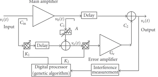
Figure2: Simulation model.
Both conditions must hold along the time and for pos-sible changes due to temperature variations, amplifier bias, and component aging, among others. Several articles and patents have been published relating to correction schemes designed to maintain the amplitude and phase balances over time and temperature [22–32]. The idea of the correction method presented in this paper is to introduce two complex coefficients, one in each loop of the feedback structure, to compensate for the amplitude and phase imbalances. In the practice, these coefficients will be vector modulators. The out-of-band distortion information is used to obtain the optimal values of these coefficients by means of a genetic algorithm.
3. Correction Method Model
A schematic diagram of the simulation model is depicted in
Figure 2. Both complex coefficientsK1andK2are introduced
in the Feedforward structure to hold a suitable matching between the circuit elements and to meet both conditions from (4). Both coefficients are calculated by means of a genetic algorithm, which uses the out-of-band distortion information. Its aim is to reduce the distortion in the output signal, maintaining the output mean power.
The most usually proposed correction schemes [22–32] are based on three generic adaptation techniques: the use of pilot signals inserted at various points in the circuit, methods based on adjustments to minimize the power at critical points in the circuit, and a gradient signal to drive the adaptation with additional circuitry. The pilot signal detection methods are based on introducing, previously to the main amplifier, a pilot signal, with the same frequency as the third-order intermodulation products. The control system tries to cancel this pilot signal; so simultaneously the intermodulation products are also cancelled. The idea is good for a narrowband system, but it is not the better method for a wideband system. The power minimization techniques minimize the distortion components of the output signal. All those detection architectures are basically designed to the reduction of the distortion components from the output signal. The proposed method is based on this last scheme, with the idea of introducing two vector modulators, one in each loop of the Feedforward scheme, to compensate for
the amplitude and phase imbalances minimizing the out-of-band distortion. It is assumed that the complex coefficient for the vector modulator in the first loop isK1and in the second
loop isK2. The computation of these coefficients is achieved
by means of a genetic algorithm whose aim is to reduce the out-of-band distortion. The proposed system requires only a process of downconversion to an intermediate frequency (IF) and two RF power detectors, including filtering, one to measure the output signal power and the other one for the out-of-band signal. Respect to other optimization methods, the optimization techniques based on gradient attempt to estimate the gradient of the error surface and proceed to an optimum solution by following the negative direction of this estimated vector. These algorithms are well known, widely used, proven simple, and effective, but one of their problems is that gradient descent is a local optimization technique, which is limited because it is unable to converge to the global optimum on a multimodal error surface if the algorithm is not initialized in the basin of attraction of the global optimum. It will be a drawback in the presented model, because the proposed fitness function contains several local minima. If a local minimum is reached and it does not fulfil the function fitness condition, the algorithm does not probably converge. Besides, the derivatives of the objective function related to all variables have to be estimated, and so it implies a higher computational load.
4. Genetic Algorithms
Genetic algorithms are stochastic search procedures mod-elled on the Darwinian concepts of natural selection and evolution. In genetic algorithms a set or population of potential solutions is caused to evolve toward a global optimal solution that occurs as a result of pressure exerted by a fitness-weighted selection process and exploration of the solution space. The most important concepts of the genetic algorithms are summarized [34,35].
(i) Gene: is a coded representation of individual opti-mization parameter. A string of genes is called a chromosome.
(iii) Generation is the iterations in the genetic algorithm optimization.
(iv) Parents are the members of the current generation. (v) Children are the members of the next generation.
They are generated by application of simple stochas-tic operators, such as crossover, and mutation. (vi) Fitness: the objective function defining the
optimiza-tion goal, called a fitness funcoptimiza-tion, is a means of assigning a value to each individual in the population. The fitness function assigns to an individual a number representing a measure of the goodness. The proposed genetic algorithm is comprised of the following steps.
(1) Encode the solution parameters as genes.
(2) Create a string of the genes to form a chromosome (member).
(3) Initialize a starting population by creatingN mem-bers by a randomised manner.
(4) Evaluate and assign fitness values to each member in the population.
(5) Convergence test. Stop if the termination criterion is met.
(6) Else, generate new population, called children, by recombination and mutation selecting some (M) members of the current population, called parents. (7) Loop to the step 4 and repeat for a new population. The selection procedure introduces the influence of the fitness function to the genetic algorithm optimization process. The fitness function is the measure of the goodness of a member of the population. Selection cannot be based only on choosing the best member of the population because it may not be very close to the optimal solution. Different types of selection strategies have been developed and used for genetic algorithm optimisation. Several of the more important and most widely used of these selection strategies are as follows.
Population Decimation. Members are ranked according to their fitness values from the largest to the smallest. A minimum fitness is chosen as a cut-off point and any member with a lower fitness than the minimum is removed from the population. The remaining members are used to produce the new generation. The advantage of this technique is its simplicity, and the disadvantage is that once a member has been removed from the population, any characteristic of that member is lost.
Proportionate Selection. The probability of selecting a mem-ber from the population is a function of the relative fitness of the member. Members with high fitness will participate in the production of the next generation more often than less fit members.
Tournament Selection. In this technique a subpopulation of
Kindividuals is chosen at random from the population. The member in the subpopulation with the highest fitness wins the tournament and becomes the selected member. All of the subpopulation members are then placed back into the general population and the process is repeated.
Once a pair of members has been selected as parents, a pair of children is created by recombining and mutating of the parents using the basic genetic algorithm operators, crossover and mutation. The crossover operator accepts the parents and generates two children. The effect of crossover is to rearrange the genes with the objective of producing better combinations of genes. The mutation operator provides a means for exploring portions of the solution surface that are not represented in the genetic makeup of the current population.
5. Results
The source signal for simulations was an OFDM signal, similar to the DVB-T standard signal [2], with the following parameters:
(i) 2K mode:1705 active subcarriers, (ii) subcarrier spacing: 4.464 kHz,
(iii) useful symbol duration: 224 microseconds, (iv) constellation: 16 QAM.
The modulated OFDM signal during a symbol can be expressed as follows:
s(t)=Re ⎧ ⎨ ⎩ej2π fct
Kmax
k=Kmin ci,kej2πk
(t−Δ)/Tu
⎫ ⎬
⎭ (5)
with k = k−(Kmax +Kmin)/2. Tu is the inverse of the
carrier spacing, is the duration of the guard interval, k
denotes the carrier number, fc is the central frequency of
the RF signal, and ci,k is a complex symbol for the carrier
k. There is a clear resemblance between (5) and the inverse Discrete Fourier Transform (DFT). Since various efficient Fast Fourier Transform algorithms exist to perform the DFT and its inverse, it is a convenient form of implementation to use the inverse FFT (IFFT) in a DVB-T modulator to generate N samples corresponding to the useful part, Tu
long, of each symbol. The guard interval is added by taking copies of the last NΔ/Tu of these samples and appending
them in front. This process is then repeated for each symbol in turn, producing a continuous stream of samples, which constitutes a complex baseband representation of the DVB-T signal. A subsequent up-conversion process then gives the real signals(t)centered on the frequency,fc.
without errors, including the appropriate filtering stage in the digital signal processor. All results are obtained by means of simulation using the MATLAB software.
5.1. Genetic Parameters
5.1.1. Fitness Function. The proposed fitness function is defined to reduce the out-of-band spurious emission. The fitness function compares individual performance given by the interference measurement with the desired performance. The fitness function returns a value to the genetic algorithm that is in some manner proportional to its goodness.
Due to the coexistence of many digital and analog broad-cast signals in the whole service bandwidth, the requirements with respect to the spectrum level outside the channel bandwidth are determinated in the standard DVB-T through spectrum emission templates [2]. For example, the spectrum level at frequency offset of 3.8 MHz and 4.25 MHz from the center frequency must be at least −32.8 dB and −66.9 dB lower than the center spectrum, respectively (power level measured in a 4 kHz bandwidth).
Thus, a desired performance for the spectrum level is to obtain an interference measurement at frequency offset of 4.25 MHz less than−67 dB (assuming 0 dB corresponds to the total output power), assuring an output signal mean power of 10±5% Watts. This output power requirement has been included in the fitness function to get, in addition to spectrum efficiency, also power efficiency. This is an impor-tant advantage of the proposed method regarding other linearization techniques, where the linearity is obtained by means of an Output Power Backoff, reducing the power efficiency. Moreover, with the proposed fitness function, a distortion measurement at frequency offset of 3.8 MHz less than –32.8 dB is also obtained. The convergence criteria used to stop the genetic algorithm are that any member of the population reaches an interference measurement at 4.25 MHz offset less or equal than –67 dBc, ensuring an output mean power of 10 Watts (±5%). If it does not occur, the GA stops when the number of iterations is higher than 20; in this case, it is considered that the genetic algorithm has not converged, and the best calculated solution is selected. The evaluation process of the fitness function is described in
Figure 3.
5.1.2. Coding. Genetic algorithms operate on a coding of the parameters instead of the parameters themselves. The coding is a mapping from the parameter space to the chromosome space that transforms the set of parameters, usually numbers, to a finite length string. In the proposed method, the parameters simulate the complex coefficients K1 and K2.
Both, real and imaginary, parts are coded by a binary coding. The genetic algorithm optimisation operates on the coded form of the parameters, but the fitness function is calculated with the decoded parameters. In the binary decoding process is necessary to define the minimum and maximum range bounds of the coefficientsK1 andK2, and it determinates
the range bounds of imbalances between circuit elements to be corrected by the proposed method inFigure 2. Another
important parameter is the number of bits for the binary coding. Figure 4shows the minimum reached interference value, measured at frequency offset of 4.25 MHz, for several amplitude and phase errors between circuit elements, when
K1andK2are coded with 16, 32, and 48 bits for each one.
It can be seen that the proposed correction method using a codification of 32 bits is enough to meet the desired specifications regarding out-of-band distortion reduction, assuming errors between circuit elements among ±1.5 dB and ±3o. A codification of 16 bits is also possible but with a lower probability of convergence and a higher value in the number of codification bits does not provide any improvement, only a higher computational load.
5.1.3. Selection Technique. Another important choice is the selection technique of the genetic algorithm. Figure 5
compares the histogram taking into account the iteration of convergence as the quality factor for the three above-mentioned selection techniques. It can be seen that the best selection strategy for the presented problem is the population decimate technique and this will be the used selection method in the following presented results.
5.1.4. Genetic Operators. A research for typical genetic algo-rithm parameters, crossover and mutation among others, has been also carried out in order to find the optimal value for each one.
Threshold (Parents Size). This parameter defines the number of parents used in the next generation. It is a very important parameter in the convergence speed of the genetic algorithm.
Figure 6 shows the finalization iteration of the algorithm
and the obtained distortion reduction depending on the threshold parameter. It can be seen that a low value in this parameter implies generally a faster convergence and higher interference reduction, but if the value is too low, convergence problems could appear. Thus, a threshold value close to 0.25 is chosen.
Crossover. This operator redistributes the characteristics of a pair of parents to create a new population member. The new member contains elements from both parents depending on the crossover probability. Figure 7 shows the iteration of convergence of the genetic algorithm and the obtained distortion reduction depending on the crossover operator. Typically high probability values have been found to work best in most situations. In this case, a probability value of 1 is chosen by simplicity in the implementation.
Genetic algorithm process iteration=
Iteration + 1
Iteration>
Max Iteration?
Pout Measurement output mean Power
=PoutNOM±5% W?
Measurement interference (at BW offset)
<InterferenceMAX?
Finish Yes
Yes
Yes No
No
No
Figure3: Evaluation process of the fitness function (Max Iteration=20, PoutNOM=10 Watts, BW Offset=4.25 MHz, InterferenceMAX=
−67 dBc ).
Table1: Convergence probability of the proposed genetic algorithm and its iteration of convergence (on average and standard deviation) for several population sizes.
Population size 25 40 60 80
Convergence probability (%) 89.6 96.5 100 100
Iteration of convergence On average 11.2 6.03 3.91 3.2
Standard Deviation 4.21 2.9 1.86 1.81
A high population size implies not only a less number of iterations for the genetic algorithm convergence, but also a longer computational and evaluation time and higher computational load. Table 1 shows the obtained results in 1000 trials for several population sizes regarding convergence probability of the GA, iteration of convergence (on average) and its standard deviation. It can be seen that a low population size decreases the convergence probability. There-fore, according to simulations, a trade-offsolution between convergence and computation for this parameter can be 60.
Thus, the following results presented in this paper have been obtained using the next parameters:
(i) population decimate selection, (ii) population sizeN = 60, (iii) parents sizeM = 16,
−95
−90
−85
−80
−75
−70
−65
−60
In
te
rf
er
enc
e
measur
ement
(dBc)
−2 −1.5 −1 0.5 0 0.5 1 1.5 2
Amplitude imbalance Phase 3◦, 16 bits
Phase 3◦, 32 bits Phase 3◦, 48 bits
Phase 0◦, 16 bits Phase 0◦, 32 bits Phase 0◦, 48 bits
Figure4: Interference measurement (at 4.25 MHz frequency offset of the centre frequency) reached applying the proposed correction method for several amplitude and phase imbalances between circuit elements whenK1andK2are coded with 16, 32, and 48 bits.
5.2. Transmit Signal Power Spectrum Performance. Figure 9
shows the normalized power spectral density (PSD) of the output power amplifier signal with and without the proposed correction method for each iteration. It shows the genetic algorithm adaptation in function of the number of iterations for a simulation in short, where the iteration of convergence is 3. The interference measurement at a 4.25 MHz frequency offset without correction is around –35 dBc, but applying the proposed method an interference measurement less than – 70 dBc is reached in a few iterations. Simulation conditions are a 1 dB amplitude imbalance and a 3◦ phase imbalance between circuit elements (corresponding to all couplers of the two loops) and 10 Watts output mean power, for a 16-QAM modulated OFDM input signal.
5.3. Error Vector Magnitude. The Error Vector Magnitude (EVM) is another important measurement in digital com-munication systems, which is more focused on modulation quality and performed on the received signal. EVM is defined in [36] as
EVM=
1/NNj=1
δI2+δQ2
S2 max
×100%, (6)
whereIandQare the ideal coordinates of the constellation points,δIandδQare the errors at the received points,Nis the number of received points of the constellation, andSmax
is the magnitude of the vector to the outermost state of the constellation. The difference between the position of thejth received symbol and the ideal one is the cause of nonnull values ofδI,δQ, and EVM.
0 5 10 15 20 25
Oc
cur
renc
es
(%)
1 2 3 4 5 6 7 8 9 10 11 12 13 14 15 16 17 Iteration of convergence
Tournament selection Proportionate selection Population decimation
Figure5: Histogram of the number of occurrences regarding the iteration of convergence for three different selection techniques: population decimation, proportionate, and tournament selection with the following parameters: Populate N = 60, Subpopulate (for tournament selection)= 4, Parents sizeM = 16, crossover probability= 1, and mutation probability= 0.05.
5 6 7 8 9 10 11
It
er
at
ion
o
f
con
ve
rgenc
e
0 0.1 0.2 0.3 0.4 0.5 0.6 0.7 0.830 35 40 45 50 55 60
Im
pr
o
vement
in
the
dist
o
rt
ion
reduction
(dB)
Threshold probability Iteration of convergence Distortion reduction
Figure 6: Iteration of convergence of the genetic algorithm and the obtained distortion reduction in function of the threshold parameter.
3 4 5 6 7 8 9 It er at ion o f con ve rgenc e
0.2 0.4 0.6 0.8 1 1.246 46.5 47 47.5 48 48.5 49 49.5
Im pr o vement in the dist o rt ion reduction (dB) Crossover probability Iteration of convergence Distortion reduction
Figure 7: Iteration of convergence of the genetic algorithm and the obtained distortion reduction in function of the crossover probability. 0 5 10 15 20 25 30 It er at ion o f con ve rgenc e
0 0.1 0.2 0.3 0.4 0.5 0.6 0.7 0.810 20 30 40 50 60 Im pr o vement in the dist o rt ion reduction (dB) Mutation probability Iteration of convergence Distortion reduction
Figure 8: Iteration of convergence of the genetic algorithm and the obtained distortion reduction in function of the mutation probability.
The vector error requirement can be also included in the fitness function; therefore, besides an interference value less than –67 dBc, the EVM has to be less than a threshold value. The inclusion of an EVM condition (<5%) in the fitness function has been tested and the results have not changed, because this condition fulfil always. Moreover, it does not imply any improvement respect to reduction in the number of iterations, but it supposes an increase in the computational complexity and in the additional circuitry to demodulate the signal. −100 −90 −80 −70 −60 −50 −40 −30 −20 −10 0 No rm al iz ed p o w er sp ec tr al d en si ty (d B )
−15 −10 −5 0 5 10 15
Offset from centre frequency (MHz) Iteration 1
Iteration 2
Iteration 3
Without correction With correction
Figure9: Normalized Power Spectral Density of the output signal using a Feedforward scheme with and without the proposed distortion cancellation method for each iteration of the GA.
5.4. Delay. In a Feedforward scheme, signals traveling through an amplifier have an associated group delay due to the transit time through the semiconductors and the delay through matching and interconnection networks. It is necessary to introduce compensating time delay elements into both loops. Even if the amplitude and phase are perfectly adjusted in both loops, a delay difference between the upper and lower branches of a cancellation circuit causes a reduction of the effective bandwidth. Besides, a delay mismatch also causes an increase in the out-of-band distortion [37,38].
A null loop delay has been assumed in the previous simu-lations. Accurate delay matching is important to improve the performance of this method, but it is not a limitation when implementing it in a real system. First, a fixed-delay value can be calculated to reduce the group delays of both loops as it is presented in [39], and then adaptive delay circuits can be devised for situations in which operating conditions produce delay variations in excess.
6. Conclusion
−1.5
−1
−0.5 0 0.5 1 1.5
−1.5 −1 −0.5 0 0.5 1 1.5
Q
I
(a)
−1.5
−1
−0.5 0 0.5 1 1.5
−1.5 −1 −0.5 0 0.5 1 1.5
Q
I
(b)
Figure10: Received signal constellation diagram (normalized): (a) without and (b) with the proposed linearization method.
are calculated by means of a genetic algorithm. A full study is carried out to obtain the optimal values of the genetic algorithm parameters for wideband wireless OFDM systems. Using a simulation procedure we have shown that the method converges in a few iterations towards very low interference levels in out-of-band channels improving also the vector error measurement. The proposed method implies a very simple architecture and easy practical implementation. This method could be implemented in a real system by means of suitable commercial devices.
Acknowledgments
This work has been financed by the Spanish Govern-ment (Project TEC2008-06684-C03-02/TEC from MICINN and FEDER), Gobierno de Arag ´on (Project PI003/08 and WALQA Technology Park), and the European IST Project EUWB
References
[1] ETSI EN 300 401, “Radio broadcasting systems; digital audio broadcasting (DAB) to mobile, portable and fixed receivers,” v1.3.3 (2001-05).
[2] ESTI EN 300 744—Digital Video Broadcasting (DVB), “Fram-ing structure, channel cod“Fram-ing and modulation for digital terrestrial television,” v1.4.1 (2001-01).
[3] ETSI EN 302 304—Digital Video Broadcasting (DVB), “Transmission System for Handheld Terminals (DVB-H),” v1.1.1 (2004-11).
[4] R. van Nee and R. Prasad, OFDM for Wireless Multimedia
Communications, Artech House, Boston, Mass, USA, 2000.
[5] P. Banelli, G. Baruffa, and S. Cacopardi, “Effects of HPA non linearity on frequency multiplexed OFDM signals,”IEEE
Transactions on Broadcasting, vol. 47, no. 2, pp. 123–136, 2001.
[6] A. Chini, Y. Wu, M. El-Tanany, and S. Mahmoud, “Hardware nonlinearities in digital tv broadcasting using ofdm modula-tion,”IEEE Transactions on Broadcasting, vol. 44, no. 1, pp. 12– 21, 1998.
[7] E. Costa, M. Midrio, and S. Pupolin, “Impact of amplifier nonlinearities on OFDM transmission system performance,”
IEEE Communications Letters, vol. 3, no. 2, pp. 37–39, 1999.
[8] M. Helaoui, S. Boumaiza, A. Ghazel, and F. M. Ghannouchi, “On the RF/DSP design for efficiency of OFDM transmitters,”
IEEE Transactions on Microwave Theory and Techniques, vol.
53, no. 7, pp. 2355–2361, 2005.
[9] L. Ding, G. T. Zhou, D. R. Morgan, et al., “A robust digital baseband predistorter constructed using memory polynomi-als,”IEEE Transactions on Communications, vol. 52, no. 1, pp. 159–165, 2004.
[10] P. Banelli and G. Baruffa, “Mixed BB-IF predistortion of OFDM signals in non-linear channels,”IEEE Transactions on
Broadcasting, vol. 47, no. 2, pp. 137–146, 2001.
[11] A. N. D’Andrea, V. Lottici, and R. Reggiannini, “Nonlinear predistortion of OFDM signals over frequency-selective fading channels,”IEEE Transactions on Communications, vol. 49, no. 5, pp. 837–843, 2001.
[12] H. W. Kang, Y. S. Cho, and D. H. Youn, “On compensating nonlinear distortions of an OFDM system using an efficient adaptive predistorter,”IEEE Transactions on Communications, vol. 47, no. 4, pp. 522–526, 1999.
[13] L. Ding, G. T. Zhou, D. R. Morgan, et al., “A robust digital baseband predistorter constructed using memory polynomi-als,”IEEE Transactions on Communications, vol. 52, no. 1, pp. 159–165, 2004.
[14] T. Liu, S. Boumaiza, and F. M. Ghannouchi, “Augmented Hammerstein predistorter for linearization of broadband wireless transmitters,”IEEE Transactions on Microwave Theory
and Techniques, vol. 54, no. 6, pp. 1340–1349, 2006.
[15] H. Zhi-yong, G. Jian-hua, G. Shu-jian, and W. Gang, “An improved look-up table predistortion technique for HPA with memory effects in OFDM systems,” IEEE Transactions on
[16] M. Helaoui, S. Boumaiza, A. Ghazel, and F. M. Ghannouchi, “Power and efficiency enhancement of 3G multicarrier amplifiers using digital signal processing with experimental validation,” IEEE Transactions on Microwave Theory and
Techniques, vol. 54, no. 4, pp. 1396–1403, 2006.
[17] M.-C. Chiu, C.-H. Zeng, and M.-C. Liu, “Predistorter based on frequency domain estimation for compensation of non-linear distortion in OFDM systems,” IEEE Transactions on
Vehicular Technology, vol. 57, no. 2, pp. 882–892, 2008.
[18] J. Kim, Y. Y. Woo, J. Moon, and B. Kim, “A new wideband adaptive digital predistortion technique employing feedback linearization,” IEEE Transactions on Microwave Theory and
Techniques, vol. 56, no. 2, pp. 385–392, 2008.
[19] P. L. Gilabert, A. Cesari, G. Montoro, E. Bertran, and J.-M. Dilhac, “Multi-lookup table FPGA implementation of an adaptive digital predistorter for linearizing RF power ampli-fiers with memory effects,”IEEE Transactions on Microwave
Theory and Techniques, vol. 56, no. 2, pp. 372–384, 2008.
[20] P. Garc´ıa, A. Ortega, J. De Mingo, and A. Valdovinos, “Nonlinear distortion cancellation using LINC transmitters in OFDM systems,”IEEE Transactions on Broadcasting, vol. 51, no. 1, pp. 84–92, 2005.
[21] P. B. Kenington,High-Linearity RF Amplifier Design, Artech House, Boston, Mass, USA, 2000.
[22] A. J. Zozaya, E. B. Alberti, and J. Berenguer-Sau, “Adap-tive feedforward amplifier linearizer using analog circuitry,”
Microwave Journal, vol. 44, no. 7, pp. 102–114, 2001.
[23] M. G. Obermann and J. F. Long, “Feed Forward Distortion Minimization Circuit,” U.S., Patent 5, 077,532, December, 1991.
[24] S. Narahashi and T. Nojima, “Extremely low-distortion multi-carrier amplifier–Self-adjusting feed-forward (SAFF) ampli-fier,” in Proceedings of IEEE International Communication
Conference, vol. 3, pp. 1485–1490, June 1991.
[25] P. B. Kenington, M. A. Beach, A. Bateman, and J. P. Mcgeehan, “Apparatus and Method for Reducing Distortion in Amplifi-cation,” U.S., Patent 5, 334,946, August, 1994.
[26] J. K. Cavers, “Adaptation behaviour of a feedforward amplifier linearizer,”IEEE Transactions on Vehicular Technology, vol. 44, no. 1, pp. 31–39, 1995.
[27] R. M. Bauman, “Adaptive Feed-Forward System,” U.S. Patent 4, 389,618, June, 1993.
[28] T. E. Olver, “Adaptive Feedforward Cancellation Technique that is Effective in Reducing Amplifier Harmonic Distortion Products as well as Intermodulation Distortion Products,” U.S. Patent 4, 560, 945, December 1985.
[29] S. J. Grant, A DSP controlled adaptive feedforward power
amplifier linearizer, M.S. thesis, School of Engineering Science,
Simon Frasier University, Burnaby, Canada, July 1996. [30] Y. Wang, J. D. Fredrick, and T. Itoh, “A novel DSP
archi-tecture of adaptive feedforward linealizer for RF amplifiers,”
in Proceedings of the IEEE MTT-S International Microwave
Symposium, vol. 2, pp. 805–808, May 2001.
[31] Y. Chen, B. P. Ng, and A. C. Kot, “Adaptive algorithms for feedforward power amplifier linearizer,” inProceedings of the
IEEE MTT-S International Microwave Symposium, vol. 1, pp.
485–488, June 2000.
[32] Y. Y. Woo, Y. Yang, J. Yi, J. Nam, J. Cha, and B. Kim, “An adaptive feedforward amplifier for WCDMA base stations using imperfect signal cancellation,”Microwave Journal, vol. 46, no. 4, pp. 22–44, 2003.
[33] P. Garc´ıa-Ducar, J. De Mingo, and A. Valdovinos, “Misalign-ments feedforward transmitter correction design for nonlinear distortion cancellation in OFDM systems,” inProceedings of
the IEEE Vehicular Technology Conference (VTC ’06), pp. 847–
851, 2006.
[34] Y. Rahmat-Samii and E. Michielssen,Electromagnetic
Optimi-sation by Genetic Algorithms, John Wiley & sons, New York,
NY, USA, 1999.
[35] D. E. Goldberg,Genetic Algorithms in Search, Optimization and
Machine Learning, Kluwer Academic Publishers, Boston, Mass,
USA, 1989.
[36] ETSI TR 101 290—Digital Video Broadcasting (DVB), “Mea-surement Guidelines for DVB Systems,” v. 1.2.1, May 2001. [37] A. J. Zozaya and E. Bertran, “On the performance of cartesian
feedback and feedforward linearization structures operating at 28 GHz,”IEEE Transactions on Broadcasting, vol. 50, no. 4, pp. 382–389, 2004.
[38] K. J. Parsons and P. B. Kenington, “Effect of delay mismatch on a feedforward amplifier,”IEE Proceedings: Circuits, Devices
and Systems, vol. 141, no. 2, pp. 140–144, 1994.
[39] J. Legarda,Feedforward Amplifiers for Wideband