IJEDR1603140
International Journal of Engineering Development and Research (www.ijedr.org)862
Design and Implementation of Inverter for PV array
feeding AC Grid
1Bhawna Sahu, 2Prasant Kumar Jena, 3Bhuvnesh Rathore
1Student, RCET Bhilai, 2Asst. Prof. RCET Bhilai, 3Student, Govt. Engg. College Bikaner
Abstract - Photovoltaic electricity generators directly converts solar radiation in to electrical energy and having a lots of various significant advantages such as being silent and inexhaustible, no rotationary parts available, pollute free and size independent and higher electrical conversion efficiency. By Solar photovoltaic devices increasing various anti-pollution apparatus and penetration can be operated by solar PV power; such as, water filtration by electrochemical processing or controlling desert expansion by PV water pumping process with tree implantation. However, the power induced in output by photovoltaic array is influenced by the solar radiation intensity and temperature of this solar panel. Therefore, to improve the efficiency of the proposed renewable energy system, it’s necessary to tracking the maximum power point (MPP) of the input source. In this, Perturb & Observe maximum power point tracking algorithm is used to maximize energy conversion efficiency. In this project, The control and design issues of proposed associated system with the development of three phase grid connected photovoltaic array system inverter are describe in this project. This proposed system consists of a switching mode of DC-DC boost converter and an inverter. The switching techniques of proposed system, inverter pulse control by fuzzy logic controller with grid synchronization condition. The performances of the proposed inverter are simulated under grid-connected scenario using MATLAB. Simulation result of using fuzzy logic controller shows the minimize voltage THD level.
Index Terms -.PV array, boost converter, inverter, MATLAB.
I.INTRODUCTION
The ordinary fossil fuel or non-renewable energy sources, for example, petroleum, regular gas, and coal which is utilized for generation of the power. After the burning of such fuel bringing on different worldwide issues, for example, an unnatural wea ther change and green house impact and make contamination which is exceptionally harmful for human and unsafe for the whole existence of our planet. The renewable energy sources or non-conventional sources (sun based, wind, tidal, ocean, geothermal and so on.) Among the renewable energy sources, the solar energy has been generally utilized as a part of low power applications. Solar energy which depends on photovoltaic (PV) array, Solar energy which is based on photovoltaic (PV) effect, is also the most promising candidate for research and development for large scale users as the fabrication of minimum cost PV device turns into a reality. Photovoltaic generators which directly change over sun based radiation into power have a great deal of huge points of interest, for example, being inexhaustible and pollution free, quiet, with no rotating parts, and with size independent electric transformation proficiency. Because of safe ecological impact of PV generators, they are useful for power produced by other different ways and considerably better known for power generator where none was available some time recently. With expanding penetration of sun based photovoltaic device, different anti-pollution apparatus device can be worked by sunlight based PV power; for instance, water refinement by electrochemical handling or ceasing desert development by PV water pumping with tree implantation.
Fig 1 Sources of Energy
IJEDR1603140
International Journal of Engineering Development and Research (www.ijedr.org)863
impact. It conserves non-renewable energy sources, reduces environmental damage caused by exploration and extraction of fossil fuels, and reducing exposure of people and wildlife to large energy production plants. A renewable energy system converts the energy found from sunlight, wind, falling-water, sea-waves (tides), geothermal heat, or biomass into a form, we can use such as electricity or heat. The vast majority of the renewable energy comes either by implication or straightforwardly from sun and wind and it can never be depleted, and along these lines they are called renewable.II.METHODOLOGY
Diode model of photovoltaic cell
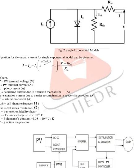
Fig .2 shows two electrical equivalent models of PV cell derived from the physical mechanism of PV cell. The first model contains two diodes that reflect diffusion and carrier recombination. The second model is a simplified providing similar characteristic for the representation of PV cell.
Fig .2 Single Exponential Models Equation for the output current for single exponential model can be given as:
( )
0
1
se q V IR
kT se
L
sh
V
IR
I
I
I
e
R
1Where,
V = PV terminal voltage (V) I = PV terminal current (A) IL = photocurrent (A)
I1 = saturation current due to diffusion mechanism (A)
I2 =saturation current due to carrier recombination in space charge region (A) Io = saturation current (A)
Rsh = cell shunt resistance (
) Rse = cell series resistance (
) ɳ = p-n junction ideality factor q = electronic charge =1.6 × 10⁻¹⁹ Ck = Boltzmann’s constant =1.38 × 10⁻²³ J / K T = junction temperature
IJEDR1603140
International Journal of Engineering Development and Research (www.ijedr.org)864
MPPT TechniquesPV module has a maximum power point for a given temperature and insolation. If a load line crosses this point, maximum power would be transferred to the load. When temperature/insulation changes, maximum power point changes. Since the load line does not change, it does not pass through the maximum power point and hence maximum power cannot be transferred to the load]. To achieve the transfer of maximum power, it requires that the load follows the maximum power point and this is achieved by translating the actual load line point to maximum power point by varying the duty cycle of DC-DC converter. The duty cycle can be varying throughout the day to track the maximum power point automatically. There are various techniques which adjust duty cycle (D) automatically which can be implemented in analog or digital method.
There are different techniques used to track the maximum power point. Few of the most popular techniques are: 1) Perturb and Observe
2) Incremental Conductance method 3) Fractional short circuit current 4) Fractional open circuit voltage 5) Neural networks
6) Fuzzy logic
Perturb and Observe Algorithm:
Perturb and Observe Method is a standout amongst the most broadly usable method. Because of its less complex implementation effort, this method is preferred over other. In this project, P and O are used for MPPT considering this as a traditional strategy. Perturb and Observe is most broadly utilized MPPT technique. It depends on Hill Climbing idea of following. From the P-V characteristics of solar array the power increments with voltage up to MPPT and afterward control diminishes as voltage increments further. Hence, expanding the voltage builds the power when working point is on the left of MPP and diminishes the power when working point is on the right of MPP. The controller changes and adjust the voltage by a little sum from the array and measures power; if the power expands, then further modification in that direction are tried until power no longer increases. Hill climbing system includes a bother in obligation cycle .While P&O strategy includes the perturbation in working voltage of PV array.
Perturb and Observe presents an initial perturbation in the voltage by changing duty cycle of converter and then observations are made by utilizing detecting hardware. P&O algorithm uses current and voltage measurements to calculate change in power ∆P over a change in time and change in the duty cycle ∆D of the signal sent to the gate of the switch (MOSFET) in the boost converter. Given that ∆P and ∆D can be each either negative or positive, so there are four cases in this. To determine whether the duty cycle of gate signal varies it should be increased or decreased.
The block flow of the technique is given in Fig 4.
Fig.4 Flow Block of P&O algorithm
The time complexity of this algorithm is very less but on reaching very close to the maximum power point (MPP) it doesn’t stop at the MPP and keeps on perturbing on both directions. When it happens the algorithm has reached very close to the MPP and we can set an appropriate error limit or can use a wait function which ends up increasing the time complexity of the algorithm. However this method does not take account of the rapid change of solar irradiation level (due to which MPPT changes) and considers it as a change in MPP due to perturbations and ends up calculating the wrong MPP. To avoid this problems use incremental conductance method.
IJEDR1603140
International Journal of Engineering Development and Research (www.ijedr.org)865
Inverter pulse controlled by fuzzy logicFuzzy logic uses fuzzy sets of theory, in which having a variable member of one or more sets, with a specified degree of membership. Fuzzy logic allows us to emulate the human imprecise data, make decision based on vague reasoning process in computers, quantify imprecise information, and in complete resistive load is connected to the grid module through the dc-ac converter.The Fuzzy logic controller uses the fuzzy logics or sets to make the decisions and to control the output of the controller. The main components in fuzzy logic based pulse controller are fuzzification, rule-base inference and defuzzification as shown in fig 1.6.
Fig .5 General diagram of a fuzzy controller
There are two inputs in to the controller – error e(k) and change in error Δe(k). The Fuzzification block converts the crisp inputs to fuzzy inputs. The rules are formed in rule base in form of membership function and are applied in inference block. The defuzzification converts the fuzzy output to the crisp output. The fuzzy inference (membership function) is carried out by using Mamdani’s method, and the defuzzification uses the centre of gravity to compute the output of this FLC which is the change in duty cycle.
e(k) = p(k)-p(k-1)/v(K)-v(K-1) ∆e(k) = e(k)-e(k-1)
a) Fuzzification
The fuzzification is the process to converting the crisp set into linguistic fuzzy sets using fuzzy membership function. The membership function is a curvature that describes each point of membership value in the input space. Variables are assigned as mf1int1, mf2int1, mf3int1, mf4int1, mf5int1, mf6int1, mf7int1. The inputs of fuzzification are the error and change in error. The value of input error e(k) and change in error e(k-1) are normalized by an input scaling factor. The input scaling factor has been designed such that input values are between -0.5 and 18. Membership functions have many structures; among those bell shape memberships function is used because for any particular input there is only one dominant fuzzy subset. Fuzzy rule base is the basic function of fuzzification.
b) Inference Engine
Fuzzy inference block is an working method that formulates a logical decision which is membership function based on the fuzzy rule setting and transforms the fuzzy rule base inputs into fuzzy linguistic output. Fuzzy linguistic descriptions are formal representations of systems made through fuzzy IF-THEN rules. They encode knowledge about a system in statements of the form: IF (a set of conditions) are satisfied THEN (a set of consequents) can be inferred.
c) Defuzzification
The final step in the FLC process is the defuzzification.In these will have a number of rules that converts to a number of variables into a fuzzy result, that is, the result is described in terms of membership in fuzzy sets. The Centre of Gravity defuzzification method is used. The inputs to the Fuzzy controller are change in inverter error and change in inverter output error corresponding to the two sampling time instants. The two inputs are processed by the Fuzzy controller and the output of the Fuzzy controller is the incremental reference voltage (ΔVref). This output is given to the gate pulse of inverter power. The first input variable (ΔP) for the fuzzy logic controller is divided into seven Fuzzy sets: PB (Positive Big), PM (Positive Medium), PS (Positive Small), ZZ (Zero), NS (Negative Small), NM (Negative Medium) and NB (Negative Big). The second input variable (ΔI) for the fuzzy logic controller is also divided into7 Fuzzy sets: : PB (Positive Big), PM (Positive Medium), PS (Positive Small), ZZ (Zero), NS (Negative Small), NM (Negative Medium) and NB (Negative Big). The only one output variable (ΔIref) is divided into 7 Fuzzy sets: PB (Positive Big), PM (Positive Medium), PS (Positive Small), ZZ (Zero), NB (Negative Big), NM (Negative Medium) and NS (Negative Small). The rules are formed as shown in table 1.1 and 1.2.
e\Δe N Z P
NB B B B
NM M M M
NS S B B
IJEDR1603140
International Journal of Engineering Development and Research (www.ijedr.org)866
PS S B B
PM M M M
PB B B B
Table 1.1 rulesfor FUZZY controller for kp
e\Δe N Z P
NB Z Z Z
NM S S M
NS M M B
Z B B B
PS M M B
PM S S M
PB Z Z Z
Table 1.2 rulesfor FUZZY controller for ki
Fuzzy-tuned PI controller analysis for current control
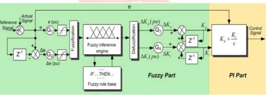
The synoptic block diagram of the proposed fuzzy-tuned PI controller is illustrated in figure 6. As inputs to the fuzzy-tuned PI current controller are the actual and the reference currents. The current controller outputs the appropriate reference signal (reference voltage). The reference voltage in α-β reference frame will be used by the Space Vector Modulation algorithm for the switching pattern generation.
Fig.6 General Structure of the fuzzy-tuned PI controller
The operation of the fuzzy-tuned PI controller is based on the use of a FLC for on-line tuning of the gains Kp and Ki of the PI controller, as shown in equation. Then the PI controller uses the adjusted gains Kp, Ki and the current error (e) to create the reference output control signals (reference voltage).
𝐾𝑃= ∆𝐾𝑃+ 𝐾𝑃(𝑘 − 1)
𝐾𝑖= ∆𝐾𝑖+ 𝐾𝑖(𝑘 − 1)
As inputs to the fuzzy-tuned PI controller the error e = ic,ref - ic and the error variation Δe=e(k)-e(k-1) are determined. As outputs
from the fuzzy part, the gains ΔKi (pu) and ΔKp
IJEDR1603140
International Journal of Engineering Development and Research (www.ijedr.org)867
Input and output blocks of FUZZY logic
In this case, the membership functions are represented by using triangular membership functions. As both inputs have SEVEN subsets, a fuzzy rule base formulated for the present application is given in Table III. The performances of fuzzy logic based gate pulse control are able to generate pulse and fed it to inverter gate.
III.SIMULATION RESULT
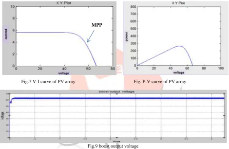
Fig.7 V-I curve of PV array Fig. P-V curve of PV array
Fig.9 boost output voltage
From the output voltage curve of boost converter, it is clarify that before reaching its final value, a time .04s is decreased. In this a small dip in the curve shows the decreasing time, this is the very time consumed in processing the technique of tracking before the maximum power tracking actually starts processing.
IJEDR1603140
International Journal of Engineering Development and Research (www.ijedr.org)868
Fig. 11 Inverter output voltage with R load
Fig. 12 Inverter output current with R load
Fig. 13 Inverter output current with nonlinear load
IJEDR1603140
International Journal of Engineering Development and Research (www.ijedr.org)869
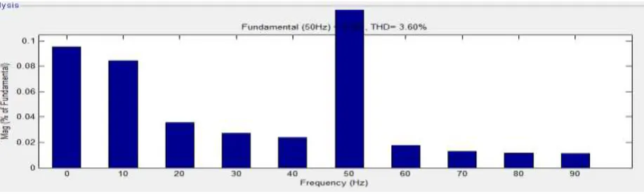
Fig 14 THD of inverter output current with R and Nonlinear load
Fig. 14 is the THD analysis of output voltage of inverter and it is conclude that after using fuzzy logic controller in inverter feeding grid, the output voltage harmonic is zero. This controller technique shows better performance in harmonic reduction comparing other controller.
IV.CONCLUSION AND FUTURE SCOPE
This project has presented an intelligent inverter close loop control strategy of the PV system feeding AC grid using fuzzy logic controller. The MPPT method used here is found to be more efficient and increase the efficiency of pv system. This method is better than other MPPT methods and hence better results are obtained using perturb and observe method. Mainly we uses DC-DC boost converter and for grid DC- AC inverter is used.
The boost converter has advantages that having good output voltage regulation. Thus the boost converter is capable to improving the level of voltage of pv panel. Inverter Fuzzy Pi controller new controller is used to improve efficiency. The simulation results indicate that the proposed grid connected photovoltaic system inverter trace the maximum point of solar array power and then converts it to a high quality ripple free pure sinusoidal ac power with a voltage THD about to less than 5%.
The MPPT method is used in this proposed system can be varied with other different methods and a better efficient tracking can be obtained. The dc voltage controllers used are not of very high efficiency and can be replaced with other types to get a better result .Inverter pulse can be controlled by another other controller.
REFERENCES
[1] David Velasco de la Fuente, Trujillo Rodriguez, Gabriel Ggarcera, Emilio Figueres “Photovoltaic Power System with Battery Backup with Grid Connection”. IEEE Trans. Ind. Electron. vol. 60 no.4 April 2013.
[2] Marcelo G, Gazoli J. and Filho E., “Comprehensive Approach to modeling and Simulation of Photovoltaic Arrays”, IEEE Trans. Power Electron. Vol. 24, No. 5, May 2009, .
[3] Esram T. and Chapman P., “Comparison of Photovoltaic Array Maximum Power Point Tracking Techniques”, IEEE Trans.
Energy Convers. Vol. 22, No. 2, June 2007.
[4] W. Xiao, N. Ozog, W. G. Dunford. “Topology study of photovoltaic interface for maximum power point tracking,” IEEE
Trans. Power Electron. Vol. 54, No. 3, pp. 1696-1704, 2007. A 200W MPPT Boost Converter for BIPV Applications with Integrated Controller Yi-Hsiang Wang1, Wen-Chuen Liu2, Tai-Haur Kuo3 , IEEE TRANS. Department of Electrical Engineering, National Cheng Kung University 2014
[5] Parimita Mohanty, G.Bhuvaneswari, R.Balasubramanian, Navdeep Kaur Dhaliwal “MATLAB based modelling to study the performance of different MPPT techniques used for solar PV system under various operating conditions” Renewable and Sustainable Energy Reviews 38 (2014).
[6] Kuei-Hsiang Chao, Ming-Chang Tseng, Chun-Hao Huang, Yang-Guang Liu. “Design and Implementation of a Bidirectional DC-DC Converter for Stand-Alone Photovoltaic System. IJ3C, Vol. 2, No.3 2013.
[7]