Active control of continuous air jet with bifurcated synthetic jets
Petra Danová1, Tomáš Vít1, Darina Jašíková2, Jan Novosád1 1
Department of Power Engineering Equipment, Technical University of Liberec, Studentská 2, 46117 Liberec 1, Czech Republic 2
Institute for Nanomaterials, Advanced Technology and Innovation, Technical University of Liberec, Studentská 2, 46117 Liberec 1, Czech Republic
Abstract: The synthetic jets (SJs) have many significant applications and the number of applications is increasing all the time. In this research the main focus is on the primary flow control which can be used effectively for the heat transfer increasing. This paper deals with the experimental research of the effect of two SJs worked in the bifurcated mode used for control of an axisymmetric air jet. First, the control synthetic jets were measured alone. After an adjustment, the primary axisymmetric jet was added in to the system. For comparison, the primary flow without synthetic jets control was also measured. All experiments were performed using PIV method whereby the synchronization between synthetic jets and PIV system was necessary to do.
Keywords: Synthetic jet, primary flow, unforced flow, flow control, pulse modulation, PIV, synchronization.
1 Introduction
Flow field control is a part of fluid mechanics which is intensively studied in recent time. Based on the need to supply the energy, control can be active or passive, [1]. In case of active control, it is necessary to supply energy to the system. As an example can be the utilization of synthetic jet, see [2] or [3]. Passive control can be based e.g. on a change in geometry of a body or its surface roughness, [4].
Flow field control finds the applications in external and internal aerodynamics - with the appropriate option of the parameters, the forces acting on the bluff body can be significantly affected.
Active control is applicable e.g. in aviation, where another change of wing geometry does not achieve significant improvement of aerodynamic properties. In work [5], the synthetic jet was used for controlling of boundary layer separation on a wing of Cessna 182 and therefore the lift force increased. Further applications of active controlling with synthetic jet in can be found on airfoils [6] or propellers of helicopters; some of these examples are inscribed as a “virtual shaping effect” of an airfoil [7]. In automotive industry, active control with synthetic jet used to reduce drag force and thereby decrease fuel consumption was firstly presented concept incorporated in the Renault Altica sports car in 2006 [8]. Reduction of drag force acting on the car model with use of synthetic jet array is described in [9]. Another example of active control with use of synthetic jet array is in work [10].
Control of a primary flow with the synthetic jets used for the heat/mass transfer distribution is studied in [11].
Works [12, 13 and 14] dealt with active control of the primary laminal channel flow with synthetic jet array.
Works [15 and 16] describe control of a flow in an ejector with multiple synthetic jets.
1.1 Synthetic jet
The synthetic jets (SJs) are generated by the periodic motion of an actuator oscillating membrane. The SJs are synthesized by the interactions within a train of vortex rings or counter-rotating vortex pairs in axis-symmetric or two-dimensional geometry; see Smith and Glezer [17]. Vortex rings are formed at the lip of the orifice (see Fig. 1). These rings move in x direction with a velocity, which must be high enough to prevent interaction with suction in the orifice. It was observed that an SJ far enough from the orifice has a character of a conventional steady jet. This is caused by the development and dissipation of vortexes.
The equipment for the SJs can have various designs, but the main mechanism and principle is primarily the same: sealed cavity equipped with an orifice at one end and the periodically moving membrane at the second end.
position 2, the fluid is sucked in again, and the cycle is repeated.
Fig. 1. Creation of vortex rings by fluid extrusion from the cavity of an actuator, results of “smoke wire” visualization [20].
Fig. 2. One of the working cycles of a SJ.
Experimental results measured by CTA with an X-wire probe, colorized according to the velocity magnitude.
2 , [19].
2 Experiments
2.1 Experimental setup and technique
This paper continues research in [11]. In that work the used experimental setup consisted of the primary, continuous axisymmetric nozzle equipped with four synthetic jet (SJ) actuators placed around its exit orifice, visibly in Fig. 3(a). The synthetic jet actuators worked in two modes: the bifurcated mode and helical one. SJ actuators were fed with sinusoidal signal with frequency of 41, 82 and 164 Hz.
In this paper, the experimental setup described in [11] is used. In our research, the primary flow is controlled with two SJ actuators working also in a bifurcated mode, but the actuators were fed with modulated sinusoidal signal (signal parameters are described in chapter 3).
The bifurcated mode means that only two SJ actuators situated in a plane of investigation (right and left) worked in antiphase, another two actuators (front and rear ones) were turned off, see Fig. 3(b).
(a)
(b)
Fig. 3. Schematic view of the tested configuration.
(a) The main, quadrant-contoured nozzle generating the main flow, with the four SJ actuators acting at its exit;
1: primary air flow supply, 2: grid, 3a, 3b: settling chambers, 4: honeycomb, 5: contoured contraction, [11].
(b) The bifurcated mode.
The experiments were performed in air as the working fluid. The continuous nozzle was supplied with air from the compressor and requested volume flow set with system of valves. The time-mean orifice velocity U was evaluated from the volume flow measured by the flow meter in the supply pipe. As visible in Fig. 3(a), from the supply pipe air entered the nozzle then passes the grid (position 2 in this figure, and setting chambers (pos. 3a, 3b), among which is inserted a honeycomb (4). The exit orifice has a shape of short cylinder with diameter D = 10 mm and length of 13 mm. As is written above, this exit orifice is equipped with four SJ actuators located around its circumference. Loudspeakers Monacor SP-7/4S were used as a moving membrane for a SJ actuator and were driven with the modulated sinusoidal signal. The SJ exhausting orifices are slots with dimensions 1.1×6 mm each in perpendicular direction to the axis of the continual nozzle.
The experiments were performed with the particle image velocimetry method (PIV). Experiments were carried out in a Plexiglas box with dimensions of (0.5×0.5×1) m. The olive oil particles with diameters of (2-4) µm generated from the Scitec aerosol generator were used for flow saturation. These particles were illuminated by a double pulse laser (New Wave Gemini Nd:Yag laser) with a maximum 100 mJ per 10 ns pulse at a repetition rate of 2 × 3 Hz. The typical delay time between two pulses was 70 µs or 400 µs (for SJs in operation, or unforced flow respectively).
The laser beam was expanded by a cylindrical lens into a light sheet of approx. 1 mm thick. The image pairs
were acquired using the HiSense NEO camera (DANTEC) with 5 Mpx resolutions.
The resulting vector maps were averaged over 100 PIV double images. The velocity vectors were determined by cross-correlation using interrogation windows of (32 x 32) pixels at a 50 % overlap. Data processing was done using DynamicStudio v.4.10 commercial software (DANTEC).
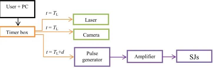
Laser and system synchronization: In our experiments, a unit named Timer box and DynamicStudio v.4.10 software were used. All the control boards of the lasers, cameras, and timers of the input and output signals were placed directly into the main computer. DynamicStudio is a control and processing program for the timer box unit.
In this case, the PIV system was set as a master and the synthetic jet actuators as a slave. The signal generator
received a TTL pulse from the timer box, from the PIV system respectively. This TTL pulse started the modulated sinusoidal signal (prescribed in the pulse generator) which went then via amplifier to the SJs actuators.
The delay inside the electronic synchronization devices does not exceed 3s.
Figure 4 shows the basic principle of synchronization. Recorded phase of the SJs (visible in Fig. 4) can be calculated as
(1)
where n is an integer indicating the number of periods Tmod during the time TL.
Fig. 4. Schematic view of the basic synchronization for PIV measurements.
is a working frequency of a laser ( ), d is a signal delay from the laser pulse (prescribed by the experimenter to shift throughout the SJs (modulated) period).
2.2 Problem parameterization
The primary, continuous axisymmetric jet is characterized by the Reynolds number ! , where "# $ % "#&'() (for simplification calculated as two-dimensional case).
The synthetic jet is defined with the time-mean orifice velocity "*+
, -*./. 0
* , where T is the time period, i.e. T = 1/f and f is the frequency, TE means the extrusion time, u(t) is the periodical axial orifice velocity. The characteristic length scale of SJ is the “stroke length” 1* "*% .
The Reynolds number of the SJ is defined as 2345 "*$67, where h = 1.1 mm and it is the width of the SJ outlet slot.
The strength of the control SJs can be quantified relative to the primary axisymmetric flow in terms of the ratios of velocities cU, flow rates cQ, and momentum cM as 89+
:; <= :
>?+ , 8@ABCA ; :>?+ <=, and 8D E45FG"#H, where ASJ is the cross-section area of the SJ actuator slot (1.1×6.0 mm), n is the number of control SJs (n = 2 in current study), G IJHK is the cross-section area of the main axisymmetric nozzle, ȡ is the working fluid density (air in our case), MSJ is the
time-averaged SJ momentum flux during the extrusion stroke averaged over the entire period. Assuming the “plug flow model”, i.e. the uniform profile of the instantaneous velocity -*LM . -*. and the sinusoidal waveform in time -*. "'()NOP$I., where Umax is the velocity amplitude, the time-averaged SJ momentum flux can be expressed as E45+
FG45, -H./. 0
* . Then the form of cM can be derived as:
8D QH H ABC A < H . (2)
2.2.1 Velocity decomposition
The phase averaging was used for the velocity analysis. The definition of the velocity components in the stream-wise direction is the following:
-. " R "ST. R -U., (3)
where u(t) is the instantaneous velocity, U, UP, and u’ are the time-mean, periodic (coherent), and fluctuation (incoherent, random) components, respectively, and t/T indicates the phase during the cycle.
User + PC
Laser
Timer box Camera
Pulse
generator Amplifier
SJs
t = TLt = TL
A principle of the conditional sampling was used for the velocity decomposition of the PIV data, i.e. sampling has to always occur at the same phase in a process. The sampling starts with the beginning of the period given by a pulse signal from the PIV system (Timer box). In accordance with the pulse signal, the synchronization is performed. The image pairs were acquired at ten equally spaced intervals throughout the actuation cycle, Tmod respectively.
3
Results and discussion
3.1 Unforced flow
The primary flow from the axisymmetric nozzle without SJs control was set at Re = 1600; the time-mean velocity through the nozzle cross-section is calculated as approx. UN = 2.46 m/s.
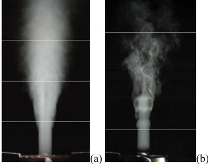
Fig. 5 shows the fog visualization of the unforced jet.
(a) (b)
Fig. 5. Fog visualization of the unforced jet, (a) averaged, (b) instantaneous (pictures taken by Z. Trávníek).
For the PIV experiments, the delay time between two laser pulses was 400 µs. Decreasing of the primary flow time-mean velocity stream-vise is visible in Fig. 6(a). Exponent n = -1.08 confirms the continual (steady) jet; see e.g. Schlichting and Gersten [18]. Fig. 6(b) shows the velocity profiles of the primary flow in distance x/D = 1, 2, 5, 7, and 10. As is visible, in the distance nearest to the orifice, the profile has a character of a “top hat profile”. Axial velocity decreasing and mixing of the air from the outer part of a stream with the ambient air start in distance x/D = (3-7). Fully developed flow starts from the distance approx. x/D> 7 and velocity profiles have similar shape.
3.2 Synthetic jets development
The primary flow was controlled with two SJ actuators worked in the bifurcated mode (Fig. 3(b)). The supply signal of these actuators from the signal generator was set with following parameters: carrier sinusoidal signal with
frequency of f = 850 Hz, modulation frequency fmod = 21.25 Hz, number of waves N = 6, voltage peak-to-peak of the supplying signal, which was leaving the amplifier, was set as 9.60 V. Fig. 7 represents the SJs driving signal modulation. The position of t/Tmod (in range from 0 to 0.9) is also marked there.
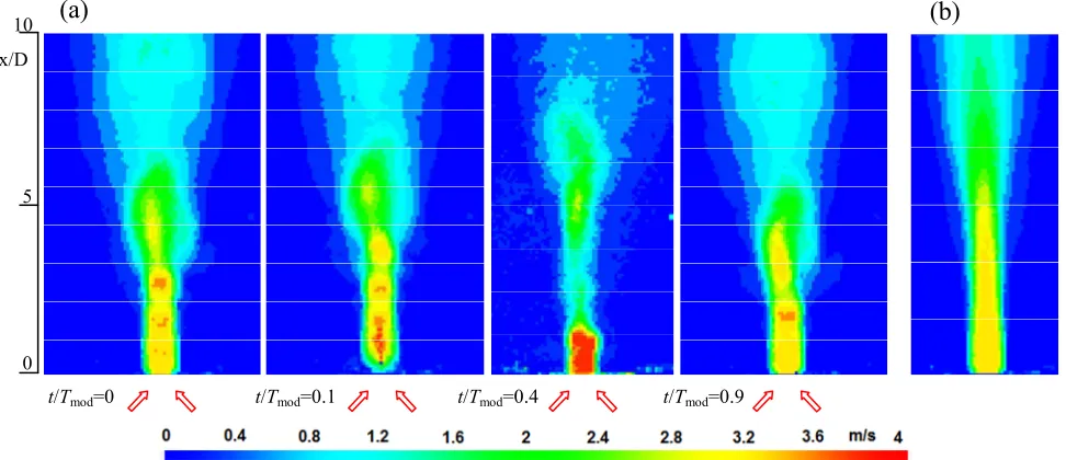
In case of working SJs, the delay time between two pulses was set as 70 µs. The SJs without the primary flow in t/Tmod = 0, 0.1, 0.4, and 0.9 is shown in the form of phase-averaged velocity magnitude contours in discrete drawing style in Fig. 8 and in the form of phase-averaged velocity magnitude profiles in Fig. 9.
(a)
(b)
Fig. 6. (a) Dependence of the primary flow time-mean velocity on the distance from the orifice (logarithmic scale), (b) velocity profiles, Re = 1600.
Fig. 7. Modulated driving signal for SJs.
t/T
mod0 0. 1 0.2 0.3 0.4 0.5 0.6 0.7 0.8 0.9
Fig. 8 shows the bending of the jet in range of 13-18 degrees. In t/Tmod = (0 and 0.1), this bending is caused because the images were taken at the instant of extrusion from the right SJ actuator and suction to the left one. In the interval V % (visible in Fig. 7) each SJ actuator works as with non-modulated sine wave supply. In V % , the time of extrusion as W $ can be supposed. Outside the interval V % , the behavior the SJ actuators moving membranes is different from typical operation of actuator membranes, described e.g. in [19]. The movement of the membrane is stopped here and there is no suction to the orifice. Vortex rings formed at the lip of the orifice during the actuation cycle are moving in x direction without the interaction with suction into the orifice. This vortex movement, looks like a phase of extrusion, takes in interval t/Tmod = (0.3 – 0.9).
On these figures is also visible the maximum extrusion – vortex velocity in t/Tmod = 0.4. Suction can be considered in t/Tmod = 0.1.
Fig. 10 shows the SJ phase averaged velocity magnitude profiles at t/Tmod = 0.1 and 0.4 at different distances from the orifice. As the distance from the orifice increased, the velocity decreased and velocity profiles widened. The bending of SJs is demonstrated with profile’s peak shift to the negative values of r/D.
3.3 Axisymmetric jet under bifurcated mode excitation
Fig. 11 – 14 show the results of the experiments of the primary flow control with activated SJs worked in the
bifurcated mode. These experiments were set at the same conditions as the both previous cases: Re of the primary flow was set as 1600, and SJs were fed with the sinusoidal modulated signal described in the previously text.
Fig. 11 demonstrates the development of controlled axisymmetric jet during the SJs actuation period in form of velocity magnitude. The vortex rings causes in the primary flow the effect called “vena contra”. The action of vortex ring leads to the local narrowing of the primary flow and increasing of the velocity inside the ring. Compared with the unforced jet, the velocity inside the ring increased by approx. 20% (in case of t/Tmod = 0.4). In comparison with [11], where the SJs actuation caused periodic zig-zag vectoring of the primary jet towards left and right direction, in our case due to the actuation frequency and its modulation no or only small bifurcation is manifested. The change of the jet shape and formation and development the vortexes are visible.
Fig. 12 shows phase-averaged velocity magnitude profiles during the actuation cycle in different distances from the orifice. The same width of the profiles is visible in distance x/D = 1. The significant jet narrowing occurs in distance x/D = (2.5-6) for t/Tmod = 0.4.
Phase averaged velocity magnitude profiles in t/Tmod= 0.1 and 0.4 at different distances from the orifice are shown in Fig. 13. The profile in the distance x/D = 5 is slightly shifted to the left because of the vortex which leans the jet to the negative values of r/D.
Fig. 8. SJs without the primary flow: phase-averaged velocity magnitude, PIV experiments, discrete drawing style. 0
5 10 x/D
t/Tmod = 0 t/Tmod = 0.1 t/Tmod= 0.4 t/Tmod = 0.9 18°
14°
(a)
(b)
Fig. 9. SJs without the primary flow: phase-averaged velocity magnitude profiles during the actuation cycle, (a) x/D = 1, (b) x/D = 5.
(a)
(b)
Fig. 10. SJs without the primary flow: phase-averaged velocity magnitude profiles at the instant of (a) maximum suction velocity (t/Tmod =0.1) and (b) maximum extrusion velocity (t/Tmod = 0.4).
Fig. 11. (a) SJs with the primary flow: phase-averaged velocity magnitude, (b) unforced primary axisymmetric flow. PIV experiments, discrete drawing style.
(a)
(b)
0 5 10 x/D
(a)
(b)
Fig. 12. SJs with the primary flow: phase-averaged velocity magnitude profiles during the actuation cycle, (a) x/D = 1, (b) x/D = 5.
(a) (b)
Fig. 13. SJs with the primary flow: phase-averaged velocity magnitude profiles at the instant of (a) maximum suction velocity (t/Tmod=0.1) and (b) maximum extrusion velocity (t/Tmod = 0.4).
(a) (b)
Fig. 14. SJs with the primary flow: (a) dependence of the phase-averaged velocity magnitude at different instances in the period and the time-mean velocity on the distance from the nozzle orifice, (b) dependence of the time-mean velocity on the distance from the nozzle orifice on a logarithmic scale.
Fig. 14(a) demonstrates the dependence of the phase-averaged velocity UP in a different instant of the period and the time-mean velocity U on the distance from the nozzle orifice (the time-mean velocity of the controlled flow was calculated by averaging of all phases during the SJs actuation period Tmod). There was a visible decrease in velocity as the distance increased along x direction. At a distance of x/D = 8, the flow oscillation practically disappeared except t/Tmod = 0.4 (maximum extrusion),
character to the continual fluid jet. This is caused with part of the period outside interval V % , where the new vortex rings are not generated.
4 Conclusions
A round air jet was controlled using two synthetic jets set in the bifurcated mode and located on the circumference of the nozzle exit. The setup was taken from authors of work [11]. The control synthetic jets, the primary axisymmetric jet, and the complex case of the primary jet under the bifurcated mode were studied experimentally by means of PIV method. During the experiments the primary flow was set at Re = 1600, and the synthetic jets actuators were driven with modulated sinusoidal signal. During the experiments it was necessary to synchronize PIV system with SJs actuators.
For the primary flow without affection of SJs, the results correspond with the literature. The affection of SJs enhances the fluid mixing and increases the fluid velocity in the vortex rings, especially at the instant of extrusion. Further downstream the velocity decreases.
Acknowledgements
We gratefully acknowledge the support of the Grant Agency of the Czech Republic (Project No. 16-16596S).
References
[1] M. Gad-El-Hak, Flow control, Cambridge University Press, New Yourk, 2000.
[2] D.A. Tamburello, M. Amitay, Three-dimensional interactions of a freejet with a perpendicular synthetic jet, Journal of Turbulence, Vol. 8, No. 38, 2007.
[3] D.A. Tamburello, M. Amitay, Interaction of a free jet with a perpendicular control jet, Journal of Turbulence, Vol. 8, No. 21, pp. 1-27, 2007.
[4] E.L. Houghton, P.W. Carpenter, Aerodynamics for engineering students, Butterworth-Heinemann, Great Britain, 2006.
[5] M. Ciuryla et al., Flight control using synthetic jet on a Cessna 182 model, Journal of Aircraft, Vol. 44, pp. 642-653, 2007.
[6] A. Nishizava et al.: Toward smart control of separation around a wing – Active separation control system part 2. Proc. 5th Symp. Smart Control of Turbulence, Tokyo, pp. 7-14, 2004. [7] R. Mittal, P. Rampunggoon, On the virtual
aeroshaping effect of synthetic jets. Phys. Of Fluids, Vol. 14, pp. 1533-1536, 2002.
[8] Renault Altica: 44MPG Diesel Concept with Active Airflow Management.
http://www.greencarcongress.com/2006/02/renault_ altica_html.
[9] H. Park et al, Experimental study on synthetic jet array for aerodynamic drag reduction of a simplified
car, Journal of Mechanical Science and Technology, Vol. 27, pp. 3721-3731, 2013.
[10] M. Amitay et al., Separation control in duct flows, Journal of Aircraft, Vol. 39, pp. 616-620, 2002. [11] Z. Trávníek et al., Axisymmetric impinging jet
excited by a synthetic jet system, International Journal of Heat and Mass Transfer, Vol. 55, 2012, pp. 1279-1290.
[12] Z. Trávníek, P.Danová, J. Kordík, T. Vít, M. Pavelka, Heat and mass transfer caused by a laminar channel flow equipped with a synthetic jet array, Transaction of the ASME, Vol. 2, 2010
[13] P. Danová, Z. Trávníek, T. Vít, Experimental investigation of a synthetic jet array in a laminar channel flow, EPJ Web of Conferences, Vol. 45, Article Number: 01002, 2013.
[14] Z. Trávníek, P.Danová, J.H. Lam, V. Timchenko, J. Reizes, Numerical and experimental studies of a channel flow with multiple circular synthetic jets, EPJ Web of Conferences, Vol. 25, Article Number: 01094, 2012.
[15] V. Dvoák, P. Danová, P. Švarc, Experimental investigation into flow in an ejector with four synthetic jets, EPJ Web of Conferences, Vol. 25, Article Number: 02003, 2012.
[16] V. Dvoák, P. Novotný, P. Danová, D. Jašíková, PIV and CTA measurement of constant area mixing in subsonic air ejector, EPJ Web of Conferences, Vol. 45, Article Number: 01003, 2013.
[17] B.L. Smith, A. Glezer, The formation and evolution of synthetic jets, Phys. Fluids, Vol. 10, pp. 2281-2297, 1998.
[18] H. Schlichting, K. Gersten, Boundary-Layer Theory, Springer-Verlag, Berlin, 2000.
[19] T. Vít, P. Danová, Z. Trávníek, Syntetizovaný proud (Synthetic jet), MM PrĤmyslové spectrum, Vol. 3, pp. 104-106, 2007 (in Czech).