585-313-107 108647397 January 2000 Issue 3
Intuity™ CONVERSANT
®
System
Version 7.0
Copyright and Legal Notices
Copyright Copyright © 2000 by Lucent Technologies. All rights reserved.
Printed in the USA.
This material is protected by the copyright laws of the United States and other countries. It may not be reproduced, distributed, or altered in any fashion by any entity (either internal or external to Lucent Technologies), except in accordance with applicable agreements, contracts or licensing, without the express written consent of the Business Communications Systems (BCS) Global Learning Solutions (GLS) organization and the business management owner of the material.
Copyright and Legal Notices
• CLEO Communications — Trademarks: LINKix.
• Hayes Microcomputer Products, Inc. — Trademarks: Hayes, Smartmodem.
• Intel Corporation — Registered trademarks: Pentium.
• Interface Systems, Inc. — Trademarks: CLEO.
• International Business Machines Corporation — Registered trademarks: IBM, VTAM.
• Lucent Technologies — Registered trademarks: 5ESS, AUDIX,
CONVERSANT, DEFINITY, Voice Power. Trademarks: FlexWord, Intuity, Lucent.
• Microsoft Corporation — Registered trademarks: Excel, Internet Explorer, Microsoft, MS, MS-DOS, Windows, Windows NT.
• Minnesota Mining and Manufacturing — Trademarks: 3M.
• Netscape Communications — Trademarks: Netscape Navigator.
• Novell, Inc. — Registered trademarks: Novell.
Copyright and Legal Notices
• Santa Cruz Operation, Inc. — Registered trademarks: UnixWare.
• UNIX System Laboratories, Inc. — Registered trademarks: UNIX.
• Veritas Software Corporation — Trademarks: VERITAS.
• Xerox Corporation — Trademarks: Ethernet.
Limited Warranty Lucent Technologies provides a limited warranty on this product. Refer to the “Limited Use Software License Agreement” card provided with your package. Lucent Technologies has determined that use of this electronic data delivery system cannot cause harm to an end user's computing system and will not assume any responsibility for problems that may arise with a user's computer system while accessing the data in these document.
Every effort has been made to make sure that this document is complete and accurate at the time of release, but information is subject to change.
United States FCC Compliance Information
Copyright and Legal Notices
interference, in which case the user will be required to correct the interference at his own expense.
Canadian Department of Communications (DOC) Interference Information
This digital apparatus does not exceed the Class A limits for radio noise emissions set out in the radio interference regulations of the Canadian Department of Communications.
Le Présent Appareil Nomérique n’émet pas de bruits radioélectriques dépassant les limites applicables aux appareils numériques de la class A préscrites dans le reglement sur le brouillage radioélectrique édicté par le ministére des Communications du Canada.
European Union Declaration of Conformity
Lucent Technologies Business Communications Systems declares that the Intuity™ CONVERSANT® System equipment specified in this document conforms to the referenced European Union (EU) Directives and Harmonized Standards listed below: EMC Directive 89/336/EEC Low-Voltage Directive 73/23/EEC. The “CE” mark affixed to the equipment means that it conforms to the above directives.
Telecom New Zealand Ltd Warning Notices
Copyright and Legal Notices
make or model, nor does it imply that any product is compatible with all of Telecom’s network services.
IMPORTANT NOTICE: Under power failure conditions, this device may not operate. Please ensure that a separate telephone, not dependent on local power, is available for emergency use.
AUTOMATIC RE-ATTEMPTS TO THE SAME NUMBER: Some parameters required for compliance with Telecom’s Telepermit requirements are dependent on the equipment (PC) associated with this device. The associated equipment shall be set to operate within the following limits for compliance with Telecom specifications:
• There shall be no more than 10 call attempts to the same number within any 30 minute period for any single manual call initiation, and,
Copyright and Legal Notices
USER INSTRUCTIONS (AUTOMATIC CALL SETUP): This equipment shall not be set up to make automatic calls to the Telecom "111" emergency service.
CALL ANSWERING (AUTOMATIC ANSWERING EQUIPMENT): Some parameters required for compliance with Telecom’s Telepermit requirements are dependent on the equipment (PC) associated with this device. In order to operate within the limits for compliance with Telecom specifications, the associated equipment shall be set to ensure that calls are answered between 3 and 30 seconds of receipt of ringing.
Toll Fraud Toll fraud is the unauthorized use of your telecommunications system by an unauthorized party, for example, persons other than your company’s employees, agents, subcontractors, or persons working on your company’s behalf. Note that there may be a risk of toll fraud associated with your telecommunications system and, if toll fraud occurs, it can result in substantial additional charges for your telecommunications services.
Your Responsibility for Your System’s Security
Copyright and Legal Notices
prevent unauthorized use of common-carrier telecommunication services or facilities accessed through or connected to it. Lucent Technologies will not be responsible for any charges that result from such unauthorized use.
Lucent Technologies Fraud Intervention and Corporate Security
If you suspect that you are being victimized by toll fraud and you need technical support or assistance, call the Lucent Technologies National Customer Care Center Toll Fraud Intervention Hotline at 1 800 643-2353. Aside from whether immediate support is required, all toll fraud incidents involving Lucent products or services should be reported to Lucent Corporate Security at 1 800 821-8235. In addition to recording the incident, Lucent Corporate Security is available for consultation on security issues,
Copyright and Legal Notices
Documentation Ordering Information
To order a document, contact the Lucent Technologies Publications Center and specify the 9-digit document number, the issue number, and the issue date.
Write, Call, or Fax
Lucent Technologies Publications Center 2855 N. Franklin Road
Indianapolis, IN 46219
Voice 1 800 457-1235 International Voice 317 322-6791 FAX 1 800 457-1764 International FAX 317 322-6699
World Wide Web
Use a web browser to reach one of the following sites. Click Documents and follow the instructions at the site.
• Organizations within Lucent Technologies http://www.cic.lucent.com
Copyright and Legal Notices
Standing Orders
Contents
Copyright and Legal Notices
ii
Copyright. . . .ii
Acknowledgment . . . .ii
Trademarks . . . .ii
Limited Warranty . . . iv
United States FCC Compliance Information . . . iv
Canadian Department of Communications (DOC) Interference Information . . v
European Union Declaration of Conformity . . . v
Telecom New Zealand Ltd Warning Notices . . . v
Toll Fraud. . . .vii
Documentation Ordering Information . . . ix
About This Book
xxv
Overview . . . xxvIntended Audience . . . xxvi
How to Use This Book . . . xxvi
How This Book Is Organized. . . xxvi
Contents
Keyboard and Telephone Keypad Representations . . . xxxiii
Cross References and Hypertext . . . xxxiv
Screen Displays . . . xxxiv
Other Typography . . . xxxv
Safety and Security Alert Labels. . . xxxvi
Getting Help . . . xxxvii
Technical Assistance. . . . xxxviii
Web Site . . . .xxxviii
Contact Numbers . . . .xxxviii
Related Resources. . . xxxix
Training . . . xxxix Documentation . . . xl
Using the CD-ROM Documentation . . . . xlii
Contents
Contact Us Directly . . . xlvi
1 Getting Inside the Computer
1
Overview . . . 1
Protecting Against Damage from Electrostatic Discharge . . . 2
Removing Power from the MAP/5P . . . 7
Removing the Dress Cover . . . 9
Replacing the Dress Cover . . . . 11
Restoring Power to the MAP/5P . . . . 11
2 Installing or Replacing Circuit Cards
12
Overview . . . . 12General Procedures . . . . 13
Removing a Circuit Card . . . 13
Removing the Intuity CONVERSANT System from Service . . . 14
Accessing the Circuit Card . . . 14
Extracting the Circuit Card . . . 14
Installing a Circuit Card . . . 16
Inserting the Circuit Card . . . 16
Reassembling the MAP/5P . . . 18
Restoring the Intuity CONVERSANT System to Service . . . 18
Contents
Installing the Asynchronous SuperSerial Card Driver . . . 21
PCI Ethernet LAN Circuit Cards . . . 25
SMC8432 Circuit Card . . . 25
SMC9332 Circuit Card . . . 27
Installing a PCI LAN Circuit Card . . . 28
Replacing a PCI LAN Circuit Card. . . 37
FIFO/SIB Synchronous Host Circuit Card . . . 38
Jumper Settings . . . 40
Switch Settings . . . 41
Remote Maintenance Circuit Card. . . 43
Types of Remote Maintenance Circuit Cards . . . 45
Setting the Resource Options . . . 48
Inserting the Remote Maintenance Circuit Card . . . 48
Installing the Remote Maintenance Circuit Card Software Package . . . 51
SCSI Controller Circuit Card . . . 53
Tip/Ring Circuit Cards . . . 59
AYC10 Tip/Ring Circuit Card. . . 59
AYC30 Tip/Ring Circuit Card. . . 61
Installing the Tip/Ring Circuit Card Driver . . . 63
Contents
Identifying a Failed Hard Disk Drive . . . . 82
Contents of the Hard Disk Drives in a Two-Drive System . . . 82
Identifying a Hard Disk Drive 0 Failure in a Nonmirrored or Single-Disk System. . . 84
Identifying a Hard Disk Drive 1 Failure in a Nonmirrored System . . . 85
Identifying a Hard Disk Drive Failure in a Mirrored System . . . 85
Recovering from a Hard Disk Drive 0 Failure . . . . 86
Recovering from a Hard Disk Drive 0 Failure (Nonmirrored or Single-Disk System) . . . 86
Recovering from a Hard Disk Drive 0 Failure (Mirrored System). . . 87
Recovering from a Hard Disk Drive 1 Failure . . . . 93
Recovering from a Hard Disk Drive 1 Failure (Nonmirrored System) . . . 94
Recovering from a Hard Disk Drive 1 Failure (Mirrored System). . . 96
Replacing a Hard Disk Drive . . . 100
Replacing Hard Disk Drive 0 . . . 102
Hard Disk Drive 0 Removal . . . 102
Hard Disk Drive 0 Installation . . . 104
Replacing Hard Disk Drive 1 . . . 106
Hard Disk Drive 1 Removal . . . 106
Hard Disk Drive 1 Installation . . . 109
Adding a Hard Disk Drive . . . 113
Adding a Hard Disk Drive to a System for Mirroring . . . 113
Contents
Cleaning a Hard Disk Drive . . . 124
Using the fdisk Command . . . 124
Low-Level Formatting the Hard Disk Drive . . . 127
Low-Level Formatting with a P5 200 MHz CPU Circuit Card . . . 127
Mirroring . . . 129
Establishing Mirroring . . . 129
Removing Mirroring . . . 134
Disk Reuse. . . 135
Reusing for Mirroring . . . 135
Reusing for Speech . . . 135
4 Replacing Other Components
137
Overview . . . 137Replacing the Cartridge Tape Drive . . . 138
Removing a Cartridge Tape Drive . . . 141
Removing the Intuity CONVERSANT System from Service . . . 141
Accessing the Cartridge Tape Drive . . . 141
Contents
Replacing a CMOS Battery . . . 145
Removing a CMOS Battery . . . 147
Accessing the CMOS Battery . . . 147
Extracting the CMOS Battery . . . 147
Installing a CMOS Battery . . . 147
Inserting the CMOS Battery . . . 148
Verifying the CMOS Settings. . . 148
Replacing the Diskette Drive . . . 148
Removing the Diskette Drive . . . 149
Accessing the Diskette Drive . . . 149
Extracting the Diskette Drive . . . 149
Installing the Diskette Drive . . . 152
Inserting the Diskette Drive . . . 152
Replacing Fans . . . 154
Replacing the Circuit Card Cage Fan . . . 155
Removing a Circuit Card Cage Fan . . . 155
Installing a Circuit Card Cage Fan . . . 156
Replacing a CPU Fan . . . 158
Removing a CPU Fan . . . 158
Installing a CPU Fan . . . 159
Replacing Memory Modules . . . 160
Removing SIMMs . . . 161
Contents
Extracting the SIMMs . . . 163
Installing SIMMs . . . 165
Inserting the SIMMs . . . 165
Reassembling the MAP/5P . . . 166
Replacing the Motherboard . . . 166
Removing the Motherboard . . . 166
Accessing the Motherboard . . . 167
Extracting the Motherboard. . . 169
Installing the Motherboard . . . 170
Verifying the Resource Options. . . 170
Inserting the Motherboard. . . 173
Reassembling the MAP/5P . . . 175
Restoring the Intuity CONVERSANT System to Service . . . 176
Replacing the Power Supply . . . 182
Removing the Power Supply . . . 184
Accessing the Power Supply. . . 184
Extracting the Power Supply . . . 184
Installing the Power Supply . . . 188
Contents
Inserting the Riser Card . . . 193
Reassembling the MAP/5P . . . 193
Restoring the Intuity CONVERSANT System to Service . . . 194
Replacing a Terminator SIP . . . 194
5 Installing Base System Software
197
Overview . . . 197Installing Base System Software. . . 198
Beginning the UnixWare Installation . . . 198
Setting Up the UnixWare Environment . . . 202
Initializing the Hard Disk Drives . . . 209
Transferring the UnixWare Files. . . 221
Installing the Application Server . . . 223
Activating the Volume Manager . . . 225
Installing the LAN Card Driver Package . . . 226
Setting up the Monitor . . . 226
Initializing the Mouse. . . 231
Testing the Mouse . . . 235
6 Installing the Intuity CONVERSANT System Software
236
Overview . . . 236Contents
7 Installing the Optional Feature System Software
250
Overview . . . 250
Installing Software Packages Using the Unix Management Screens . . . 251
Installing the Hardware Resource Allocator Package . . . 253
Installing the Asynchronous Host Toolkit. . . 256
Installing the ASYNC_TEST Transaction Script Builder Backup . . . 259
Installing the ASYNC_TEST Speech Script Builder Backup . . . 261
Installing the Analog Switch Interface Package . . . 263
Installing the Backup/Restore Utility . . . 265
Installing the Call Bridge Application Package . . . 267
Installing the Data Collection Toolkit . . . 269
Installing the Enhanced Basic Speech Package . . . 272
Installing the Feature Test Script Package . . . 274
Installing the LAN Adapter Setup Program . . . 279
Installing the Form Filler Application . . . 281
Contents
Installing the cleo_HTE Package . . . 305
Completing the Installation . . . 307
Installing the Host Packages . . . 308
Installing the Synchronous Host Interface Package . . . 308
Installing the 3270 Enhanced File Transfer Package . . . 311
Installing the NetView Alarm Interface Package . . . 313
Installing the ORACLE Development Packages . . . 315
Package List . . . 315
Installation Requirements . . . 316
Procedures . . . 316
Increasing ORACLE File System . . . 316
Creating a Temporary File System . . . 317
Installing the Intuity ORACLE 7 Pro*C Package . . . 317
Installing the Intuity ORACLE Developer 2000 Toolkit . . . 319
Post Installation Setup . . . 326
Installing the Intuity ORACLE 7 Patch 19 . . . 327
Completing Installation . . . 328
Installing the ORACLE SQL*Net TCP/IP Package. . . 329
Installing the Script Builder Package. . . 331
Installing the Script Builder FAX Actions Package . . . 334
Installing the Unix Management Screens Package . . . 342
Contents
Using the Command Line . . . 346 Using the Intuity CONVERSANT Screens. . . 348
Appendix A: System Configuration
351
Overview . . . 351 System Configuration . . . 352
Memory . . . 352 Component Assignments. . . 354 Circuit Cards . . . 354 Operating Hardware . . . 356
Hardware Resource Allocator Operation . . . 359
Contents
Appendix B: Component Ordering Numbers
383
Overview . . . 383 Component Ordering Numbers . . . 384
Appendix C: How to Build a System Using This Book
388
Overview . . . 388 Checklist for Building a System . . . 389
Appendix D: Disaster Recovery Checklists
391
Overview . . . 391 Disaster Recovery Checklists . . . 392
Checklist for Software Reloading on a Nonmirrored Intuity
CONVERSANTSystem with Existing Hard Disk Drives . . . 392 Checklist for a Intuity CONVERSANT System with
All New Hard Disk Drives . . . 393 Checklist for a Nonmirrored Intuity CONVERSANT System with a
New Hard Disk Drive 0 and an Existing Hard Disk Drive 1 . . . 395 Checklist for a Nonmirrored Intuity CONVERSANT System with an
Existing Hard Disk Drive 0 and a New Hard Disk Drive 1 . . . 396 Checklist for a Mirrored Intuity CONVERSANT System with a
New Hard Disk Drive 0 and an Existing Hard Disk Drive 1 . . . 398 Checklist for a Mirrored Intuity CONVERSANT System with an
Contents
Appendix E: MAP/5P Platform Alarms
402
Overview . . . 402 Platform Alarms . . . 403
Glossary
407
About This Book
Overview
This book contains information for troubleshooting and diagnosing problems associated with the Intuity CONVERSANT MAP/5P and hardware. It also includes component replacement procedures as well as installation procedures for base system software, Intuity CONVERSANT system software, and optional feature software. Appendices contain a system configuration description, a list of component ordering numbers, a checklist for building a system, and checklists for disaster recovery.
Note: To repair or alter the configuration of your system, you must have
About This Book Intended Audience
Intended Audience
This book is intended primarily for the on-site service technician and system administrators. Secondary audiences include the following:
• Field support — Technical Service Organization (TSO)
• Lucent Technologies Helpline personnel
We assume that the primary users of this book have completed the MAP/5P hardware installation training course (see Training on page xxxix).
How to Use This Book
This book is designed to help you maintain your Intuity CONVERSANT system. It should be used as a quick-reference to obtain specific information you may need on a particular topic.
How This Book Is
About This Book How to Use This Book
• Chapter 3, Replacing a Hard Disk Drive — contains procedures to identify and recover from hard disk drive failures, to add a hard disk drive, to establish disk mirroring, and to clean a hard disk drive.
• Chapter 4, Replacing Other Components — contains procedures to replace the MAP/5P internal components and information on the correct configuration and settings for individual components.
• Chapter 5, Installing Base System Software — contains the installation procedures necessary to reload the UnixWare operating system software.
• Chapter 6, Installing the Intuity CONVERSANT System Software — contains procedures to install the Intuity CONVERSANT system software.
• Chapter 7, Installing the Optional Feature System Software — contains procedures to install all the software that was not included on the application software cartridge tape.
• Appendix A, System Configuration — describes the configuration of components in the MAP/5P and the operation of the Hardware Resource Allocator.
• Appendix B, Component Ordering Numbers — lists the ordering numbers for replacement components used in the MAP/5P.
About This Book Conventions Used in This Book
• Appendix D, Disaster Recovery Checklists — provides a general task checklist for disaster recovery with references to required procedures.
• Appendix E, MAP/5P Platform Alarms — describes the platform alarms (not generated by the Intuity CONVERSANT system and not documented in the Intuity CONVERSANT alarm logs).
• Glossary — Defines the terms, abbreviations, and acronyms used in system documentation.
• Index — Alphabetically lists the principal subjects covered in the book.
Conventions Used in This Book
Understanding the typographical and other conventions used in this book is necessary to interpret the information.
Terminology • The word “type” means to press the key or sequence of keys specified. For example, an instruction to type the letter “y” is shown as
About This Book Conventions Used in This Book
• The word “select” means to move the cursor to the desired item and then press E NT E R. For example, an instruction to move the cursor to the start test option on the Network Loop-Around Test screen and then press
E N T E R is shown as Select Start Test.
• The system display menus, screens, and windows. Menus allow you to select options or to choose to view another menu, screen, or window (Figure 1 on page xxx). Screens and windows both show and request system information (Figure 2 on page xxx through Figure 5 on page xxxiii).
Note: Screens shown in this book are examples only. The screens you
About This Book Conventions Used in This Book
Figure 1. Example of an Intuity CONVERSANT Menu
About This Book Conventions Used in This Book
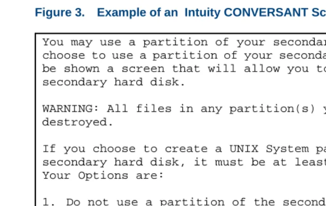
Figure 3. Example of an Intuity CONVERSANT Screen Requesting Information
You may use a partition of your secondary hard disk. If you choose to use a partition of your secondary hard disk you will be shown a screen that will allow you to partition your secondary hard disk.
WARNING: All files in any partition(s) you delete will be destroyed.
If you choose to create a UNIX System partition on your secondary hard disk, it must be at least 40 MBs.
Your Options are:
1. Do not use a partition of the secondary hard disk for the UNIX System.
2. Use a partition of the secondary hard disk for the UNIX System.
About This Book Conventions Used in This Book
Figure 4. Example of an Intuity CONVERSANT Screen Showing Information
In order to install UnixWare, you must reserve a partition (a portion of your hard disk’s space) on your primary hard disk for the UNIX System. After you press ‘ENTER’ you will be shown a screen that will allow you to create new partitions, delete existing partitions or change the active partition of your primary hard disk (the partition that your computer will boot from).
WARNING: All files in any partition(s) you delete will be destroyed. If you wish to attempt to preserve any files from an existing UNIX System, do not delete its partition(s).
About This Book Conventions Used in This Book
Figure 5. Example of an CONVERSANT Window Showing Information
Keyboard and Telephone Keypad Representations
• Keys that you press on your terminal or PC are represented as small capitalized B OL D text. For example, an instruction to press the enter key is shown as
Press E N T E R.
• Two or three keys that you press at the same time on your terminal or PC (that is, you hold down the first key while pressing the second and/or third key) are represented as small capitalized B OL D text. For example, an instruction to press and hold the Alt key while typing the letter “d” is shown as
About This Book Conventions Used in This Book
• Function keys on your terminal, PC, or system screens, also known as soft keys, are represented as small capitalized B O L D text followed by the function or value of that key enclosed in parentheses. For example, an instruction to press function key 3 is shown as
Press F 3 (Choices).
• Keys that you press on your telephone keypad appear in small capitalized
B O L D text. For example, an instruction to press the first key on your telephone keypad is shown as
Press 1 to record a message.
Cross References
and Hypertext Blue underlined type indicates a cross reference or hypertext link that takes you to another location in the document when you click on it with your mouse.
Screen Displays • Values, system messages, field names, prompts that appear on the screen, and simulated screen displays appear in typewriter-style constant width type, as shown in the following examples: Enter the number of ports to be dedicated to outbound traffic in the
About This Book Conventions Used in This Book
• The sequence of menu options that you must select to display a specific screen or submenu is shown as follows:
Start at the Voice System Administration menu and select:
In this example, you would access the Voice System Administration menu and select the Reports menu. From the Reports menu, you would then select the Message Log Report option.
Other Typography • Commands and text you type in or enter appear in bold type, as in the following examples:
Enter change-switch-time-zone at the Enter command: prompt. Type high or low in the Speed: field.
About This Book Safety and Security Alert Labels
• Command variables are shown in bold italic type when they are part of what you must type in, and in blue italic type when they are referred to, for example:
Enter ch ma machine_name, where machine_name is the name of the call delivery machine you just created.
• Command options are shown inside square brackets, for example: Enter connect switchname [-d] [-b | -w]
Safety and Security Alert Labels
This book uses the following symbols to call your attention to potential problems that could cause personal injury, damage to equipment, loss of data, service interruptions, or breaches of toll fraud security:
!
CAUTION:
About This Book Getting Help
!
DANGER:
Indicates the presence of a hazard that if not avoided will cause death or severe personal injury.
!
SECURITY ALERT:
Indicates the presence of a toll fraud security hazard. Toll fraud is the unauthorized use of a telecommunications system by an unauthorized party.
Getting Help
The Intuity CONVERSANT system provides online help to assist you during installation, administration, and application development tasks.
To use the online help:
• Press F 1 (Help) when you are in a menu or window.
The first time you press F 1, the system displays information about the currently active window or menu.
~ When you are in a window, the help explains the purpose of the window and describes its fields.
About This Book Technical Assistance
If you press F 1 again, the system displays a General Help screen that explains how to use the online help.
• Press F 2 (Choices) when you are in a field.
The system displays valid field choices either in a pop-up window or on the status line directly above the function keys.
• Press F 6 (Cancel) to exit the online help.
Technical Assistance
Web Site The following customer support web site contains resources where you can find solutions for technical problems:
http://support.lucent.com
Contact Numbers Technical assistance on the Intuity CONVERSANT product is available through the following telephone contacts:
About This Book Related Resources
• In any other country, call your local distributor or check with your project manager or systems consultant.
Related Resources
Additional documentation and training material is available for you to learn more about the Intuity CONVERSANT product.
Training To obtain training on the Intuity CONVERSANT product, contact the BCS Education and Training Center at one of the following numbers:
• Organizations within Lucent Technologies (904) 636-3261
• Lucent Technologies customers and all others (800) 255-8988 You can also view information on Intuity CONVERSANT training at the Global Learning Solutions (GLS) web site at one of the following web links:
• Organizations within Lucent Technologies http://training.gls.lucent.com
About This Book Related Resources
The courses listed below are recommended. Other courses are available.
• For technicians doing repairs on Intuity CONVERSANT V7.0 systems
~ BTT509H, CONVERSANT Installation and Maintenance Voice Information System
• For technicians and administrators
~ BTC344M, Intuity CONVERSANT V7 Administration Overview (CD-ROM)
• For application developers
~ BTC128H, Introduction to Script Builder
~ BTC166H, Introduction to Voice@Work
~ BTC204H, Intermediate Voice@Work
~ BTC301H, Advanced CONVERSANT Programming
Documentation Appendix A, "Documentation Guide," in Intuity CONVERSANT System
Version 7.0 System Description, 585-313-204, describes in detail all books
About This Book Related Resources
Additional Suggested Documentation
It is suggested that you also obtain and use the following book for information on security and toll fraud issues:
• GBCS Products Security Handbook, 555-025-600
For Troubleshooting Information
Basic troubleshooting information is available in “Troubleshooting” in the
Intuity CONVERSANT System Reference, 585-313-205.
For Diagnostic Information
Instructions for conducting diagnostics are available in “Diagnostics” in the
Intuity CONVERSANT System Reference, 585-313-205.
For Common System Procedures
Instructions for conducting common system procedures are available in “Common System Procedures” in the Intuity CONVERSANT System
Reference, 585-313-205.
For Installation Information
Instructions for installing or reinstalling system elements are available in
Intuity CONVERSANT System Version 7.0 New System Installation,
About This Book Using the CD-ROM Documentation
Obtaining Printed Versions of the Documentation
See Documentation Ordering Information on page ix of Copyright and Legal Notices for information on how to purchase Intuity CONVERSANT
documentation in printed form. You can also print documentation locally from the CD-ROM (see Printing the Documentation on page xliv).
Using the CD-ROM Documentation
Lucent Technologies ships the documentation in electronic form. Using the Adobe Acrobat Reader application, you can read these documents on a Windows PC, on a Sun Solaris workstation, or on an HP-UX workstation. Acrobat Reader displays high-quality, print-like graphics on both UNIX and Windows platforms. It provides scrolling, zoom, and extensive search capabilities, along with online help. A copy of Acrobat Reader is included with the documents.
Note: If viewing documents online, it is recommended that you use a
About This Book Using the CD-ROM Documentation
Adjusting the Window Size
On HP and Sun workstations, you can control the size of the reader window by using the -geometry argument. For example, the command string acroread -geometry 900x900 mainmenu.pdf opens the main menu with a window size of 900 pixels square.
Hiding and Displaying Bookmarks
By default, the document appears with bookmarks displayed on the left side of the screen. The bookmarks serve as a hypertext table of contents for the chapter you are viewing. You can control the appearance of bookmarks by selecting View | Page Only or View | Bookmarks and Page.
Using the Button Bar
The button bar can take you to the book’s Index, table of contents, main menu, and glossary. It also lets you update your documents. Click the corresponding button to jump to the section you want to read.
Using Hypertext
Links Hypertext links appears in blue underlined text. These links are shortcuts to other sections or books.
Navigating with Double Arrow Keys
The double right and double left arrows ( and ) at the top of the Acrobat Reader window are the back and forward functions. The go-back button takes you to the last page you visited prior to the current page. Typically, you use to jump back to the main text from a cross reference or illustration.
About This Book Using the CD-ROM Documentation
Displaying Figures If lines in figures appear broken or absent, increase the magnification. You might also want to print a paper copy of the figure for better resolution.
Printing the
Documentation Note: For information on purchasing printed copies of the documents, see Obtaining Printed Versions of the Documentation on page xlii.
If you would like to read the documentation in paper form rather than on a computer monitor, you can print all or portions of the online screens.
Printing an Entire Document
To print an entire document, do the following:
1 From the documentation main menu screen, select one of the print-optimized documents. Print-print-optimized documents print two-screens to a side, both sides of the sheet on 8.5x11-inch or A4 paper.
2 Select File | Print.
About This Book How To Comment on This Book
Printing Part of a Document
To print a single page or a short section, you can print directly from the online version of the document.
1 Select File | Print.
2 Enter the page range you want to print, or select Current. The document prints, one screen per side, two sides per sheet.
How To Comment on This Book
While we have tried to make this document fit your needs, we are interested in your suggestions for improving it and urge you to send your comments to us.
Comment Form A comment form, available in paper and electronic versions, is available via the documentation CD-ROM. To use the comment form:
1 Select Comments from the Main Menu of the CD-ROM.
2 Follow the instructions provided on the CD-ROM to do one of the following:
About This Book How To Comment on This Book
Contact Us Directly If you prefer not to use the comment form, you can contact us directly at the following address or fax number.
Note: Direct your correspondence to the attention of the Lucent
Technologies Intuity CONVERSANT writing team. Be sure to mention the title of the book on which you are commenting. Lucent Technologies
GLS Information Development Division Room 22-2H15
1
Getting Inside the Computer
Overview
This chapter provides the correct procedures for accessing the internal components of the MAP/5P.
Topics covered include:
• Protecting Against Damage from Electrostatic Discharge on page 2
• Power removal and restoration
~ Removing Power from the MAP/5P on page 7
~ Restoring Power to the MAP/5P on page 11
• Computer chassis access
~ Removing the Dress Cover on page 9
1
Getting Inside the Computer Protecting Against Damage from Electrostatic DischargeProtecting Against Damage from Electrostatic Discharge
!
CAUTION:
Read this section before unpacking the MAP/5P. You must observe proper grounding techniques to prevent the discharge of static electricity from your body into ESD-sensitive components.
Circuit cards and packaging materials that contain ESD-sensitive components are usually marked with a yellow-and-black warning symbol (Figure 6 on page 2).
Figure 6. ESD Warning Symbol
1
Getting Inside the Computer Protecting Against Damage from Electrostatic Discharge!
CAUTION:
Ensure that your palm is not in contact with the non-component side of the board.
To avoid damaging ESD-sensitive components, follow these rules:
• Handle ESD-sensitive circuit cards only after attaching a wrist strap to your bare wrist. Attach the other end of the wrist strap to a ground that terminates at the system ground, such as any unpainted metallic chassis surface.
1
Getting Inside the Computer Protecting Against Damage from Electrostatic Discharge1
Getting Inside the Computer Protecting Against Damage from Electrostatic DischargeFigure 8. How to Hold a Large Circuit Card
• Keep circuit cards away from plastics and other synthetic materials such as polyester clothing.
1
Getting Inside the Computer Protecting Against Damage from Electrostatic Discharge• Hold devices such as a hard disk, floppy drive, or streaming tape in the same manner as a large circuit card. The ESD-sensitive area of these components is located on the bottom surface (Figure 9 on page 6).
Figure 9. ESD-Sensitive Area of an Electronic Component
1
Getting Inside the Computer Removing Power from the MAP/5PRemoving Power from the MAP/5P
The MAP/5P requires a dedicated circuit with a dedicated circuit breaker. The power cord connects to the rear of the MAP/5P at the point labeled AC power inlet receptacle (Figure 10 on page 8).
Before you begin any work in the MAP/5P complete the following procedure to remove power from the MAP/5P:
1 Shut down the INTUITY CONVERSANT system. See “Administer the Voice System,” in “Common System Procedures,” in the Intuity
CONVERSANT System Reference, 585-313-205.
2 Turn off the monitor’s power switch.
The green or amber lamp on the front bottom of the monitor should be off.
3 Turn off the power switch on the front of the MAP/5P.
The green lamp labeled POWER ON on the front of the unit should be off.
4 Unplug the MAP/5P from the power outlet.
5 Remove the MAP/5P power cord from the AC receptacle in the wall.
1
Getting Inside the Computer Removing Power from the MAP/5PFigure 10. Back View of the MAP/5P
1. Power supply fan intake 2. Keyboard connector 3. Mouse connector 4. COM1
5. COM2 6. Parallel port 7. Video connector 8. AC power supply outlet 9. Dress cover lock
1
Getting Inside the Computer Removing the Dress CoverRemoving the Dress Cover
The dress cover provides protection for the internal components of the MAP/5P. You must remove the dress cover to access these components.
WARNING:
!
Shut power off before removing the dress cover. See Removing Power from the MAP/5P on page 7 for the procedure.
To remove the dress cover, do the following:
1 Place the dress cover lock (Figure 10 on page 8) in the open position.
Note: Figure 10 on page 8 shows the dress cover lock in the locked
position.
2 Simultaneously compress the dress cover latches on either side of the MAP/5P (Figure 11 on page 10).
1
Getting Inside the Computer Removing the Dress CoverFigure 11. Removing the Dress Cover
1
Getting Inside the Computer Replacing the Dress CoverReplacing the Dress Cover
To replace the dress cover, do the following:
1 Align the dress cover with the MAP/5P chassis.
2 Slide the dress cover back until it locks into place.
3 Close the dress cover lock on the back of the MAP/5P chassis.
Restoring Power to the MAP/5P
To restore power to the MAP/5P, do the following:
1 Plug the MAP/5P power cord into the designated power outlet.
2 Fasten the power cord to the MAP/5P dress cover lock using a cable tie.
Note: Leave some slack in the power cord between the dress cover lock
and the back of the MAP/5P.
3 Turn on the monitor’s power switch.
The green or amber lamp on the front bottom of the monitor should be lit.
2
Installing or Replacing Circuit
Cards
Overview
This chapter contains information to ensure that Intuity CONVERSANT circuit cards are installed correctly and resource options are set correctly.
Topics covered include:
• Configuring circuit cards in the MAP/5P
• Types of circuit cards
• General steps for circuit card installation
• Specific procedures for installation of standard and optional MAP/5P circuit cards
2
Installing or Replacing Circuit Cards General ProceduresGeneral Procedures
The general procedures include:
• Removing a Circuit Card on page 13
• Installing a Circuit Card on page 16
Removing a Circuit Card
!
CAUTION:
Observe proper electrostatic discharge precautions when you handle computer components. Wear an antistatic wrist strap that touches your bare skin and connect the strap cable to an earth ground. See Protecting Against Damage from Electrostatic Discharge on page 2 in Chapter 1, Getting Inside the Computer .
To remove a circuit card, the following procedures are required:
• Removing the Intuity CONVERSANT System from Service on page 14
• Accessing the Circuit Card on page 14
2
Installing or Replacing Circuit Cards General ProceduresRemoving the Intuity
CONVERSANT System from Service
To remove the Intuity CONVERSANT system from service, do the following:
1 Verify that the replacement equipment is on site and appears to be in usable condition, with no obvious shipping damage.
2 Stop the voice system. See “Administer the Voice System,” in “Common System Procedures,” in the Intuity CONVERSANT System Reference, 585-313-205.
3 Shut down the system. See “Shut Down the System,” in “Common System Procedures,” in the Intuity CONVERSANT System Reference, 585-313-205.
4 Remove the incoming power. See Removing Power from the MAP/5P on page 7 in Chapter 1, Getting Inside the Computer .
Accessing the
Circuit Card To access the circuit card, remove the dress cover. See Removing the Dress Cover on page 9 in Chapter 1, Getting Inside the Computer .
Extracting the Circuit Card
To extract the circuit card, do the following:
2
Installing or Replacing Circuit Cards General Procedures3 If there are cables attached to other circuit cards which would impede the removal of the card, disconnect them and place them to the side.
Note: Pay close attention to the connectivity of each cable.
4 Remove the retaining screw from the circuit card faceplate and save it.
5 Remove the circuit card from the backplane slot by gently pulling on each corner of the card.
Note: Note the slot assignment because you must install the
replacement card in the same backplane slot. See Component Assignments on page 354 in Appendix A, System Configuration, for circuit card slot assignments.
6 Remove the circuit card from the MAP/5P.
!
CAUTION:
Hold the circuit card carefully by the edges and place it on a grounded mat. See Protecting Against Damage from Electrostatic Discharge on page 2 in Chapter 1, Getting Inside the Computer , for detailed electrostatic discharge precautions.
2
Installing or Replacing Circuit Cards General ProceduresInstalling a Circuit Card
!
CAUTION:
Observe proper electrostatic discharge precautions when you handle computer components. Wear an antistatic wrist strap that touches your bare skin and connect the strap cable to an earth ground. See Protecting Against Damage from Electrostatic Discharge on page 2 in Chapter 1, Getting Inside the Computer .
To install a circuit card, the following procedures are required:
• Inserting the Circuit Card on page 16
• Reassembling the MAP/5P on page 18
• Restoring the Intuity CONVERSANT System to Service on page 18
Note: If you are adding an additional circuit card to the Intuity
2
Installing or Replacing Circuit Cards General ProceduresNote: Keep the package and all ESD-protective wrapping. You must
re-use the material in which the replacement circuit card was packaged to meet the manufacturer’s warranty.
2 Verify the circuit card switch and jumper settings. Ensure address switches and jumpers are set to match the old card.
Note: See the specific instructions listed later in this chapter for each
type of circuit card you are installing then continue with step 3.
3 If the circuit card is the last circuit card connected to either end of the TDM bus, you must ensure that the TDM bus terminator single in-line packages (SIPs) are in place on the circuit card. See Replacing a Terminator SIP on page 194 in Chapter 4, Replacing Other Components .
If the circuit card is not the last circuit card on the bus, you must remove the SIPs.
Note: “Last circuit card connected” means that there are no other cards
between the circuit card and the end of the bus. There may, however, be empty connectors.
2
Installing or Replacing Circuit Cards General Procedures5 Holding the circuit card by its upper corners, slide the card into the backplane connector slot position from which you removed the damaged card. If necessary, see Appendix A, System Configuration, to determine the correct slot in which to place the card.
6 Apply even pressure to both corners of the circuit card until it is locked into the backplane.
7 Secure the circuit card faceplate into position by replacing the retaining screw.
8 Replace all cables on the new card. Make sure these cables are attached to their proper terminations.
9 Replace all cables removed from other cards. Make sure these cables are attached to their proper terminations.
Reassembling the
MAP/5P To reassemble the MAP/5P, replace the dress cover. See Replacing the Dress Cover on page 11 in Chapter 1, Getting Inside the Computer .
Restoring the Intuity
2
Installing or Replacing Circuit Cards Settings for Optional Circuit CardSettings for Optional Circuit Card
!
CAUTION:
Observe proper electrostatic discharge precautions when you handle computer components. Wear an antistatic wrist strap that touches your bare skin and connect the strap cable to an earth ground. See Protecting Against Damage from Electrostatic Discharge on page 2 in Chapter 1, Getting Inside the Computer .
This section provides the following information on the optional feature circuit cards:
• Switch and jumper settings
• Other installation requirements that are specific to the particular circuit card you are installing
In general, circuit cards are not preset at the factory. You must set the switches and jumpers (resource options) before you install the cards. When you set the switches according to the instructions in this book, remember that OFF is equivalent to open and ON is equivalent to closed.
2
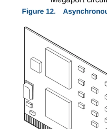
Installing or Replacing Circuit Cards Settings for Optional Circuit CardFigure 12 on page 20 shows the asynchronous SuperSerial circuit card.
Note: If you are installing the asynchronous SuperSerial circuit card, the
system cannot be equipped with the 8-Port Asynchronous Megaport circuit card.
2
Installing or Replacing Circuit Cards Settings for Optional Circuit CardInstalling the Asynchronous SuperSerial Card Driver
To install the asynchronous SuperSerial card driver, do the following:
1 If you are not already logged in as root, do so now.
2 Enter pkgadd -d diskette1
The system displays the following message:
Insert diskette into Floppy Drive 1. Type [go] when ready,
or [q] to quit: (default: go)
3 Insert the diskette labeled “Equinox SST Loadable STREAMS Device Driver (EISA/ISA/MCA/PCI) 1 of 1” into the diskette drive.
4 Press E N T E R.
The system displays the following message:
Installation in progress -- do not remove the diskette.
The following packages are available: 1. eqn Equinox SST Loadable STREAMS
Device Driver (EISA/ISA/MCA/PCI) (i386)
Select package(s) you wish to process (or ‘all’ to process all packages). (default: all) [?,??,q]:
2
Installing or Replacing Circuit Cards Settings for Optional Circuit CardThe system displays the following message:
PROCESSING:
Package: Equinox SST Loadable STREAMS Device Driver (EISA/ISA/MCA/PCI) (eqn) from <diskette1>
Equinox SST Loadable STREAMS Device Driver (EISA/ISA/MCA/PCI) (i386)
Using </> as the package base directory. Lucent Technologies Inc.
The system displays several status messages and then the following message:
This seems to be an ISA system. Is this correct[Y/n]?
6 Enter y
The system displays the following message: Installing for ISA bus system.
2
Installing or Replacing Circuit Cards Settings for Optional Circuit CardThe system displays the following message:
One 16k block of memory addresses will be used by all Equinox ISA boards. This address must meet the following criteria:
1. In the range of 640 kilobyte to 1 Megabyte or above 2 Gigabytes
2. No other physical memory (RAM/ROM) present 3. Must NOT be cached
4. Must begin on a 16k boundary
An example hexadecimal address is 0xb0000
Enter your address selection in hexadecimal: 0x
8 Enter the appropriate address as determined by the Hardware Resource Allocator.
The memory block boundary is determined by the Intuity CONVERSANT Hardware Resource Allocator. See “Hardware Resource Allocator Operation on page 359” in Appendix A, System Configuration.
The system displays the following message:
You may enable a selection of baud rates above 38400 for all ports by answering "Yes" to the following question.
2
Installing or Replacing Circuit Cards Settings for Optional Circuit CardThe high baud rates are selected according to the following table:
57600 B50
76800 B75
115200 B110
238400 B134 (depending on board/module (type
Enable high baud rate selection [y/N]?
9 Enter n
The system displays the following message:
The unix kernel will be rebuilt to include your configuration changes during the next system reboot.
A system rebuild has been requested when the system is shutdown. System tunables have been modified.
Please request a reboot using the "init 6" command to use the driver.
2
Installing or Replacing Circuit Cards Settings for Optional Circuit CardInsert diskette into Floppy Drive 1. Type [go] when ready,
or [q] to quit: (default: go)
10 Enter q
11 Remove the diskette labeled “Equinox SST Loadable STREAMS Device Driver (EISA/ISA/MCA/PCI) 1 of 1” from the diskette drive.
12 Reboot the system. See “Reboot the System,” in “Common System Procedures,” in the Intuity CONVERSANT System Reference, 585-313-205.
PCI Ethernet LAN Circuit Cards
The system supports two versions of the PCI Ethernet LAN circuit card
• SMC8432
• SMC9332
These cards allow you to connect the Intuity CONVERSANT system to your local area network.
SMC8432 Circuit Card
2
Installing or Replacing Circuit Cards Settings for Optional Circuit Card2
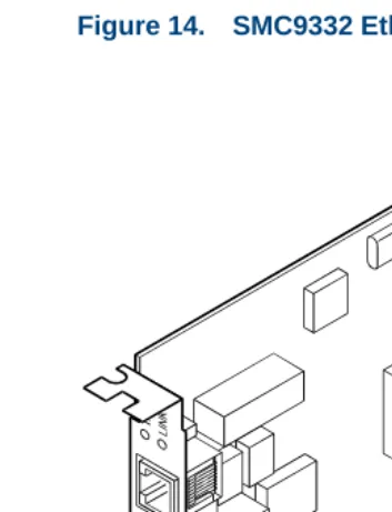
Installing or Replacing Circuit Cards Settings for Optional Circuit CardSMC9332 Circuit Card
The SMC9332 Ethernet LAN circuit card is a 10/100-Mbps circuit card. Figure 14 on page 27 shows the SMC9332 Ethernet LAN circuit card.
Note: There are no jumpers on the SMC9332 circuit card.
2
Installing or Replacing Circuit Cards Settings for Optional Circuit CardInstalling a PCI LAN Circuit Card
Installation of a 10 Mbps or a 10/100 Mbps PCI LAN circuit card, in a system which did not previously have a LAN circuit card, involves
~ Installing a PCI LAN Circuit Card on page 28
~ CMOS Parameter Settings on page 34
~ Installing the PCI Circuit Card Driver on page 30
~ Verifying the PCI LAN Circuit Card Installation on page 33
Installing the PCI LAN Circuit Card
To install either a 10 Mbps or a 10/100 Mbps PCI LAN circuit card, do the following:
1 Shut down the system if it is up and running; otherwise continue with step 2. See “Shut Down the System,” in “Common System Procedures,” in the Intuity CONVERSANT System Reference, 585-313-205.
2 Install the 10 Mbps or 10/100 Mbps PCI LAN circuit card. See Installing a Circuit Card on page 16.
2
Installing or Replacing Circuit Cards Settings for Optional Circuit CardInstalling a 100 Mbps PCI LAN Circuit Card
Note: Perform the following procedure if the SMC9332 circuit card is
required to operate at 100 Mbps. If the SMC9332 circuit card is to operate at 10 Mbps, continue with Installing the PCI Circuit Card Driver on page 30 because no changes are required for 10 Mbps operation.
To ensure the SMC9332 circuit card operates at 100 Mbps, do the following:
1 Login as root.
2 Enter vi /etc/inst/nics/drivers/smpw0
3 Change the line
SMPMEDIA0 SMC_MEDIA_AMD to
SMPMEDIA0 SMC_MEDIA_STP100_UTP100
Note: SMPMEDIA0 is used for the first PCI LAN circuit card. If you
system is using more than one PCI LAN circuit card, change SMPMEDIA1 (for card 2), SMPMEDIA2 (for card 3), or
SMPMEDIA3 (for card 4) as required, to read the same as that entered for SMPMEDIA0.
2
Installing or Replacing Circuit Cards Settings for Optional Circuit CardInstalling the PCI Circuit Card Driver
To install the PCI LAN circuit card driver, do the following:
1 From the network administrator, determine the following:
~ The machine IP address
~ The machine node name
~ The system name
2 If you are not already logged in as root, do so now.
3 Enter niccfg
The system displays the following message:
Setting up the Network Interface Card Support Utility
2
Installing or Replacing Circuit Cards Settings for Optional Circuit CardFigure 15. Network Interface Card Support Utility—Summary Screen
4 Use the down arrow to select: Accept all Entries
Note: If installing from a diskette, select: Install Driver from IHV
Diskette
5 Press E N T E R
The system displays the following message:
Installing drivers for Network Card you selected. This will take a few minutes.
SLOT BUS-NUM BOARD NAME IRQ IO-ADDR MAN-ADDDR DMA
--- --- --- --- --- ---
6 PCI___0 SMC_EtherPower_9332 IO f880-f8ff fedfec00-fedfec7f
Please Select an Option
(*) Accept all Entries ( ) Add an entry for a card
( ) Delete/restore an Entry for a Card ( ) Install Driver from IHV Diskette
( ) Cancel this Utility Without Making Changes
Use the up/down arrow keys to select then press ENTER
2
Installing or Replacing Circuit Cards Settings for Optional Circuit Card6 Enter setuname -n name where name is the machine node name.
7 Enter setuname -s name where name is the system name.
8 Enter cd /etc/net
9 Use the vi editor and enter the machine node name to the hostsfile in each of the following directories:
~ ticlts
~ ticots
~ ticotsord
Note: The machine node name must be entered two times on the same
line, separated by a tab.
10 Enter cd /etc/confnet.d/inet
11 Use the vi editor to edit the interface file.
12 Change the line
2
Installing or Replacing Circuit Cards Settings for Optional Circuit Card14 Enter cd /etc/inet
15 Use the vi editor to edit the config file.
16 Change the line
###4c:/usr/sbin/route::n:add default default_router 1 to:
4c:/usr/sbin/route::y:add default a.b.c.254
where a.b.c. are the first three parts of your IP address. For example, IP address 135.7.50.201 would be changed to 135.7.50.254.
17 Write and exit the file.
18 Continue with Verifying the PCI LAN Circuit Card Installation on page 33.
Verifying the PCI LAN Circuit Card Installation
To set the 10 Mbps or 10/100 Mbps PCI LAN circuit card installation, do the following:
1 Enter /etc/inet/rc.restart
2 Check the message log report for TCP/IP or LAN adapter errors. See Chapter 7, “Peripheral Administration,” Intuity CONVERSANT System
2
Installing or Replacing Circuit Cards Settings for Optional Circuit Card3 Verify that you have network connectivity using the ping command. See Appendix A, “Summary of Commands,” in Intuity CONVERSANT System
Version 7.0 Administration, 585-313-501.
CMOS Parameter Settings
To change the CMOS Pnp/PCI System Configuration for either a 10Mbps or a 10/100Mbps PCI LAN circuit card, do the following:
1 Perform a hard reboot of the system. See “Reboot the System,” in “Common System Procedures,” in the Intuity CONVERSANT System
Reference, 585-313-205.
Note: You must perform a hard reboot to access the CMOS parameter
settings.
2 During the POST, press C O N T R O L A LT E S C. The system displays the following message:
Please standby for SETUP Utility...
2
Installing or Replacing Circuit Cards Settings for Optional Circuit CardFigure 16. BIOS Utility Screen
3 Use the up and down arrows on your keyboard to move through the field selections.
4 Select PnP/PCI System Configuration
5 Press ENTER
6 The system displays the PnP/PCI System Configuration screen (Figure 17 on page 36).
BIOS Utility
Basic System Configuration Advanced System Configuration Power Saving
System Security
2
Installing or Replacing Circuit Cards Settings for Optional Circuit CardFigure 17. PnP/PCI System Configuration Screen
7 Use the up and down arrows on your keyboard to move through the field selections.
PnP/PCI System Configuration
PCI IRQ Setting - - - -[manual]
INTA INTB INTC INTD
PCI Slot 1 [14]
PCI Slot 2 [14]
PCI Slot 3 [14]
On-Board VGA [- -]
2
Installing or Replacing Circuit Cards Settings for Optional Circuit Card10 Select the IRQ setting specified in the Hardware Resource Allocater.
11 Press ESC
The system redisplays the BIOS Utility screen (Figure 16 on page 35).
12 Press ESC
The system displays the following:
Do you want to save CMOS data?
[YES] [NO]
13 Use the left and right arrows on your keyboard to move through the field selections.
14 Select [YES]
15 Press ENTER
The system automatically reboots.
Replacing a PCI LAN Circuit Card
To replace a 10Mbps or a 10/100Mbps PCI LAN circuit card, do the following:
2
Installing or Replacing Circuit Cards Settings for Optional Circuit Card2 Record the output.
3 Complete the procedure in Installing a PCI LAN Circuit Card on page 28.
4 Complete the procedure in Verifying the PCI LAN Circuit Card Installation on page 33.
FIFO/SIB Synchronous Host Circuit Card
2
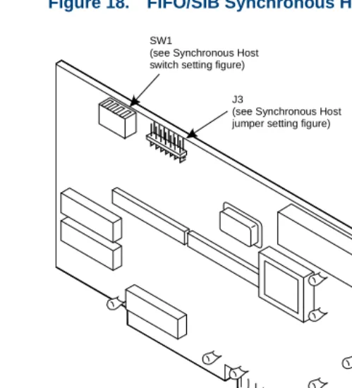
Installing or Replacing Circuit Cards Settings for Optional Circuit CardFigure 18. FIFO/SIB Synchronous Host Circuit Card
SW1
(see Synchronous Host switch setting figure)
J3
(see Synchronous Host jumper setting figure)
J2
2
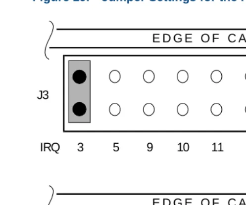
Installing or Replacing Circuit Cards Settings for Optional Circuit CardJumper Settings There are two jumper locations on the synchronous host circuit card, J3 and J2.
Use J3 to set the interrupt request line (IRQ) to a value of 3, 5, 9, 10, 11, 12, or 13 (Figure 19 on page 41). The IRQ corresponds to the number below the pins. Figure 19 on page 41 shows the card set with an IRQ of 3. See
Hardware Resource Allocator Operation on page 359 in Appendix A, System Configuration, for more information.
Note: If you are using IRQ 9, ensure that IRQ 2 is unused on your
system.
J2 is preset at the factory. However, before you install the FIFO/SIB synchronous host circuit card, ensure that this jumper is set as shown in Figure 19 on page 41.
Note: When operating at 64 kbaud, this setting supports a maximum
2
Installing or Replacing Circuit Cards Settings for Optional Circuit CardFigure 19. Jumper Settings for the FIFO/SIB Synchronous Host Circuit Card
Switch Settings Figure 18 on page 39 shows the location of the I/O switch block SW1. Figure 20 on page 42 shows the I/O switch settings for an address of 380.
J3
J2
E D G E O F C A R D
E D G E O F C A R D
2
1
16
15
2
Installing or Replacing Circuit Cards Settings for Optional Circuit CardFigure 20. Switch Settings for the FIFO/SIB Synchronous Host Circuit Card
Table 1 on page 43 shows the switch settings for other potential I/O addresses.
Base I/O address = 380 Hex
All switches closed or OFF
2
Installing or Replacing Circuit Cards Settings for Optional Circuit CardRemote Maintenance Circuit Card
The remote maintenance circuit card provides remote diagnostics of basic components (Figure 21 on page 44). There is one remote maintenance circuit card installed on the system.
Table 1. FIFO/SIB Switch Settings
Switch
I/O Address 1 2 3
250 On On Off
260 Off Off On
2B0 On Off On
2E0 Off On On
380 (default) Off Off Off
3A0 On Off Off
3E0 Off On Off
2
Installing or Replacing Circuit Cards Settings for Optional Circuit CardFigure 21. Remote Maintenance Circuit Card
UPS connector Fan status connector BEC
enable switch Platform
reset connector Factory
2
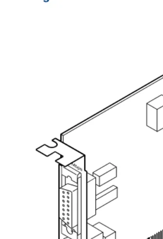
Installing or Replacing Circuit Cards Settings for Optional Circuit CardTypes of Remote Maintenance Circuit Cards
The Lucent Intuity CONVERSANT system supports the AYC54 remote maintenance circuit card:
• With an internal modem (AYC54)
• Without an internal modem (AYC55)
You can determine the type of remote maintenance circuit card installed on you system by viewing the faceplate. Figure 22 on page 46 shows the faceplate of a remote maintenance circuit card with an internal modem (AYC54).
Note: The AYC54 and AYC55 remote maintenance circuit cards can be
2
Installing or Replacing Circuit Cards Settings for Optional Circuit CardFigure 22. AYC54 Remote Maintenance Circuit Card Faceplate
Lock-down screws
RMB reset switch RJ-11 tip-ring connector (line in)
User-definable output
2
Installing or Replacing Circuit Cards Settings f