A METHOD FOR SELECTING SOFTWARE FOR DYNAMIC EVENT
ANALYSIS I: PROBLEM SELECTION
J. M. Lacy, S. R. Novascone, W. D. Richins, T. K. Larson Idaho National Laboratory, Idaho Falls, ID
ABSTRACT
New nuclear power reactor designs will likely require resistance to a variety of possible malevolent attacks, as well as traditional dynamic accident scenarios. The design/analysis team may be faced with a broad range of phenomena including air and ground blasts, high-velocity penetrators or shaped charges, and vehicle or aircraft impacts. With a host of software tools available to address these high-energy events, the analysis team must evaluate and select the software most appropriate for their particular set of problems. The accuracy of the selected software should then be validated with respect to the phenomena governing the interaction of the threat and structure. In this paper, we present a method for systematically comparing current high-energy physics codes for specific applications in new reactor design.
Several hydro codes are available for the study of blast, impact, and other shock phenomena. Historically, these packages were developed to study specific phenomena such as explosives performance, penetrator/target interaction, or accidental impacts. As developers generalize the capabilities of their software, legacy biases and assumptions can remain that could affect the applicability of the code to other processes and phenomena. R&D institutions generally adopt one or two software packages and use them almost exclusively, performing benchmarks on a single-problem basis. At the Idaho National Laboratory (INL), new comparative information was desired to permit researchers to select the best code for a particular application by matching its characteristics to the physics, materials, and rate scale (or scales) representing the problem at hand. A study was undertaken to investigate the comparative characteristics of a group of shock and high-strain rate physics codes including ABAQUS, LS-DYNA, CTH, ALEGRA, ALE-3D, and RADIOSS.
A series of benchmark problems were identified to exercise the features and capabilities of the subject software. To be useful, benchmark problems require several features. They should be; 1) small, requiring reasonable computer resources, 2) designed to engage a small set of physical phenomena, 3) independent of code formulation, 4) verifiable, either by closed-form solution or experimental result, and 5) unlimited in distribution. This paper presents the selection rationale and problems chosen for the benchmarking suite exhibiting the above features. Detailed discussion of the benchmark study results will be presented in future reports.
INTRODUCTION
The revived interest in nuclear reactor technology is spurring research into new processes and materials to meet aggressive performance goals. Programs such as the Next Generation Nuclear Plant[1] and Global Nuclear Energy Partnership[2] are driving the development of new technologies to achieve higher levels of operational performance and safety than ever before. At the same time the safety analyses of these new reactor systems will need to address a broad range of malevolent attacks and dynamic accidents. Potential attackers have a wide variety of tools which they may direct at a high-visibility, high-consequence target such as a nuclear power facility, including vehicles, aircraft, high explosives, ballistic penetrators, explosively formed projectiles, and shaped charges.
Solid dynamics/shock physics software (hydro codes) that simulate a subset of the possible attacks on various elements of the reactor plant system are likely to be employed in the design stages of next generation nuclear facilities. Given the plethora of such software currently available, the designers’ first hard problem will be to choose the best simulation software for the job. A comparison of software qualities among the different software products would appear to be the most obvious method to select the best tool.
A review of the literature indicates that no such comparisons exist. While there are a multitude of reports involving the use of more than one simulation software product to simulate an event, the scope is too narrow both in application and software to address the design engineer’s question “which is best for my circumstance?”
This INL project is in the first year of a 3-year effort to develop and implement a comparative study of a broad group of solid dynamics and shock physics simulation codes. Our objectives are to develop a manageably small yet broadly representative benchmarking suite and apply it to a large fraction of the software available. We will report on usability, suitability to the class of problem, computational efficiency, and accuracy. In this paper, we discuss our method for selecting a benchmarking problem suite, the problems that make up the suite, and some preliminary results from a subset of codes. Complete results of the benchmarking study will be published in the future.
SOFTWARE EMPLOYED
A very brief overview of the shock and high-strain rate physics codes used (or to be used) in this study is provided in this section with information essentially extracted from various user and theory manuals. This code group is not intended to be exhaustive and simply represents software accessible to the authors for reasons related to software license access/availability, code application expertise, and/or funding limits.
ABAQUS[3] is a suite of engineering simulation programs, based on the finite element method, that can solve problems ranging from relatively simple linear analyses to challenging nonlinear simulations. Material models for simulation of engineering materials including metals, rubber, polymers, composites, reinforced concrete, crushable and resilient foams, and geotechnical materials (soils and rock) are available. ABAQUS is a general-purpose tool that can be used to study structural as well as heat transfer, mass diffusion, thermal management, acoustics, and soil mechanics problems. In most simulations, including highly nonlinear ones, the user need only provide the engineering data (structure geometry, material behavior, boundary conditions, applied loads) and ABAQUS automatically chooses appropriate load increments and convergence tolerances and continually adjusts these parameters during the analysis to ensure accurate solutions. ABAQUS runs on a variety of desktop workstations and clusters.
LS-DYNA[4] is a general purpose finite element code for analyzing the large deformation dynamic response of structures including structures coupled to fluids. The main solution methodology is based on explicit integration although an implicit solver is available with somewhat limited capabilities including structural analysis and heat transfer. Contact-impact algorithms allow difficult contact problems to be easily treated with heat transfer included across the contact interfaces. Spatial discretization is achieved by the use of rigid bodies and a large variety of element types and formulations. Specialized capabilities exist for automotive applications. Adaptive re-meshing is available for shell elements. LS-DYNA currently contains approximately one-hundred constitutive models and ten equations-of-state for material behavior. LS-DYNA is operational on a large number of mainframes, workstations, massively parallel processor (MPP) supercomputers, and personal computers.
CTH[5]is a multi-material, large deformation, strong shock wave, solid mechanics code for modeling complex multi-dimensional problems characterized by large deformations and/or strong shocks. CTH has models for material strength (elastic and viscoplastic or rate-dependent), fracture, porous materials, and high explosive detonation and initiation. Three-dimensional rectangular meshes; two-Three-dimensional rectangular and cylindrical meshes; and one-Three-dimensional rectilinear, cylindrical, and spherical meshes are available. CTH uses a two-step, second-order accurate Eulerian solution algorithm to solve the mass, momentum and energy conservation equations to reduce dispersion and dissipation and produce accurate, efficient results. CTH runs on most UNIX workstations, MPP supercomputers, and Intel Windows NT workstations.
ALEGRA[6] is an arbitrary Lagrangian-Eulerian (ALE) multi-material finite element code that is used for modeling solid dynamics problems involving large distortion or deformation and strong shock physics/shock propagation. ALEGRA contains elements of CTH in an effort to combine the features of Eulerian shock codes with the improved numerical accuracy of Lagrangian finite element codes. This capability permits a calculation to proceed in Lagrangian fashion until portions of the finite element mesh become too distorted, at which time the nodal points in the most deformed portion of the mesh are moved to reduce the distortion to acceptable levels thereby avoiding numerical dissipation. In addition to mesh smoothing, the ALEGRA remesh algorithm can also move nodes to better resolve mesh regions with specific values of selected variables or their gradients. ALEGRA runs on MPP computers using domain decomposition to take advantage of large memory and processor speed attributes for analyzing large, 3D problems.
ALE 3D[7]is an arbitrary-Lagrange-Eulerian, finite element code that treats fluid and elastic-plastic response of materials on an unstructured grid. While the code was ‘born 3D’, recently much of the functionality has been converted to 2D plane strain and axisymmetric geometries. The most mature physics components of the code are explicit and implicit continuum-mechanics, thermal diffusion, and chemistry. Incompressible flow, multiphase flow, and magneto-hydrodynamic models also exist. All components of the code participate in advection (mesh modification to alleviate tangling or to preserve an Eulerian grid) and all of the mature capabilities operate with slide surfaces (boundaries between disjoint sections of the grid). The unstructured grid is composed of arbitrarily connected 3D hexagonal elements and shell and beam structural elements can couple to 3D elements. ALE 3D runs on a variety of Unix/Linux and Windows desktop computers and massively parallel processor supercomputers.
RADIOSS[8] is a transient explicit and implicit finite-element solver technology that simulates mechanical, structural, fluid and fluid-structure interaction phenomena, taking into account nonlinear material, for quasi-static and dynamic loading events. RADIOSS allows simulation of complex problems, such as safety-related performance, impact events, stamping, forming, aero-acoustics, structural wave propagation, biomechanics, and fluid and fluid-structure interactions. RADIOSS is part of the Altair® HyperWorks® CAE technology suite which provides solver solutions for linear, nonlinear, fluid and fluid structure interaction, structural optimization and multi-body dynamics applications, and visualization and process automation solutions. RADIOSS SPMD V5 runs on Linux clusters and in the Windows Server 2003 environment.
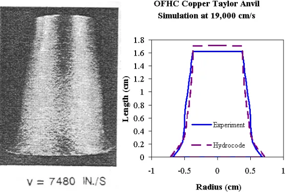
Figure 1. Experiment and simulation (CTH) of a Taylor Rod Impact, OFHC copper
BENCHMARK PROBLEM SELECTION
Literally hundreds of possible benchmarking problems are available, addressing broad ranges of physics, material interactions, size, and complexity pertinent to the structural dynamics application envisioned. Most of the software evaluated is distributed with tens, if not hundreds, of example, validation, and benchmarking problems developed over time from the developers’ experience. Several relevant problems can be found in the literature as well. Given the overwhelming variety of choices, a priority was to select a manageably small subset of problems to focus on, with the goal that the subset would address the major capabilities of the software, while representing the types of problems likely to be presented to reactor plant designers. A selection criteria was developed to guide the search and add consistency to the selection process. These criteria require that the problems be; 1) relatively uncomplicated, so that they may be coded and run in a realistic quantity of time, 2) designed to engage a limited set of physical phenomena per problem, so that the source of any differences in results may be more easily identified, 3) independent of the code formulation (Eulerian/Lagrangian/Smooth Particle Hydrodynamics (SPH)/etc.) for broad applicability, 4) verifiable, either by closed-form solution or experimental result, and 5) unlimited in distribution, so that results may be compared among institutions with different computing hardware resources. In the following sections, five problems are presented that together meet a majority of these criteria. Figures of merit are discussed for each problem to quantify the accuracy of a code, comparing tests or closed form solutions with simulation results.
PROBLEM DESCRIPTIONS Taylor Anvil Test
The Taylor anvil test was first developed by Taylor[9] as a method to determine the dynamic yield stress of idealized materials. The test specimen is a right circular cylinder of the subject material, which is impacted against a theoretically rigid target e.g., an anvil. Taylor derived a method to determine the dynamic yield stress from measurements of initial velocity, impact velocity, and undeformed specimen length. Strain rates for this test can be as high as 103 s-1[10]. For the sake of brevity, the derivation is not presented here, however an excellent presentation is made by Zukas[11]. Taylor’s 1-dimensional derivation has been modified and extended several times to include elastic strains, non-linear work hardening, and non-rigid targets[12].
The practical use of the Taylor Anvil test is somewhat narrow because the stress-state is not uniform and the total-strain at the center of the specimen is only to about 0.6[13]. The test, therefore, is used chiefly to validate constitutive models in numerical simulation by direct comparison of the experimental final deformed rod shape to computational predictions. The final deformed shape depends upon the dynamic yield stress, strain hardening, and adiabatic deformation heating, which in turn depend on strain and strain rate fields that vary both temporally and spatially in the specimen. Taylor impact simulations are also used to evaluate modeling features such as rigid and symmetric boundary conditions, plastic wave propagation, and large element distortion.
A numerical model of a Taylor rod was developed to compare results among simulation codes and experimental measurements (Figure 1). The numerical codes used thus far were CTH, LS-DYNA (Lagrangian/SPH), and ABAQUS. The dimensions of the model of the Taylor rod were 2.54 cm in length and 0.384 cm in radius. A Johnson-Cook material strength model[10] for oxygen-free high-conductivity (OFHC) copper was chosen for the numerical simulation. The Taylor rod (simulation and experiment) impacted a rigid target at speeds of 130, 146, and 190 m/s. The figures of merit compare the final length and diameter to the original length and diameter of the Taylor rod.
predicted final diameter and length of the impact specimens. ALEGRA, ABAQUS, and LS-DYNA results were nearly identical to those shown for CTH. None of the hydro codes calculated the plastic bulge that can be seen in the middle section of the impact bar that can be seen in the photo and experiment measurements of Figure 1. Future work regarding modeling and simulation of the Taylor impact shall include contact with a non-rigid surface, fracture material models, ALE for re-meshing of highly distorted elements, and the remaining software codes.
Free Air Blast
The problem of explosive loadings on structures has long been of concern to national security and military-related sectors, and has new relevance in the civilian sector. In order to predict the response of the system of interest to a blast, very often the blast itself must be simulated in its entirety in order to produce a load history of acceptable accuracy.
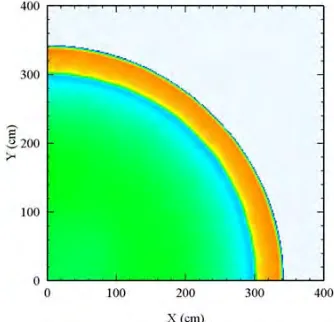
While explosive weapons proliferate in a confounding variety of materials, combinations, and geometric configurations, a simple benchmark may be employed to exercise the phenomena of the high explosive burn and expansion in air. A bare spherical charge of a well-characterized high-explosive is surrounded by air at standard conditions, remote from any solid surfaces. The charge is initiated from its geometric center and allowed to expand into the surrounding air (Figure 2). The velocity, intensity, and duration of the expanding pressure wave may be calculated and compared to empirical data such as that shown in Figure 3. This problem allows us to examine how a software code treats high explosive burn models; equations of state for explosives, explosive products, and air; material advection through the computational domain; and the propagation and decay of the shock wave.
Bare spherical charges and the shocks they produce have been extensively studied both analytically and experimentally. Analytical solutions for the properties of the blast wave front were first developed by Rankine and Hugoniot in 1870[14], with results compiled both graphically[15] and analytically[16][17][18].
Because the air blast problem is geometrically spherical, it lends itself well to comparisons of 1-D spherical, 2-D cylindrical, and 3-D rectangular domain geometries. Three-dimensional geometries may also be subdivided into a half-, quarter-, or eighth- (or more) subspace as a test of boundary performance. Figures of merit for this problem include peak pressure as a function of distance from the charge, spatial pressure profile at a given time, and the time of arrival of the pressure pulse at a given location. Valuable extensions to the problem include the addition of a ground surface to generate a mach stem in the pressure wave, the addition of a casing to the charge to investigate the effects of initial confinement, and modifications to the geometry of the charge and initiator.
Split Hopkinson Pressure Bar
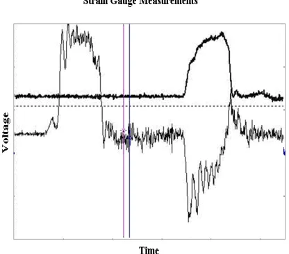
Measurement of the dynamic stress-strain response of materials at strain rates of up to 104 s-1 is achieved through the use of the split-Hopkinson pressure bar (SHPB) apparatus[19]. Figure 4 shows the embodiment of a split-Hopkinson pressure bar. A striker bar impacts the end of one of the long bars, which transmits the imparted stress wave through both the sample and the bar on the other side of the sample. Ideally, the waves traveling through the bars are elastic and the deformation of the sample is uniform plastic flow. Strain gauges on each bar record the incident, reflected, and transmitted elastic waves. The stress and strain can be calculated from the measurements of the transmitted and reflected waves respectively. These calculations result in a true-stress true-strain dynamic flow stress curve.
Figure 2. Simple 2-D CTH blast simulation, showing shock (orange) and rarefaction (blue) waves in air (INL simulation)
1 10 100
0.1 1 10 100 1.103
Peak Static Overpressure Peak Dynamic pressure Peak Static Overpressure Peak Dynamic pressure
Scaled Distance (m/kg^1/3)
Pressure (kPa)
Figure 3. Traces of peak static and dynamic pressures vs. scaled distance (closed form solution)[17]
As an example, the application of LS-DYNA to this problem is presented briefly. The Lagrangian formulation of LS-DYNA was used for this simulation. Pressure bars were 120.7 cm in length and 1.22 cm in diameter. The sample was 0.635 cm in length and 0.914 cm in diameter. The impact bar was 0.914 cm in diameter and 10 cm long. The reaction mass was 1.92 cm in diameter and 2.97 cm long. An initial velocity of 400 cm/s was prescribed as an initial condition to the impact bar in the direction of the adjacent pressure bar. The pressure bars,
sample, and reaction mass were free of constraints except for contact. The pressure bars were 4340 steel. The sample was 6061 aluminum. The Johnson-Cook[10] constitutive model was employed for the sample, while the pressure bars were modeled as linear-elastic. The figure of merit for this simulation is the uniformity of deformation in the sample and comparison of the incident, reflected, and transmitted wave forms to those from analogous experiments. The simulation description and results are summarized in Figures 5 and 6 comparing explicit finite element calculations (friction included) with strain gauge voltage readings from a typical split-Hopkinson pressure bar experiment, respectively. Figures 5 and 6 indicate that the numerical solution is tracking physical phenomena such as elastic and plastic wave propagation and flow, conservation of energy and momentum, and finite element contact.
Dynamic Splitting and Crushing of a Concrete Cylinder
Because significant components of a nuclear reactor plant, such as the containment, are made of concrete, the dynamic analysis software employed must have the ability to simulate the dynamic failure of concrete as well as its elastic properties. Therefore it was determined that at least one of the benchmark problems should address the response of concrete to impact loading. The splitting-tensile test (also known as the Brazilian test) subjects a concrete cylinder to diametric compression which according to elastic theory induces a nearly uniform tensile stress field perpendicular to the line of loading. There is an ASTM standard[20] for the test at quasi-static load rates, and a useful quantity of discussion in the literature addressing the dynamic event both experimentally and numerically.
The dynamic response of concrete under impact or blast loads is governed by the nucleation and growth of complex fracture patterns through the material[21]. The scale and pattern of the cracks formed, and thus the quantity and time scale of the energy absorbed, are functions of the loading rate and geometric scale of the body. Strength and fracture energy have been demonstrated to both increase sharply at high loading rates[22][23][24]. Development of methods by which this complex behavior may be accurately predicted has been the subject of extensive investigation for several years. Common methods include direct compression or direct tension via SHPB, and splitting tensile strength (Brazilian test) by SHPB. Modifications include the addition of lateral confining pressure, or the use of drop-weight devices instead of the Hopkinson bar[25].
Figure 4. Embodiment of split-Hopkinson pressure bar
Finite Element Strain Calculations
-0.0008 -0.0004 0 0.0004 0.0008 0.0012
0 0.0001 0.0002 0.0003 0.0004 0.0005
Time (sec)
St
rai
n
Incident and Reflected Transmitted
Figure 5. Finite element calculations of strain in a split-Hopkinson experiment (INL simulation)
Figure 6. Typical strain gauge measurements from a split-Hopkinson pressure bar (INL data)
Direct tension tests using the SHPB typically achieve strain rates from 10-1 to 101 s-1[23][25], although rates to 103 have been reported[26]. To achieve higher strain rates, the Hopkinson bar may be used in a spalling configuration, wherein the transmitted bar is removed, causing the incident (compressive) stress wave to reflect off the free end of the concrete specimen as a tensile wave. Klepaczko and Brara[27] performed a large series of experiments investigating the relationship of strength and strain rate for both wet and dry concrete. Schuler et al[23] extended that work to include the specific fracture energy which was shown to increase by a factor between 2 and 3 at strain rates near 10 s-1. This approach is appealing because of the simplicity of both the geometry and load modeling, and the single-phenomenon material response (uniaxial tensile fracture).
Direct compression tests are also employed with some success to characterize the high-rate response of concrete. Strain rates to 104 s-1 have been achieved in compression[24]. Tedesco et al[28] report results of numerical simulation of direct compression test in a SHPB apparatus.
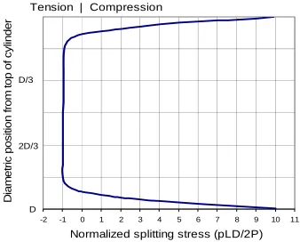
The splitting tension test, or Brazilian test, differs from the direct tension and compression tests in that the specimen is loaded diametrically in compression, rather than axially. A schematic of the test setup is shown in Figure 7. The quasi-static method is described in ASTM[20]. A concrete cylinder is compressed on its diameter between two bearing strips of width 1/12 the diameter of the cylinder. To generate a high-rate load, a SHPB is often employed. Hughes et al[22] established that stress distribution in dynamic tests follows the classic elastic description.
This stress field (Figure 8) produces a fracture at the center of the specimen that propagates toward the loading points until the cylinder is split. Small zones of crushing failure are also observed near the supports[21]. This fracture and crushing response is difficult to address with classical finite element methods, and most investigators develop their own material models, finite elements, or both. For the purposes of this study, we will only employ elements and material models distributed with the software to investigate their off-the-shelf capabilities.
Possible extensions and enhancements to this problem include incorporating a notched cavity along the axis of the cylindrical specimen order to produce pure mode-I failure, following Lambert and Ross[29]. As with the un-notched specimen, they showed fracture toughness and strength increase significantly with loading rate. They provide enough experimental data to develop figures of merit for a numerical study, such as measured strength, fracture energy, and the load-rate dependence of both.
Rieder and Mindess[25] proposed another method for evaluating the impact response of concrete employing a biaxial compression device coupled with a drop-weight impact-testing machine. The impact and support heads were shaped to produce line loads on the top and bottom specimen faces resulting in a splitting failure similar to that produced by the Brazilian test. They report sufficient data to numerically reproduce time-histories of the impact force and confinement forces for a variety of pre-stress states and impact velocities.
Concrete Penetration by a Projectile
Concrete structures critical to a nuclear reactor plant are typically required to resist impact loads from a variety of potential missiles including tornado-driven projectiles, turbine blade fragments, impacting aircraft engines, and small arms. Since full-scale testing of projectile impacts into concrete targets for specific applications is generally cost prohibitive, empirical formulas extrapolated from limited test data have historically been used to estimate impact effects for each potential missile, concrete type, impact velocity, and impact angle combination. Impact effects of a projectile on a plain or
Figure 7. 2-dimensional schematic of Brazilian splitting test
-2 -1 0 1 2 3 4 5 6 7 8 9 10 11
Normalized splitting stress (pLD/2P)
D
iam
et
ri
c
p
os
it
ion f
rom
t
op of
c
y
lin
de
r
Tension | Compression
D/3
2D/3
D
Figure 8. Distribution of horizontal stress along diameter of tensile-splitting specimen
reinforced concrete target include concrete spalling at the impact surface, projectile penetration into the concrete, scabbing on the rear surface, and potential projectile perforation through the concrete. These phenomena, especially predictions of penetration and perforation, can now be evaluated using shock and high-strain rate physics codes calibrated using test results.
Quality test data using ogive-nosed projectiles is available from several sources. Li and Tong[30] summarize test data and empirical formulas. Forrestal et al[31] present penetration data for a 26.9 mm diameter 0.90 kg projectile impacting plain concrete targets with unconfined compressive strength (f’c) of 36 MPa (5ksi) at velocities of 277 to 900 m/s.
Perforation data is available for reinforced concrete targets with f’c of 48 MPa (7 ksi) and 140 MPa (20 ksi) using a 25.4 mm
diameter 0.50 kg projectile[32]. Test results typically include projectile striking velocity and orientation, penetration depth or residual velocity if the projectile perforated the target, and standard concrete triaxial material test data. In general, the test results lack the quantitative spalling or scabbing measurements necessary to compare with modeling and simulation results.
Recent papers describing simulation techniques used to predict concrete response to projectile impact are also available. Tai and Tang[33] modeled the Hanchak et al[32] tests using LS-DYNA and compared simulation predictions with the test data. Tham[34] used Langrange, Euler-Langrange coupling, and SPH methods to predict penetration depth and radial stress versus time response of the concrete target.
We chose to create a benchmark problem simulating tests from Forrestal et al[31] with a 0.90 kg projectile penetrating but not perforating a 1.22 m x 1.37 m diameter cylindrical plain concrete target. These tests have accurately determined striking velocities, orientations, and concrete material data. Eliminating rebar in the target greatly simplifies the model and allows for a more direct comparison of concrete penetration simulation results between codes. The figure of merit for this simulation is the comparison of projectile penetration and energy conservation. This benchmark evaluates the ability of the codes to predict penetration in a complex material (concrete in this case), use rate dependent material properties, and to estimate energy dissipation during the penetration event. This benchmark problem could be expanded to include perforation prediction, evaluate the degree of spalling and scabbing (volume, size, and velocity of debris), and address the influence of various concrete fiber additives or external fiber wrap.
CONCLUSIONS
A small group of solid dynamics and shock physics problems for use as a comparative benchmarking suite for evaluating dynamic event analysis software were presented. These problems model physical phenomena representative of design challenges such as air and ground blasts, high-velocity penetrators or shaped charges, and vehicle or aircraft impacts for new nuclear power facilities. Problem selection criteria were; 1) relatively uncomplicated, so that they may be coded and run in a realistic quantity of time, 2) designed to engage a limited set of physical phenomena per problem, 3) independent of the code formulation (Eulerian/Lagrangian/SPH/etc.), 4) verifiable, either by closed-form solution or experimental result, and 5) unlimited in distribution. Six currently available relevant software packages are being compared with respect to suitability to the class of problem and accuracy using the figures of merit discussed in this paper.
Results to date indicate the problems identified are suitable for numerical simulation and are well-supported by experimental and/or analytical characterizations. For example, simulation results for the Taylor Rod problem with CTH, ALEGRA, LS-DYNA, and ABAQUS show good agreement with each other but differ in some aspects with the test data. Also, LS-DYNA simulation of the split-Hopkinson bar apparatus compares well with test results.
Conclusions from comparisons of these codes as to the individual application of specific software to specific problems shall be presented in a follow-up publication. Additional problems may be necessary to fill physics or material behavior gaps, such as high strain-rate sheet metal deformation in vehicle impacts and fluid-structure interactions.
REFERENCES
1. Idaho National Engineering and Environmental Laboratory Report, Design Features and Technology Uncertainties for the Next Generation Nuclear Plant,, INEEL/EXT-04-01816, June 2004.
2. U.S. Department of Energy, Office of Nuclear Energy, Office of Fuel Cycle Management, Global Nuclear Energy Partnership Strategic Plan, GNEP-167312, Rev. 0, January 2007.
3. ABAQUS, Getting Started with ABAQUS Version 6.6, ABAQUS, Inc. 2006.
4. Hallquist, J. O., LS-DYNA Theory Manual, Livermore Software Technology Corporation, Livermore, CA, 2006.
5. McGlaun, J. M., S. L. Thompson, and M. G. Elrick, A Brief Description of the Three-Dimensional Shock Wave Physics Code CTH, Technical report SAND89-0607, Sandia National Laboratories, Albuquerque, NM, 1989.
6. Carroll, S. K. et. al., ALEGRA:Version4.6 (Revised), Sandia National Laboratory report, SAND2005-draft, 2005. 7. Nichols, Albert L. III (Ed.), Users Manual for ALE 3D, An Arbitrary Lagrange/Eulerian 3D Code System, Volume 1,
9. Taylor, G. I., “The Use of Flat Ended Projectiles for Determining Yield Stress, Part I: Theoretical Considerations,”
Proceedings of the Royal Society (London), Vol. 194, 1948, p. 289-299.
10. Johnson, G. R., and Cook, W. H., “A Constitutive Model and Data for Metals Subjected to Large Strains, High Strain Rates and High Temperatures,” Proceedings of the Seventh International Symposium on Ballistics (The Hague), ADPA, pp. 541-547, 1983.
11. Zukas, J. A., Introduction to Hydrocodes, Elsevier, Amsterdam, 2004.
12. Recht, R. F., “Taylor Ballistic Impact Modeling Applied to Deformation and Mass Loss Determinations,” Int. J. Eng. Sci., Vol. 16, pp. 809-827, 1978.
13. Banerjee, B., “An Evaluation of Plastic Flow Stress Models for the Simulation of High-Temperature and High-Strain-Rate Deformation of Metals,” working paper, 2006.
14. Rankine, W. J. M., “On the Thermodynamic Theory of Waves of Finite Longitudinal Disturbance,” Phil. Trans. Royal Soc., 1870, 160, pp. 277-288.
15. Soroka, B., Air Blast Tables for Spherical 50/50 Pentolite Charges at Side-on and Normal Incidence, BRL-R-1092, Dec. 1979.
16. Brode, H. L., “Numerical Solution of Spherical Blast Waves,” J. App. Phys., No. 6, 1955.
17. Mays, G. C., Smith, P. D. Ed., Blast Effects on Buildings, Thomas Telford Publications, London, 1995. 18. Cooper, P. W. Explosives Engineering, Wiley-Vch, New York, 1996.
19. G. T. Gray, III, “Classic Split Hopkinson Pressure Bar Technique,” ASM Handbook Vol. 8: Mechanical Testing and Evaluation, ASM International, 2000, p. 462-476.
20. ASTM International, Standard Test Method for Splitting Tensile Strength of Cylindrical Concrete Specimens, C 496/C 496M-04, 2004.
21. Ruiz, G., Ortiz, M., and Pandolfi, A., “Three-Dimensional Finite-Element Simulation of the Dynamic Brazilian Tests on Concrete Cylinders,” Int. J. Numer. Meth. Engng., Vol. 48, pp. 963-994, 2000.
22. Hughes, M. L., Tedesco, J. W., and Ross, C. A., Numerical Analysis of High Strain Rate Splitting-Tensile Tests,”
Computers and Structures, Vol. 47, No. 4/5, pp. 653-671, 1993.
23. Schuler, H. Mayrhofer, C., and Thoma, K., “Spall Experiments for the Measurement of the Tensile Strength and Fracture Energy of Concrete at High Strain Rates,” Int. J. Impact Eng., Vol. 32, pp. 1635-1650, 2006.
24. Grote, D. L., Park, S. W., and Zhou, M., “Dynamic Behavior of Concrete at High Strain Rates and Pressures: I. Experimental Characterization,” Int. J. Impact Eng., Vol. 25, pp. 869-886, 2001.
25. Rieder, K. A., and Mindess, S. “New Test Method to Evaluate the Impact Behavior of Biaxially Confined Concrete,”
Materials and Structures, Vol. 31, December 1998, pp. 669-675.
26. Tedesco, J. W., Ross, C. A., McGill, P. B., and O’Neil, B. P., “Numerical Analysis of High Strain Rate Concrete Direct Tensions Tests,” Computers and Structures, Vol 40, No. 2, pp 313-327, 1991.
27. Klepaczko, J. R., and Brara, A., “An Experimental Method for Dynamic Tensile Testing of Concrete by Spalling,” Int. J. Impact Engng., Vol. 25, No. 4, pp. 387-409, 2001.
28. Tedesco, J. W., Hughes, M. L., and Ross, C. A., “Numerical Simulation of High Strain Rate Concrete Compression Tests,” Computers and Structures, Vol. 51, No. 1., pp. 65-77, 1994.
29. Lambert, D. E., and Ross, C. A., “Strain Rate Effects on Dynamic Fracture and Strength,” Int. J. Impact Eng. Vol. 24, pp. 985-998, 2000.
30. Li, Q. M. and Tong, D. J., “Perforation Thickness and Ballistic Limit of Concrete Target Subjected to Rigid Projectile Impact,” J. Eng. Mechanics, Vol. 129, pp 1083-1091, 2003.
31. Forrestal, M. J., Altman, B. S., Cargile, J. D., and Hanchak, S. J., “An Empirical Equation for Penetration Depth of Ogive-Nose Projectiles Into Concrete Targets,” Int. J. Impact Eng., Vol. 15, pp. 395–405, 1994.
32. Hanchak, S. J., Forrestal, M.J., Young, E.R., and Ehrgott, J.Q., “Perforation of Concrete Slabs with 48 MPa (7 ksi) and 140 MPa (20 ksi) Unconfined Compressive Strengths,” Int. J. Impact Eng., Vol. 12, pp. 1–7, 1992.
33. Tai, Y. S. and Tang, C. C., “Numerical Simulation: The dynamic Behavior of Reinforced Concrete Plates Under Normal Impact," Theoretical and Applied Fracture Mechanics, Vol. 45, pp. 117-127, 2006.
34. Tham, C. Y., “Numerical and Empirical Approach in Predicting the Penetration of a Concrete Target by an Ogive-Nosed Projectile,” Finite Elements in Analysis and Design, Vol. 42, pp 1258-1268, 2006.