Unified Messaging
Voice Mail System
Installation and Programming
Manual
2003 Aleen Technologies All rights reserved.
The information disclosed herein is proprietary to Aleen Technologies and may not be sold, transferred or copied without the written consent of Aleen Technologies.
Contents
1
Introduction ... 1-1
1.1
Manual Audience and Contents... 1-1
1.2
Manual Conventions ... 1-1
1.3
System Description ... 1-2
1.3.1
Functional Description ... 1-2
1.3.2
Physical Description... 1-10
1.3.3
Technical Data ... 1-11
1.4
Workflow ... 1-13
2
Installation ... 2-1
2.1
Unpacking ... 2-1
2.2
Hardware Installation ... 2-2
2.2.1
Voice Mail System Installation ... 2-3
2.2.2
Connections, Starting Up and Initial Indications ... 2-4
2.2.3
Physical Expansion... 2-5
2.3
Software Setup ... 2-6
2.3.1
Installing the VUP Software ... 2-7
2.3.2
PBX Selection ... 2-8
2.3.3
Configuring the VUP Toolbars ... 2-8
2.3.4
Setting the Location of the Voice Mail System Files ... 2-10
3
VUP Programming... 3-1
3.1
Quick Installation Using the Installation Wizard ... 3-1
3.2
System Programming ... 3-2
3.2.1
Setting the PBX Parameters ... 3-2
3.2.2
System Parameters ... 3-6
3.2.3
In-band DTMF Protocol... 3-10
3.2.4
Network Parameters ... 3-12
3.3
Automated Attendant Programming... 3-14
3.3.1
Script Programming ... 3-14
3.3.2
Schedule Programming ... 3-19
3.4
Programming the Voice Mail... 3-23
3.4.1
Handling the List of Mailboxes ... 3-23
3.4.2
Setting Message Notifications... 3-29
3.4.3
Setting a Mailbox Group ... 3-33
4
Administrator's Operations ... 4-1
4.1.2
Setting a Password ... 4-4
4.2
Handling Configuration Data... 4-5
4.2.1
Handling Configuration Files... 4-5
4.2.2
Transferring the Complete Backup data to a Voice Mail System. 4-6
4.2.3
Transferring Configuration Data between Voice Mail System Units4-6
4.2.4
Transferring Script Messages between Voice Mail System Units 4-7
4.2.5
Resetting the Voice Mail System ... 4-9
4.3
Monitoring and Problem Solving ... 4-9
4.3.1
LCD Messages ... 4-9
4.3.2
Line Monitor ... 4-10
4.3.3
Using Statistics ... 4-13
4.4
Software Upgrading ... 4-14
5
DTMF Programming ... 5-1
5.1
DTMF Programming Rules ... 5-1
5.2
Entering and Exiting the Programming Mode ... 5-1
5.3
Programming Commands ... 5-2
6
Programming Forms ... 6-1
7
VM System Messages ... 7-1
8
SMS Transmitter... 8-1
8.1
Physical Description... 8-1
8.1.1
Front Panel ... 8-1
8.1.2
Side Panel ... 8-2
8.1.3
Connection with the Voice Mail System ... 8-3
8.2
Installation Instructions ... 8-3
8.2.1
SIM Card Insertion in the SMS Transmitter ... 8-3
8.3
SMS Transmitter Unit Physical Installation ... 8-5
8.4
LED Error Indications and Solutions ... 8-6
9
Modem Installation Instructions ... 9-1
List of Figures
Figure 4-9: Software Upgrading ...4-15 Figure 8-1: Front Panel ...8-1 Figure 8-2: Side Panel of SMS Transmitter ...8-2 Figure 8-3: SMS Transmitter Communication Cable ...8-3 Figure 8-4: SMS Transmitter...8-4 Figure 8-5:Voice Mail System Setup with SMS Transmitter ...8-5 Figure 9-1: External Modem Connection ...9-2 Figure 9-2: Modems Properties Screen ...9-4 Figure 9-3: Install New Modem Screen...9-5 Figure 9-4:Selection of Modems Screen...9-5 Figure 9-5: Insert Modem Driver Location Screen ...9-6 Figure 9-6: Select Appropriate Modem Screen...9-6 Figure 9-7: Select COM Port Screen ...9-7 Figure 9-8: Modem Properties Screen...9-8 Figure 9-9: Specific Modem Properties Screen ...9-8 Figure 9-10: Advanced Connection Settings Screen ...9-9 Figure 9-11: Connection Description Screen ...9-10 Figure 9-12: Connect To Screen...9-10 Figure 9-13: Modem’s Setting Properties Screen ...9-10 Figure 9-14: COM2 Properties Screen ...9-11 Figure 9-15: HyperTerminal Main Screen ...9-12 Figure 9-16: HyperTerminal Screen with Modem Commands...9-13
List of Tables
Safety
Safety Precautions
Observe the following safety precautions at all times.
WARNINGS WARNINGS WARNINGS WARNINGS
Do not connect power to Voice Mail System before placing it in its permanent location.
The unit is powered by a 9 V DC power supply. Remove the power connector before opening the unit.
Hardware Handling
Observe the following hardware precautions at all times.
Remove any obstacles that may preclude connection of cables to the unit's CAUTIONSCAUTIONSCAUTIONSCAUTIONS
rear panel or to the viewing of front panel indications.
Programming Cautions
Observe the following precautions at all times during programming.
CAUTIONSCAUTIONSCAUTIONSCAUTIONS Parameters applied wParameters applied when selecting a PBX may differ from the parameters Parameters applied wParameters applied when selecting a PBX may differ from the parameters hen selecting a PBX may differ from the parameters hen selecting a PBX may differ from the parameters
of the existing PBX. In this case, ask for the assistance of the PBX of the existing PBX. In this case, ask for the assistance of the PBX of the existing PBX. In this case, ask for the assistance of the PBX of the existing PBX. In this case, ask for the assistance of the PBX manufacturer.
manufacturer. manufacturer. manufacturer.
After the system initialization process, all previously recorded messages and settings will be deleted.
You can assign the same number to a mailbox and to a group of mailboxes. In this case, the message is sent to the mailbox.
Please notice that the Voice Mail System unit is off-line during information transfer to or from a VUP PC.
To prevent loss of line monitoring data, rename the log file before restarting line monitoring.
The backup extension key ought to be different from the retrieval key or the Operator's mailbox ID.
Before deleting a mailbox, remove any call transferred to the mailbox by the Automated Attendant scripts.
1
Introduction
1.1 Manual Audience and Contents
The
Voice Mail System Installation and Programming Manual
is intended
for System Installers and Administrators, responsible for the installation,
setup and programming of the Voice Mail System.
NOTE NOTENOTE NOTE
Please read this manual before installation, programming and operation.
This manual contains the following:
Chapter Heading
Chapter Heading
1
Introduction
7
VM System Messages
2 Installation
8 SMS
Transmitter
3 VUP
Programming
9 Modem
4 Administrator's
Operations
5 DTMF
Programming
6 Programming
Forms
1.2 Manual Conventions
The manual's typographic and command entry conventions are as follows:
Typeface Usage
Manual
Book titles, new words or terms and words to be
emphasized
NOTE NOTENOTE
NOTE text
Heading and text of a note, caution or warning
1.3 System Description
This section contains the following:
A functional description consisting of the Voice Mail System
environment, functions and features
A physical description consisting of the unit's connections and
indications
A technical data summary consisting of the unit's main characteristics
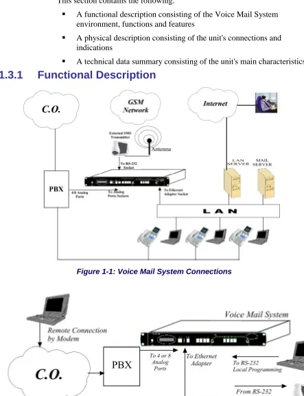
1.3.1 Functional
Description
Figure 1-1: Voice Mail System Connections
The Voice Mail System shown in Figure 1-1 and Figure 1-2 is a stand-alone
multi-lingual Automated Attendant/Voice Mail system for large to medium
sized businesses with between 50 to 300 employees.
Featuring DSP, Digital Signal Processing, flash memory storage, SMT
production and a real-time clock, the Voice Mail System contains most of
the Automated Attendant (AA), Voice Mail (VM) and administrative
features incorporated in PC-based systems.
The Voice Mail System is available in a 4 ports version with 38 hours of
memory and in an 8 ports version with 72 hours of memory. It provides up
to 500 mailboxes and integrates with most PBX systems via the analog port
or by using the SMDI protocol.
The Voice Mail System can be integrated with a Local Area Network
(LAN), using the LAN connection. This feature allows the Voice Mail
System to send a notification to the recipients. The new messages are sent
by email in the form of attached media files. They can be played on the
user’s PC. (See note.)
In addition, the mailbox owner can maintain the mailbox via the LAN, using
the Personal Mailbox Management (PMM) utility.
NOTE NOTENOTE NOTE
The Voice Mail System can be delivered with or without the email notification feature.
The media files can only be played on the user’s PC after installation of the PMM utility and the Windows Media Player.
When using the SMDI integration (Out-Band = via RS-232), the SMS Transmitter can’t be used.
As an option, an SMS transmitter can be connected to the Voice Mail
System via the RS-232 port. When new voice mail messages arrive, this
option will permit the Voice Mail System to send SMS notifications to the
mailbox owner’s cellular phone.
Figure 1-3: General View
Automated Attendant
The Automated Attendant is a menu-driven program used for transferring
calls to specific departments, extensions and mailboxes. Its main features
are:
Feature Description Opening
Greeting
The Voice Mail System plays a pre-recorded greeting to callers. The opening greeting usually includes the organization’s name and instructions on how to reach an extension, department or Operator, how to switch to different languages, how to leave a message and how to access a directory.
While the greeting is being played, the callers can access a department by dialing a single digit, dialing an extension number or holding on for assistance.
Number of Script Repetitions
The Voice Mail System plays a pre-recorded greeting, the required number of times, before executing an operation at the end of the recording.
Operating Modes
Depending on the time and system schedule, the Voice Mail System assumes one of four operating modes:
• The day mode for normal business hours. The Voice Mail System answers calls with a pre-recorded daygreeting, prompting the caller to enter a desired extension, mailbox, department or directory, or to switch to a different
language.
• The night mode for after working hours. The Voice Mail System answers calls with a pre-recorded night greeting that enables the caller to leave a message in a desired mailbox.
• The holiday mode. During holidays calls are answered with a special greeting, prompting the caller to leave a message in a specific mailbox or in the Operator’s mailbox.
• The break mode. This enables the Administrator to program a special greeting for breaks during the day.
System Schedules
Feature Description
When the auto-mode is activated, the Voice Mail System automatically switches between the day, night and break modes, according to a pre-defined schedule.
The Operator can override the pre-defined schedule and switch manually to the day, night, break, or holiday mode, using a password.
The Voice Mail System switches automatically to holiday mode on dates programmed as holidays. During holidays, the Voice Mail System answers calls with the special holiday greeting, recorded by the administrator.
Fax Detection If the Voice Mail System detects a fax tone (CNG) during the opening greeting, it automatically transfers the call to the pre-defined fax extension. There are up to four fax extensions available in the Voice Mail System.
Directory Listing (Dial By Name)
The Voice Mail System enables the caller to locate a mailbox owner. This is done by dialing the first three letters of the desired parties first or last name. The mailbox owner programs this feature.
Call Transfer The call is transferred to an extension, in a predefined mode. The modes can be:
• Non-Supervised− the Voice Mail System transfers the call immediately, without verifying the status of the extension.
• Supervised − the Voice Mail System checks for a Busy or No Answer signal, before transferring the call to the extension.
• Semi-Supervised− the Voice Mail System only checks for a Busy signal, before transferring the call to an extension. The Administrator can program the Voice Mail System to detect the Call Progress tone and DTMF signals sent by the PBX.
Multi-lingual Option
The Voice Mail System allows up to 3 languages per unit. Callers can choose the preferred language from the Automated Attendant during the opening-greeting menu. The
Administrator can select the mailbox menu language for each mailbox owner.
Answering on the First Ring
To avoid delays, the Administrator can configure each individual port of the Voice Mail System to answer incoming calls on the first ring.
Script Menus The Voice Mail System supports up to 98 script menus. A script menu is a recorded announcement that can accept a digit entry (0 to 9) while being played. Based on the digit entered, the Voice Mail System can perform one of the following actions:
• Transfer the call to another script menu
Feature Description
language
• Transfer the call to an extension or hunt group
• Transfer the call to a mailbox or a mailbox group
• Transfer the call to a specified Operator
• Dial a DTMF string
• Retrieve messages from a mailbox
• Disconnect the line
• Leave a message
• Play the directory listing
Transfer Call to Operator
Up to eight extensions can be defined as Operators and a call can be transferred from the Script Menu or from the Personal Greeting message to a specified Operator.
Dial a String The Voice Mail System can be programmed to dial any predefined DTMF string, while the script opening-greeting message is being played. “Dial a String” can perform an internal PBX feature, i.e. during the company greeting, the external subscriber is instructed to press 7, to be able to connect to another external subscriber. “Dial a String” will convert the digit 7 to hook flash, plus the external line access code, plus the subscriber number and disconnect the Voice Mail System.
Greeting by Port
The Voice Mail System can be programmed to play an Opening Greeting Message, when detecting an incoming call on a specified port.
Import *.WAV file
Windows media files (*.wav) can be used to create Script Opening Greeting Messages. A source *.wav file can be transferred and automatically converted into the required Voice Mail System format.
Voice Mail
The Voice Mail System receives and delivers messages using mailbox ID
numbers and mailbox owners' passwords. Messages can be saved, deleted or
transferred to other mailboxes. The main features are:
Feature Description Real/Virtual
Mailboxes
The Voice Mail System supports up to 500 real and virtual mailboxes. A real mailbox is associated with an extension, whereas a virtual mailbox is not.
Personalized Mailboxes
Mailbox owners can personalize their mailboxes by recording a personal greeting, assigning a personal password to the mailbox and setting optional parameters.
Message Waiting Notification
Feature Description
notification. Notification to pagers is also supported. Some features may require special hardware in order to operate.
Mailbox Features
• Personal Greeting – mailbox owners can record or change personal greetings from any touch-tone telephone at all times. First, callers hear the personal greeting of the called extension. Then they can leave a message or transfer the call to an Operator or to another extension.
• Date and Time Stamp – the Administrator can program the Voice Mail System to indicate the start of a message and the date and time each message was recorded.
• Message Deletion – messages are deleted, either manually by the mailbox owner or automatically after a maximum number of days, defined by the Administrator.
• Message Forwarding – the mailbox owners can forward copies of messages to other mailboxes or mailbox groups. Mailbox owners can also record an introduction to the forwarded message.
• Message Reply – mailbox owners can reply to messages and record messages in the sender’s mailbox.
Unified Messaging
A user can receive an email with or without a media attachment in his regular email program.
Personal Mailbox Management
A mailbox owner can maintain a mailbox via the local network, based on the TCP/IP protocol, using the Personal Mailbox Management (PMM) utility.
Mailbox Groups
A caller can send a message to all the members of a mailbox group simultaneously.
All defined mailboxes belong to the All Group mailbox group. In addition, the Administrator can create up to four mailbox groups, each containing up to twenty mailboxes. Mailboxes can belong to more than one group. Mailboxes can be added or deleted from a mailbox group by the Administrator. A mailbox group greeting can be assigned to each mailbox group.
Do Not Disturb Mode
Mailbox owners can set their mailboxes in the Do Not Disturb Mode.
When a caller dials an extension that is in the Do Not Disturb mode, via the Automated Attendant menus, the Voice Mail System plays a special Do Not Disturb menu and does not transfer the call to the extension.
Individual Language Selection
The mailbox owner can select one of the languages supported by the Voice Mail System. When the mailbox owner enters the mailbox, the Voice Mail System automatically switches to the selected language.
Adjustable Recording Length
The Administrator can select the length of all Voice Mail System recorded messages. The selected length controls the following types of messages: scripts, greetings, names and
Feature Description
received messages.
Number of Stored Messages
Each mailbox can store up to 92 messages. The Administrator controls and can change this parameter for each mailbox. The default setting for this parameter is 30. The Administrator can also limit the number of days, for which messages can be stored in the mailboxes.
System Administration
The Voice Mail System is equipped with many administrative functions.
They are intended to provide the Administrator with flexible tools for fast
implementation, setup and programming, as well as for long-term operations
like monitoring and maintenance. The main administrative features of the
Voice Mail System are:
Feature Description
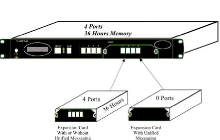
Configuration The basic Voice Mail System unit has four ports and 36 hours of recording time.
A qualified technical person can increase the number of ports and recording time, by adding a four-port expansion module to the basic Voice Mail System unit.
Programming The Administrator can program the Voice Mail System using:
• A computer running the Voice Mail Utility Program. In this case, it is highly recommended to save the
configuration files before each installation.
• Via a modem connection.
• Via a touch-tone telephone using DTMF Codes.
Integration with Your PBX
The Administrator can integrate the Voice Mail System with the PBX using:
• The in-band DTMF Protocol. This type of integration is achieved by setting up the communication protocol of the PBX and the Voice Mail System unit (answering a call, transferring a call, recalling as a result of a Busy or No Answer condition, etc.).
• The SMDI Integration via the RS-232 serial port. This type of integration must be specifically developed for each type of PBX.
Disconnection Methods
Some PBXs can notify the Voice Mail System when a call is terminated through the line interface, using Loop Disconnect, DTMF Codes or the Busy and Disconnect Cadence. When the Voice Mail System detects this situation, the line is
disconnected and the unit is ready to receive another call.
Message Notification
Feature Description
email (to a predefined email address)). The system administrator can give permission to use the external notification to mailbox’s owners.
Security Passwords
The Voice Mail System supports three types of 4-digit passwords:
• Administrator for accessing all data stored in the Voice Mail System.
• Operator for accessing the system operating modes: Day, Night, Holiday and Break.
• Mailbox for accessing individual mailboxes, where the mailbox owners can change their password at all times.
Line Monitor This option has been enhanced with the possibility to display all incoming and outgoing DTMF and system codes through the RS-232 cable or modem connection.
Modem Support
The Voice Mail System unit is equipped with a built in V.32 bis modem, operating at 14.4 Kbps with a fallback rate of 9.6 Kbps. When the call is terminated, the Voice Mail System hangs up in order to clear the port for the next call.
Modem support can be enabled or disabled.
LCD On the front panel of the Voice Mail System the LCD display
shows the status of all 4 or 8 ports, system error messages and the current mode of operation.
Reports and Configuration Print out
The Voice Mail System can provide a printout of the statistic and system configuration reports. The statistic reports contain general information about usage (memory, ports, mailboxes) and the configuration reports contain information regarding the Voice Mail System configuration.
Backup and Restore Feature
The Voice-mail Utility Program (VUP) creates a backup file via the local RS-232 connection, which includes the complete system configuration and recordings.
Software Upload
The VUP updates the system software only via the local RS-232 connection.
Extension Size
The Voice Mail System supports flexible extension sizes between 2 to 6 digits.
Memory Re-organization
The flash memory is re-organized in a manner, similar to the de-fragmentation process deployed for PCs hard disks. The Voice Mail System constantly monitors the memory usage and automatically activates the memory reorganization.
Memory Alarm
When 85% of the memory has been used, the Voice Mail System sends a voice alarm message to the "supervisor mailbox".
PBX Selection
Feature Description
Wizard An Installation Wizard has been provided in the software.
1.3.2 Physical
Description
The Voice Mail System unit is built in a 422 x 43 x 165mm metal case,
suitable for mounting in a standard 19" communication rack or on a wall.
All Voice Mail System connection and display components are located on
the unit's front panel, as shown in.
Figure 1-4: Front Panel.
For details regarding the front panel components, refer to Table 1-1
Table 1-1: Voice Mail System Connections and Display
No. ID Item Function
1
1
1
1
9VDC 1.5AConnector Connects the Voice Mail System to an external power
supply.
2
2
2
2
- 16x2 characterLCD display
Displays the operational mode and populated ports of the unit or a brief message in case of error.
3
3
3
3
Ethernet RJ-45 socket Connects the Voice Mail System to the Local Network.4
4
4
4
RS-232 RJ-11 socket Connects the Voice Mail System to a PBX or PC.5
5
5
1.3.3 Technical
Data
General Data
Number of PBX extension ports 4 or 8
Extension size 2 to 6 digits flexible
Recording time 4 ports – 36 hours
8 ports – 72 hours
Mailboxes 500
Messages per mailbox Up to 92 (programmable)
Operator's extensions Up to 8
Fax extensions Up to 4
Script messages Up to 98
DTMF strings Up to 10
In-band DTMF entries Up to 20
Legal extension groups Up to 10
Modem support
Interface V.32 bis
Rates 14.4 Kbps with fallback to 9.6 Kbps
Number of languages Up to 3
Features
Automated Attendant Opening greeting
Number of Opening Greetings repetitions
Operating modes: day, night, holiday, break
System schedules: daily, weekly, holidays
Fax detection
Directory listing (dial by name)
Call transfer modes: non-supervised, supervised, semi-supervised
Multi-lingual option
Answering on first ring
Script menus
Transfer call to specific Operator
Transfer call to extension, mailbox, group of mailboxes
Dial a string
Features
Voice Mail Real/virtual, announcer mailboxes
Personalized mailboxes
Unified messaging – email notification (This feature can be activated using special hardware.)
Message waiting notification (Local – Lamp, Ring and External – External Phone Number, Pager, SMS*)
* - The SMS feature can be activated using additional hardware.
Personal greeting
Day and time stamp
Message handling: deletion, forwarding, reply, save
Mailbox groups
Do Not Disturb mode
Adjustable recording length
Quantity of stored messages
Administration Configuration: 4 or 8 PBX extension ports
Importing *.WAV files for Script opening greetings
Programming: PC or touch-tone telephone
Integration with PBX: in-band DTMF Protocol or out-of-band via RS-232 port
Disconnection methods: Loop Disconnect, DTMF Disconnect, Busy Disconnect and Disconnect tones
Security passwords: Administrator, Operator, mailbox
Line monitor: incoming/outgoing calls via RS-232 port or modem connection
Modem support: enabled/disabled
LCD: front panel monitoring
Reports: statistics and configuration print-out
Backup and restore: system configuration and recordings
Software download: via RS-232 port
Memory re-organization
Memory Alarm: when 85% in use
Define mailbox owner’s permission for external notification and unified messaging
Characteristics Electrical
DC Power Supply 9VDC/1.5 A
Line Voltage 24 to 72VDC
DC Leakage Current 10µA maximum
On-hook Insulation Resistance between Line Terminal and Ground
0 to 100VDC, 5MΩ minimum
100 to 200VDC, 30KΩ minimum
500 VAC/50Hz, 20KΩ minimum
100 VAC/25Hz, 100KΩ minimum
Ring Capacitor 0.47µF ± 10%
On-hook Impedance @ 50VDC, 40 VAC/25Hz, 3000Ω minimum
Ring Detect 27 to 100VAC/16 to 60Hz
DC Resistance (off-hook) 24 to 66VDC @ 20 to 100mA, 100 to 350Ω
Impedance (off-hook) 300 to 3400Hz, 500 to 700Ω
Imbalance Ratio 300 to 3400Hz, 46dB minimum
Return Loss 300 to 3400Hz, > 18dB
Current during Break 700µA, maximum
DTMF Transmission:
Frequency Tolerance
Frequency Level (High Group)
Frequency Level (Low Group)
+1.5% -6 to -8dBm -8 to –10dBm
Inter-digit Pause in Tone Dialing
70 to 80ms
Fax CNG Tone Detection 1100Hz ± 38Hz
Mechanical
Dimensions (W x H x D) 422 x 43 x 165 mm
Weight 2.2 Kg
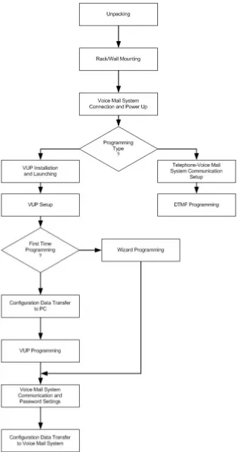
1.4 Workflow
2
Installation
This chapter contains the following:
Unpacking the Voice Mail System unit and accessories
Installation of the Voice Mail System
Installing and setup of the VUP software
2.1 Unpacking
Check if the Voice Mail System package complies with the packing list in
Table 2-1.
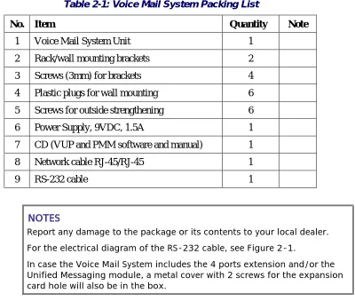
Table 2-1: Voice Mail System Packing List
No. Item Quantity Note
1 Voice Mail System Unit 1
2 Rack/wall mounting brackets 2
3 Screws (3mm) for brackets 4
4 Plastic plugs for wall mounting 6
5 Screws for outside strengthening 6
6 Power Supply, 9VDC, 1.5A 1
7 CD (VUP and PMM software and manual) 1
8 Network cable RJ-45/RJ-45 1
9 RS-232 cable 1
NOTESNOTESNOTESNOTES
Report any damage to the package or its contents to your local dealer. For the electrical diagram of the RS-232 cable, see Figure 2-1.
Figure 2-1: RS-232 Cable Electrical Diagram
RJ-11 RJ-11 (Analog port input) (Analog extension socket)
Figure 2-2: Analog Ports Input Cable
2.2 Hardware Installation
This section contains the following:
Voice Mail System installation
Connections, starting up and initial indications
Voice Mail System expansion to eight ports
NOTENOTE NOTENOTEVUP programming can be done prior to the hardware installation (see VUP2.2.1
Voice Mail System Installation
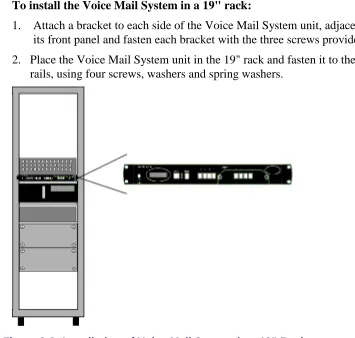
To install the Voice Mail System in a 19" rack:
1. Attach a bracket to each side of the Voice Mail System unit, adjacent to
its front panel and fasten each bracket with the three screws provided.
2. Place the Voice Mail System unit in the 19" rack and fasten it to the rack
rails, using four screws, washers and spring washers.
Figure 2-3: Installation of Voice Mail System in a 19” Rack
To install the Voice Mail System on a wall:
1. Attach a bracket to each side of the Voice Mail System unit, adjacent to
its top panel (see Figure 2-2:) and fasten each bracket with the two
screws provided.
2. Drill four holes in the wall.
3. Fasten the Voice Mail System unit to the wall using four screws,
washers and spring washers provided.
2.2.2
Connections, Starting Up and Initial Indications
1. Connect each port (4 or 8) to an extension line, using an RJ-11 cable.
The ports can be found on the right side of the front panel of the Voice
Mail System unit.
NOTENOTE NOTENOTEEach RJ-11 socket on the front panel of the Voice Mail System supports one analog telephone line.Make sure that the Analog Ports Input Cables are according to the specifications in Figure 2-2:.Figure 2-2:Figure 2-2:
CAUTIONCAUTIONCAUTIONCAUTION In order to prevent damage to the RS-232 driver chip, DO NOT connect an
analog telephone line to the RS-232 socket.
2. Plug the RJ-45 Network cable into the “Ethernet” socket of the Voice
Mail System front panel.
3. Plug the 9V DC adapter jack into the power supply connector on the left
side of Voice Mail System front panel.
4. Plug the 9V DC adapter into the main power supply outlet, to turn the
Voice Mail System on.
5. Notice the indications on the LCD display. For details, see
LCD
Messages
in Chapter 4.
6. For local programming of the Voice Mail System, connect the RS-232
cable between the Voice Mail Systems RS-232 socket and the COM port
of the PC running the VUP program.
7. Plug the external SMS transmitter into the RS-232 socket. (The external
SMS transmitter can’t be connected simultaneously with the local
programming PC. Details for using the
SMS transmitter
can be found in
Chapter 8).
Remote programming of the Voice Mail System can be done via a
modem connected to the public network. The Administrator has to
enable this option in the Voice Mail System.
NOTESNOTES Voice Mail System connections for local and remote programming, are NOTESNOTESschematically shown in Figure 1-1 and Figure 1-2.
For local programming, an RS-232 cable is included in the Voice Mail System package.
8. Call each Voice Mail System line from any extension and listen to the
default greeting, informing you that the system has not been
programmed yet (see
VM System Messages
, System Message No. 000).
2.2.3 Physical
Expansion
The Voice Mail System can be configured in one of the following
combinations:
4 or 8 analog ports
4 analog ports with unified messaging features
8 analog ports without unified messaging features
8 analog ports with unified messaging features
For a physical upgrade of the Voice Mail System, one of the following 3
expansion modules:
Unified messaging expansion module
4 ports, 32 hours of memory expansion module
4 ports, 32 hours of memory and Unified Messaging expansion module
Upgrading a Voice Mail System unit
1. Make sure that the Voice Mail System is not connected to the power
supply.
2. Remove the two screws and the cover from the expansion slot on the
right side of the front panel. (See Figure 2-5).
3. Slide the expansion card into the slot and carefully push it in until it fits
into the unit's rear connector.
4. Fasten the expansion card, using its two captive screws to the unit's front
panel.
5. Plug in the power supply.
Figure 2-5: Expanding the Voice Mail System
2.3 Software Setup
This section contains the following:
Installing the VUP software
Selecting a PBX
Configuring the VUP toolbars
2.3.1
Installing the VUP Software
Install the VUP software on the Administrator’s PC or laptop. This PC or
laptop is being used for the setup, programming and managing of the Voice
Mail System unit.
NOTESNOTES NOTESNOTES
The VUP software can be installed and used for creating the Voice Mail System configuration and programming Scripts, without physically connecting the PC to the Voice Mail System unit.
The following may happen when the PC containing the VUP software is physically connected to the Voice Mail System unit. A message, indicating that the COM port of the PC has not been configured, may appear, when performing a software download. Press OKOKOKOK and configure the COM port. To establish a connection, follow the relevant procedures: Connections, Powering Up and Initial Indications in Chapter 2 and Setting the VUP PC – Voice Mail System Communication in Chapter 4.
To install the VUP software
1. Insert the VUP CD in the CD-ROM drive of your PC.
2. The CD should run automatically. If it doesn’t, press
Start
Run
and
browse the CD for the
VUP Set up
icon.
3. Click on the
VUP Installation
icon and follow the instructions on the
screen.
4. To start the VUP program, click
Start
Programs
Voice Mail
System
. The VUP main screen appears (see Figure 2-6).
Figure 2-6: VUP Main Screen
2.3.2 PBX
Selection
Selecting a PBX from the PBX Selection list enables a quick and easy
integration of the Voice Mail System. All the default parameters for the
selected PBX will automatically be shown in the VUP. These parameters
are: Transfer Code, Hook Flash Time, Message Light On and Off codes and
In-band DTMF Protocol. Refer to
PBX Settings
in order to change the
parameters not provided in the PBX selection.
To select a PBX
1. Press
the
PBX Selection
button in the VUP toolbar.
2. From
the
PBX Selection
dialog (see Figure 2-7), select the relevant
PBX and press
OK
.
Figure 2-7: PBX Selection List
Parameters applied when selecting a PBX, may differ from the parameters of CAUTIONCAUTIONCAUTIONCAUTION
the existing PBX. In this case, request for assistance from the PBX manufacturer.
To obtain a list of the PBX parameters from the VUP main menu, select File File File File
Print Settings Menu Print Settings Menu Print Settings Menu Print Settings Menu PBX Parameters PBX Parameters PBX Parameters PBX Parameters.
2.3.3
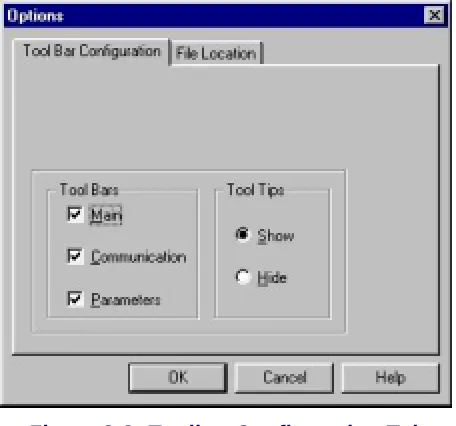
Configuring the VUP Toolbars
This function is used for selecting which toolbars and whether tooltips will
be displayed.
To configure the VUP toolbars
Figure 2-8: Toolbar Configuration Tab
2. In
the
Tool Bar
section, check the boxes of the required toolbars.
3. In
the
Tool Tips
section, click
Hide
to only show the tool name when
moving the cursor over it.
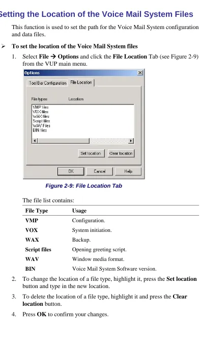
2.3.4
Setting the Location of the Voice Mail System Files
This function is used to set the path for the Voice Mail System configuration
and data files.
To set the location of the Voice Mail System files
1. Select
File
Options
and click the
File Location
Tab (see Figure 2-9)
from the VUP main menu.
Figure 2-9: File Location Tab
The file list contains:
File Type Usage
VMP Configuration.
VOX System initiation.
WAX Backup.
Script files Opening greeting script.
WAV Window media format.
BIN Voice Mail System Software version.
2. To change the location of a file type, highlight it, press the
Set location
button and type in the new location.
3. To delete the location of a file type, highlight it and press the
Clear
location
button.
3
VUP Programming
This chapter contains the following:
Quick Voice Mail System Installation using the Installation Wizard
Programming the Voice Mail System’s system parameters
Programming the Voice Mail System's Automated Attendant (AA)
Programming the Voice Mail System's Voice Mail (VM)
To program the Voice Mail System unit using a touch-tone telephone, see
Chapter 6,
DTMF Programming
.
3.1 Quick Installation Using the Installation Wizard
The Voice Mail System Installation Wizard is especially recommended as
the initial fast, hands-on installation tool.
To use the Voice Mail System Installation Wizard
1. Select
Wizard
Start
from the menu bar.
Alternatively, click on the Installation Wizard icon
on the toolbar.
2. After opening the
Wizard
, press
start
. The first out of the following ten
dialogs will appear.
3. In these dialogs, enter the following parameters:
No. Dialog Description Reference
1 PBX
Parameters
Operator Extensions, Fax Extensions, PBX Legal Extensions
Figure 3-1
2 PBX
Parameters
Transfer mode Figure 3-2
3 PBX
Parameters
Busy Tone, Disconnect Tone Figure 3-3
4 List of Mailboxes
Range of mailboxes Figure 3-15
(similar)
5 Notification Parameters
PBX code used to turn the message light on and off
Figure 3-18 (similar)
6 In-band DTMF Protocol
Codes from a PBX that supports the In-band DTMF Protocol to the Voice Mail extension
No. Dialog Description Reference
7 In-band DTMF Protocol
Page 2 for additional 10 events -
8 Script Menu The operation associated with each script
Figure 3-8
9 Network Parameters
Relevant Network settings for the Voice Mail System
10 Final Wizard Script
Finish to save your settings or Cancel
to return to the Voice Mail System opening screen without saving the Wizard settings
3.2 System Programming
To program the Voice Mail System’s system parameters, the following
procedures apply:
Setting the PBX parameters
Setting the system parameters
Setting the In-band DTMF Protocol parameters
Setting the Network Parameters
3.2.1
Setting the PBX Parameters
NOTENOTE NOTENOTE
For programming the PBX parameters of the Voice Mail System unit using a touch-tone telephone, see Table 5-2 in Chapter 5.
To set the PBX parameters
1. Select
Parameters
PBX Parameters
from the menu bar. The PBX
Parameters dialog appears (see Figure 3-1).
Figure 3-1: PBX Parameters Dialog
2. In
the
Extensions
tab, enter the numbers and ranges of the PBX
extension types (enter two to six digits in the extension number fields of
Figure 3-1):
Extension Type Usage
Operator Defines eight Operator extensions for script and mailbox programming.
PBX Legal Extension
Defines 10 extension ranges for Direct Call to Extension. Extensions outside these ranges can’t be directly accessed via the Automated Attendant scripts.
Fax Defines four extensions for “call transfer”, on detection
of the fax tone by the Voice Mail System. Leaving these fields empty disables the feature.
Figure 3-2: Call Transfer Tab
Parameter Usage Transfer
Supervise Type
Defines the method for detecting the No Answer, Busy and Do Not Disturb (DND) status when a call is transferred to an extension in semi-supervised or supervised mode. Select:
Type Details Call Progress Tones The Voice Mail System
samples the sounds from the PBX (Busy tone, Disconnect tone, etc.).
DTMF The Voice Mail System receives the DTMF signals for Busy, No Answer and DND from the PBX.
DTMF Codes from PBX
Defines the "answer", Busy and DND signals after switching to DTMF in the Transfer Supervise Type
drop-down menu.
Transfer Mode Defines the transfer mode of the Operator and other extensions. Select:
Mode To Non-supervised Transfer the call without
Parameter Usage
Semi-supervised Check for a Busy signal on the required extension.
Supervised Check for a Busy or No Answer signal on the required extension.
Transfer Code Transfers a call from the Script or Personal greeting to another telephone number. The applicable codes are:
Code To indicate
& Hook flash.
X Extension.
0-9, A-D DTMF.
P Pause.
Recall from Busy Code
Defines the PBX code to return the caller to the Voice Mail System when the required party is busy (this code is applicable for semi-supervised or supervised mode only).
Recall from No-answer Code
Defines the PBX code to return the caller to the Voice Mail System when his/her call is not answered (this code is applicable for supervised mode only).
Recall from Hold on busy retry Code
Defines the PBX code to return the call placed on Hold during the “Busy menu” playback to the Voice Mail System.
Hook Flash Time (&)
Defines the hook flash time in milliseconds.
Time to Wait for No Answer
Defines the Voice Mail System waiting period for an answer after transferring a call in supervised mode (the default is 20 seconds).
Voice Sensitivity
Defines the sensitivity to human voice in supervised mode. (Default is 5.)
Menu Activator
Works only in Supervisor mode. Otherwise it will playback the personal greeting.
Menu Details No Answer menu When a call is transferred from
an extension with no answer to the Voice Mail System, the caller will hear a No Answer menu.
Busy menu When a call is transferred from a busy extension to the Voice Mail System, the caller will hear a Busy menu.
Parameter Usage
Disturb to the Voice Mail System, the caller will hear the DND menu.
4. In
the
CP Tone & Disconnect
tab, the on-time and off-time of the
following tones are set (see Figure 3-3):
Figure 3-3: CP Tone & Disconnect Tab
Tone Usage
Busy, External Busy Detects a busy extension when a call is
transferred in semi-supervised or supervised mode and disconnects the line when a Disconnect situation is detected.
Disconnect,
External Disconnect
Disconnects the line when the caller hangs up and the disconnect tones are detected.
5. Enter
the
Disconnect Code.
Defines the DTMF codes sent from the
PBX to the Voice Mail System, in order to disconnect the line, when a
caller has hung up.
3.2.2 System
Parameters
NOTENOTE NOTENOTE
For programming the system parameters of the Voice Mail System unit using a touch-tone telephone, see Table 5-3 and Table 5-6 in Chapter 5.
1. Select
Parameters
System Parameters
from the menu bar. The
Parameters
tab appears (see Figure 3-4).
Figure 3-4: System Parameters Tab
2. Select
the
Default System Language
by clicking on the appropriate
radio button
.
NOTESNOTES NOTESNOTES
The list of installed languages will only be shown after a Read Parameters operation.
Use the Statistics window (see Using Statistics in Chapter 4) after a “Read Parameters” operation, to check the number of the languages installed in the system. For a new system, the number of installed languages is also specified on the package.
3. Select
Last
or
First Name
to be used as selection, when using the
Directory Listing feature.
4. Press
the
Advanced
button to change parameters, which affect the unit's
operation as indicated by an appropriate warning message.
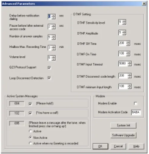
Figure 3-5: Advanced Parameters Dialog
6. Modify and mark the parameters in the advanced Parameters dialogue.
Define system parameters as follows:
Parameter Usage Delay before
notification dialing
Defines the time delay in seconds, before a dialing notification string is sent.
Pause before/after external access code
Defines the time delay before/after dialing an external code.
Number of answer samples
Defines how fast the Voice Mail System in Supervisor mode will recognize a human voice from a called extension.
Maximum recording time
Defines the maximum recording time for user messages, mailbox greetings and names.
Volume level Defines the volume level of a message played via an analog port.
Check boxes as necessary:
Check To enable
Q23 protocol support A special protocol, when integrating the Voice Mail System with the MATRA PBX.
In the
DTMF Setting
section, the dual arrow buttons can be used to
enter the relevant DTMF parameters.
Parameter Usage
DTMF Sensitivity Level Defines the sensitivity for DTMF codes dialed by the PBX.
DTMF Amplitude Defines the outgoing DTMF tone level.
DTMF Off Time Defines the DTMF OFF time length.
DTMF On Time Defines the DTMF ON time length.
DTMF Input Timeout Defines the maximum time between DTMF signals, in which the caller has to enter the relevant data.
DTMF Disconnect Code Length
Defines the length of the DTMF cadence cycle, sent by the PBX, when a call is disconnected. This parameter is needed in order to calculate the amount of time that must be truncated from the end of a message, which was terminated by a Disconnect Code.
DTMF Minimum Input Length
Defines the length of the DTMF ON tone, used by the PBX. This parameter helps to differentiate between voice and actual DTMFs.
To enable
Active System Messages
, check boxes as follows:
Check To enable
Please hold System message 004 playback before transferring a call.
You have a call System message 102 playback after the target extension answered.
Please leave a message after the tone
System message 095. Additional options after leaving a message.
To enable
the modem
, check boxes as follows:
Check To enable
Modem Enable Modem, connecting from a remote PC
Modem Activation Code Activation code for the built-in Voice Mail System modem. (Valid codes are 0-9, A, B, C, D and #.) (* can’t be used!)
CAUTIONCAUTIONCAUTIONCAUTION Please notice that following the system initialization, all previously
recorded messages are deleted.
For a system initialization, a special *.vox file must be used, prepared by the manufacturer. Using the incorrect *.vox file can destroy a Voice Mail System.
8. To upgrade the Voice Mail System system software, press the
Software
Upgrade
button. Use the
Browse
option to define the path of the *.bin
file. For more details regarding this option, refer to
Software Upgrade
in
Chapter 5.
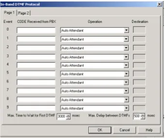
3.2.3
In-band DTMF Protocol
The In-band DTMF Protocol is used for defining DTMF strings, sent from
the PBX to the Voice Mail System unit. The Voice Mail System extension
needs to be defined as a VM extension.
Each string is associated with an operation that is executed once the Voice
Mail System receives a DTMF string. A string contains up to 20 digits: 0 to
9, A to D, #, and *.
NOTENOTE NOTENOTE
For programming the In-band DTMF Protocol of the Voice Mail System unit using a touch-tone telephone, see Table 5-4 in Chapter 5.
To define DTMF strings, using the in-band DTMF protocol
1. Select
Parameters
In-band DTMF Protocol
from the menu bar.
The
In-band DTMF Protocol
dialog appears (see Figure 3-6).
NOTENOTE NOTENOTE
Figure 3-6: In-band DTMF Protocol Dialog
2. Enter
the
Code Received from the PBX
and select the required
Operation
from the operation drop-down menu on the right.
Select To Auto Attendant Play the opening script of the
Automated Attendant.
Transfer to a Script Message Play a specific script.
Transfer to a script Message + 1st/2nd/3rd Language
Play a specific script and change to the specified language (1, 2 or 3).
Transfer to Busy Menu Play the Busy menu.
Transfer to No Answer Menu Play the No Answer menu.
Transfer to Do Not Disturb Menu Play the Do Not Disturb menu.
Transfer to an Extension Transfer a call to a required extension.
Transfer to a Mailbox Transfer a call to a required mailbox.
Transfer to the Operator Transfer a call to a required operator, 1 out of 8.
Directory List Play the Directory Listing (DBN)
Select To
supported.)
Leave a Message Leave a message in a designated mailbox.
Retrieve Messages Retrieve messages from a designated mailbox.
Disconnect Disconnect the call.
Transfer to a Group of Mailboxes Leave a message for a group of
mailboxes.
3. Set the maximum time interval that the Voice Mail System has to wait
in mili seconds, until the first DTMF string is received.
4. Set the maximum time delay between DTMF codes sent from the PBX
to the Voice Mail System.
NOTENOTE NOTENOTE
The main opening greeting is played, if a DTMF is not received within the allocated time, defined in the two parameters above.
5. Press
the
OK
button to confirm your settings and return to the VUP
main screen.
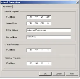
3.2.4 Network
Parameters
NNNOTENOTEOTEOTE
Network Parameters will only be activated after the Send Parameters operation and physical hardware system reset have been performed. To define large-scale network parameters, you may need a Local Network Administrator’s assistance.
The Local Network Administrator needs to define a user for the Voice Mail System on the Exchange Server.
To enable network features, the Voice Mail System needs to be integrated
into the TCP/IP protocol based Local Area Network. Enter the Voice Mail
System to the LAN, as a regular Network user. This is possible via the
definition of the Network Parameters.
To activate the possibility to send emails from the Voice Mail System to
mailbox owners, the IP address of the SMTP server needs to be defined. A
mailbox for the Voice Mail System needs to be defined on the Local Area
Network. For this the help of the Local Network Administrator is needed.
To set the Network Parameters
1. Select
Parameters
Network Parameters
from the menu bar. The
Figure 3-7: Network Parameters
Parameter Usage
IP Address Defines the permanent Voice Mail System IP Address, which has to be unique in the existing LAN. (It is recommended to us the permanent IP address and not a DHCP address.)
Subnet Mask Defines the Subnet Mask stamp for the existing LAN.
Email Address Defines the email address from the Voice Mail System, as defined in the LAN. This address is needed when the Unified Messaging feature is activated.
Display Name Defines the name of the Voice Mail System, as originator from an email message, sent to the mailbox of a user. (Only when the Unified Messaging feature is activated.)
“Server Properties” – IP Address
Local SMTP Server IP Address.
“Gateway Properties” – IP address
IP Address of the Network Communication device (Router, Firewall, etc.), which
3.3 Automated Attendant Programming
The following steps apply to the programming of the Voice Mail System
Automated Attendant:
Script programming
Schedule programming
3.3.1
Script Programming
Define the operation executed when pressing any DTMF digit between
0 and 9, while the script message is being played, etc.
Define the script opening conditions per port and the number of the
script to be played for each port.
Define a name for each necessary operational script, i.e. company
greeting in English, script 00 and company greeting in Spanish, script
01, etc.
Display of script listings for reviewing the script status.
NOTESNOTES NOTESNOTES
For programming the AA script of the Voice Mail System unit, using a touch-tone telephone, see Table 5-5 in Chapter 5.
Please note that a script must be recorded and programmed with an announcement, in order for a script to operate.
To program scripts
1. Select
AutoAttendant
Script Menu
from the menu bar. The
Script
Menu
appears (see Figure 3-8).
2. To define an operation for each DTMF digit (0 to 9), select the
respective
Type of Operation
from the drop-down menu. The
operations to choose from are as follows:
Operation When pressing appropriate DTMF digit Transfer to a script menu The caller is transferred to the sub-menu,
defined in the respective Destination field.
Transfer to a Script Message + 1st Language, Transfer to a Script Message + 2nd Language, Transfer to a Script Message + 3rd Language
The caller is transferred to the sub-menu, defined in the respective Destination field and the selected language is used until the end of the session.
Directory List The Voice Mail System requires the caller to enter the first three letters of the first or last name of the desired party (for details regarding the dial by name option, see
System Parameters).
Transfer to an Extension The call is transferred to the predefined extension, as defined in the relevant
Destination field. (Up to six digits irrespective of the legal number of the extension.)
Transfer to a Mailbox The caller is immediately allowed to dial the required mailbox, defined in the relevant
Destination field.
Transfer to a Group of Mailboxes
Leave a message for a group of mailboxes.
Direct Call to an Extension
The caller is allowed to dial the required extension, which is a legal PBX extension, defined independently (see PBX Settings).
Direct Call to a Mailbox The caller is allowed to dial the required mailbox, which is a legal extension.
Leave a Message The caller is allowed to press a predefined digit from 0 to 9, and is then prompted to enter the requested mailbox number, for leaving a message.
Retrieve Messages The caller is allowed to press a predefined digit from 0 to 9 and is then prompted to enter the required mailbox number and personal password, in order to retrieve messages.
Disconnect The caller is disconnected.
Operation When pressing appropriate DTMF digit Dial-a-String Enter a string number from the dial-a-string
table for special PBX applications (see the
Dial Strings tab below in this section).
Transfer to Operator A caller can be transferred from a script message to an Operator, as defined in the
PBX Settings.
Import WAV A *.wav file can be imported and can be transferred to a specified script, such as a greeting message.
3. To define a number of times the Script Opening Greeting playback is
played, set the
Repeat
script parameter.
4
To define the time interval after the Script Opening Greeting, in which
the caller needs to respond, set the
EOM Timeout
in seconds.
5. Define in each script 1 fax extension out of 4, to which a fax call will be
directed. Please note that each script menu can have a different fax
extension.
6. To define a source *.wav file for a specified script, such as the opening
greeting message, press the
Import WAV
button.
NOTENOTE NOTENOTE
The *.wav source file parameters are: 8kHz, 16-bit, mono.
To define the script opening conditions
Figure 3-9: Script Opening Tab
2. Set for each line in use, the
Number of Rings
before a call is answered.
3. Set the script number played on each line. There can be up to four
scripts - a script for each mode of operation, i.e.
Day
,
Night
,
Break
or
Holiday
.
To review the status of the scripts
Figure 3-10: Script Status Tab
2. Press
the
Description
button to enter script details (for example, the
script file name for future reference).
To define dial strings
Figure 3-11: Dial Strings Tab
2. Define up to 10 dial strings.
NOTENOTE NOTENOTE
A dial string consists of up to 20 digits including 0 to 9, A to D, *, #, p for pause and & for hook flash.
To end the Script Menu session
Press
OK
to save your settings or press
Cancel
to return to the Voice-mail
Utility Program's (VUP) main screen, without saving any data.
3.3.2 Schedule
Programming
Schedule programming describes the following:
Defining the system time and scheduling modes
Defining weekly schedules
Defining holiday schedules
NOTENOTE NOTENOTE
For programming the AA scheduling script of the Voice Mail System unit using a touch-tone telephone, see Table 5-6 in Chapter 5.
1. Select
AutoAttendant
Time & Date
from the menu bar.
Time,
Date and Weekly Schedules
appear (see Figure 3-12).
Alternatively, click on the
Time & Date
icon
on the toolbar.
Figure 3-12: Time and Date Dialog
2. In
the
Time & Date
tab, change the daylight saving clock by using the
Auto Day Light saving time
drop-down list as follows:
Select To change the day light clock
American Automatically on the 1st Sunday of April and the last Sunday of October.
European Automatically on the last Sunday of March and the last Sunday of October.
None Manually, using a touch-tone telephone and DTMF programming.
NOTENOTE NOTENOTE
The time is automatically changed at 2:00 a.m. when selecting the American
American American
American or EuropeanEuropeanEuropeanEuropean option.
3. To set the system time and date, use the appropriate fields in this tab.
NOTENOTE NOTENOTE
The default System Time System Time System Time System Time and System DateSystem DateSystem DateSystem Date are automatically received from the PC, running the VUP software.
Select To
Auto Set the automatic scheduling mode.
Day, Night, Break, Holiday
Manually set the appropriate scheduling mode.
To define the weekly schedule
1. In
the
Time & Date
tab, select the
Auto
option from the
Mode of
Operation
pop-down menu and press the
Schedules
button. The
Auto
(automatic scheduling) dialog appears (see Figure 3-13).
Figure 3-13: Automatic Scheduling Dialog
NOTENOTE NOTENOTE
Please notice that the Schedules Schedules Schedules Schedules button is only enabled, when selecting the Auto
Auto Auto
Auto option from the Mode of OperationMode of OperationMode of Operation drop-down menu. Mode of Operation Break
Break Break
Break, NightNightNightNight and HolidayHolidayHolidayHoliday scripts have to be recorded by the Administrator. Otherwise the Voice Mail System will automatically return to the Day TimeDay TimeDay Time Day Time manual mo
manual mo manual mo manual mode.de.de.de.
2. In
the
Weekly Schedule
tab, set the
Day Time
schedule
and
Break
Time
schedule.
To define the holiday schedules
1. Click on the
Holiday Schedules
tab. The current list of holiday dates
appears (see Figure 3-14).
Figure 3-14: Holiday Schedules Tab
2. Press
the
Add
button to add a new date to the list of holidays and set the
time the holiday script message should be played.
NOTENOTE NOTENOTE
If the holiday lasts more than one day, each day must be separately added to the list.
3. To remove a holiday date from the list, highlight it and press the
Remove
button.
To end your time and date scheduling session
3.4 Programming the Voice Mail
Voice Mail programming contains the following:
List of mailboxes
Setting the message waiting notification
Defining mailbox groups
3.4.1
Handling the List of Mailboxes
The tasks associated with the list of mailboxes are:
Creating a range of mailboxes and defining a Supervisor Mailbox
Editing the list of mailboxes
Setting the parameters of the mailbox list
NOTENOTE NOTENOTE
To program the list of mailboxes of the Voice Mail System, using DTMF programming, refer to Table 5-7 in Chapter 5.
To create a range of mailboxes and define a Supervisor Mailbox
1. Select
Voice Mail
List of Mailboxes
from the menu bar. The
List of
Mailboxes
dialog appears (see Figure 3-15).
Figure 3-15: List of Mailboxes
2. To define a
Supervisor Mailbox
, select the correct mailbox from the
drop-down menu.
NOTENOTE NOTENOTE
The Supervisor Mailbox can only be defined after a number of mailboxes have been created, as one of them will have to be assigned as the
Supervisor Mailbox.
The Supervisor Mailbox is used when the Voice Mail System memory is 85% full. The System Administrator is alerted to delete messages and reorganize the system memory.
3. To create a range of mailboxes, fill in the following:
Field With
From The first mailbox in the sequence.
To The last mailbox in the sequence.
Source The mailbox with specific parameters, e.g. language or operator, etc., which is the source for the new mailbox parameters.
4. When finished, press the
Create Range
button.
To edit the list of mailboxes
1. Use the right-hand buttons as follows:
Press To
New Create a new mailbox (see Figure 3-16).
Copy Create a new mailbox based on the parameters of a highlighted mailbox.
Delete Delete the highlighted mailbox.
Edit Edit the parameters of the highlighted mailbox (see Figure 3-16).
2. To add a new mailbox, press the
New
button and the following screen
appears (see Figure 3-16).
Figure 3-16: New Mailbox
Parameter To define Note Mailbox The number of the mailbox in the list of
mailboxes.
Extension The number of the extension associated with the mailbox.
Mailbox Type The type o