78:3 (2016) 225–230 | www.jurnalteknologi.utm.my | eISSN 2180–3722 |
Jurnal
Teknologi
Full Paper
O
PTICAL
B
ISTABILITY
C
ONTROLLED
U
SING
A
DD
-
DROP
M
OBIUS
M
ICRORING
R
ESONATOR
S
YSTEM
Ahmad Fakhrurrazi Ahmad Noorden
a, Suzairi Daud
a,b*, Syed Zuhaib
Haider Rizvi
a, Jalil Ali
a,b, Preecha P. Yupapin
ca
Laser Center, Ibnu Sina Institute for Scientific & Industrial Research,
Universiti Teknologi Malaysia, 81310 UTM Johor Bahru, Johor,
Malaysia
b
Department of Physics, Faculty of Science, Universiti Teknologi
Malaysia, 81310 UTM Johor Bahru, Johor, Malaysia
c
Advanced Studies Center, Faculty of Science, King Mongkut’s
Institute of Technology Ladkrabang, Bangkok 10520, Thailand
Article history
Received 15 August 2015 Received in revised form 15 November 2015 Accepted 30 December 2015
*Corresponding author
[email protected]
Graphical abstract
AbstractThe theoretical investigation has been performed on the implementation of optical Mobius shape in add-drop microring resonator. The modified add-drop Mobius configuration is used to investigate the optical bistability and the spectral transmission. The optical bright soliton pulse is used as the input source of the resonator system. The pulses propagation of the resonator system is modelled using the iterative programming based on the transfer matrix analysis equations. The enhancement of nonlinear effect of the resonator system is achieved by the add-drop Mobius resonator configuration. The system has been modelled for a variation of coupling coefficient for increase the bistable signal properties. The Add-drop Mobius MRR generated a bistable signal with 6.01 mW hysteresis width, and 9.47 mW output switch power with optimized radius of 5 µm outer and 4.5 m inner ring parts with 50 mW controlled power and input power. Mobius configuration is found as the better shape of resonator cavity that capable of optical switching application.
Keywords: Mobius ring resonator, hysteresis loop, transfer matrix, optical bistability
Abstrak
Penyelidikan secara teori telah dilakukan mengenai pelaksanaan bentuk mobius optik penambah-lepasan cecincin mikro. Sistem penambah-lepasan mobius yang diubahsuai konfigurasinya digunakan untuk menyiasat kestabilan optik dan penghantaran spektrum. Nadi optik soliton terang digunakan sebagai sumber input sistem resonator. Denyutan penyebaran sistem resonator dimodelkan menggunakan pengaturcaraan lelaran berdasarkan persamaan analisis matriks pemindahan. Peningkatan kesan tak linear sistem resonator dicapai dengan penambah-lepasan mobius konfigurasi resonator. Sistem ini telah dimodelkan bagi pengubahan pekali gandingan untuk meningkatkan sifat-sifat isyarat kestabilan. Sistem penambah-lepasan mobius MRR menjana isyarat dwistabil dengan 6.01 mW histerisis lebar dan 9.47 mW suis output kuasa dengan radius dioptimumkan 5 mikron luar dan 4.5 m bahagian dalam cecincin dengan 50 mW kuasa dikawal dan kuasa input. Konfigurasi mobius diperoleh sebagai bentuk yang lebih baik daripada resonator rongga yang boleh terpakai pensuisan optik.
Kata kunci: Mobius cincin resonator, gelung histerisis, pemindahan matriks, dwistabil optik
1.0 INTRODUCTION
The optical switching technology is a crucial factor for providing the flexibility in a optical network connectivity. In order to provide optical switching, nonlinear respond is one of the potential technique which can produce a hysteresis pattern in input to output (I/O) power relation. This hysteresis pattern are known as optical bistability in which explain the two output power can be obtained in a range of input power [1]. The nonlinear system produced the absorptive and dispersive properties towards propagated pulse that contribute to the generation of optical bistability [2]. There are several methods have been applied for producing the optical bistability based on different type of nonlinear medium. Those method are known as crystal nanocavity [3], Fabry-perot interferometer [4, 5], fiber Bragg grating [6, 7] and optical microring resonator [8].
The optical bistability are needed to be controlled for particular application. Several reports shows the investigation on controlling the hysteresis pattern of I/O relation [9, 10]. Microring resonator (MRR) is found as an attractive nonlinear medium which contributes due to its contributions in various application as optical filter [11], lasing [12], biosensing [13, 14], optical memory [15] and optical switching [16, 17].The MRR system is able to provide several type of optical nonlinear response characteristic such as optical bifurcation [18], chaotic [19] and bistability [17, 20]. The generated optical bistability from MRR system made it breached as an attractive field of research with applications in all-optical regeneration [8], flip-flop operation [21], memory storage [15], and logic gate [22]. The design of MRR system is one of the crucial factor for improving the nonlinearity which can enhance the bistable signal [23]. In 2008, the PANDA configuration of MRR system has been introduced which comprise of one centre ring and two smaller sides ring. This configuration is used for generating optical bistability for switching application [17]. Despite of increasing the nonlinearity, the additional ring causes extra radiation loss of pulse propagation due to circular propagation trails in smaller radius as reported in [24].
There is a different approach which has been provided to overcome this problem. The design of MRR configuration is a key parameter for enhancing nonlinear response. A Mobius based design of resonator medium has been implemented to provide a compact design with higher performance.[25]. The Mobius ring has been introduced as a resonator medium of electronic devices for a number of applications such as band-pass filter [26], optical waveguide resonator [27] and also as inductive and capacitive element based on electronic-wired resonator [28]. Nevertheless, to the best of our information there is no scientific reports on the study of
optical bistability controlled using add-drop Mobius MRR configuration in theoretical or experimental work. Thus, it is a necessity to study the dynamics behavior of bistable signal for controlling its properties using Mobius MRR system.
This work provides the analytical computation of optical transfer function based on the coupled mode theory and transfer matrix analysis of the Add-drop and Add-drop Mobius MRR configurations. The input-output power relations of both configuration are analyzed for investigating the properties of the optical bistability hysteresis loop. The dispersive effect of propagating pulse is treated as a key parameter of the optical bistability generation. The properties of the hysteresis loop such as input thresholds power, hysteresis width and output switch of both MRR configurations are compared. The dynamics behavior of optical bistability is studied with respect to the variation of coupling coefficient for obtaining and controlling the enhancement of hysteresis properties.
2.0 OPTICAL TRANSFER FUNCTION OF
ADD-DROP TYPE MRR
The practical MRR properties are considered in the modelling parameter which are refractive index, nonlinear index, radius, attenuation constant, coupling coefficient and effective mode core area. The Silicon-On-Insulator (SOI) MRR systems are consisted of 2.5 effective refractive index neff [29] and 4.5×10⁻¹⁸ m2/W nonlinear refractive index nnl [30]. Generally, the MRR system is operated under 0.5 coupling coefficient κ which indicates half fractional of pulse have been transmitted and coupled. The 0.01 propagation loss 𝛾 is considered to model the
radiation loss of the pulse propagation [13]. The propagation of the optical fields is discussed based on mathematical formulation based on the transfer matrix method [31] and the consideration of nonlinear material properties as the resonator medium for the Add-drop MRR configuration [32]. The analytical derivation of the optical transfer functions and optical transmission equations are performed to simulate the propagation of soliton pulse inside Add-drop MRR. The bright soliton equation is used as the input pulse 𝐸𝑖𝑛
into the input port of MRR system [13, 33] as:
2
in o
o D
T
z
E
A sech
exp
i
t
T
L
(1)𝐴 is amplitude of the optical field and 𝑧 is the
propagation distance and 𝑇 is the pulse propagation
time with respect to a moving frame 𝑡 − 𝛽1𝑧 as t is
soliton phase shift time. 𝑇𝑜 is the pulse width which is
related to soliton pulses dispersion length 𝐿𝐷= 𝑇𝑜/|𝛽2|,
second-order terms of Taylor expansion of propagation constant and 𝑖𝜔𝑜𝑡 is the optical phase
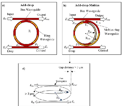
shift [33-35]. The Add-drop configuration consist of one ring waveguide attached between two bus waveguide and has two coupling region as in Figure 1. The system comprises of two input ports as input and add ports and two output ports as output and drop port. The optical field for input and control port are written as 𝐸𝑖𝑛 and𝐸c.
Figure 1 Schematics MRR system where a) Add-drop MRR configuration b) Add-drop Mobius MRR configuration and c) extension view of Add-drop Mobius MRR configuration
The fractional amount of the optical field coupled into the ring and Mobius ring waveguide as the reach the coupling region due to the scattering of evanescent waveguide. The coupling parameters are
obtained as
1,2 1
i i i
iS
and
1,2 1 1 1 1 i
C
Ci are the cross and self-coupling parameters. These parameters can be derive using the coupling theory [2]. The subscript 1 and 2 of each symbols shows the parameters belong to coupling region 1 and 2 respectively. For the output and drop port are designated as 𝐸𝑜𝑢𝑡 and 𝐸drrespectively as shown in Figure 2. For Add-drop MRR, The circulating fields within the ring waveguide exhibit the half-pass phase shift
1/ 2 exp
(
L/ 4iknL/ 2) is occurs as the pulse travel inside the waveguide which pass through semi-circle propagation trails as the yellowed arrow in Figure 1. In contrast for Add-drop Mobius MRR, the circulating fields experience extra phase shift
R2
exp
(
L
R2/ 2
ikn
L
R2)
as it propagate within the inner radius R2 of the Mobius waveguide after travelling along outer radius R1. The complex phase shifti
comprise of nonlinear Kerr effect as:2 1 0 2
(
m)
eff
E
i
knL
k n
n
L
A
(2)Here n0 is linear refractive index, n2 is nonlinear refractive index, Aeff is effective area and |E1m|2 is circulating power. The coupling matrix for coupling region 1 and 2 are introduced as:
1 1 1 1 1
iS
C
M
C
iS
(3)2 2 2 2 2
iS
C
M
C
iS
(4)Thus, the propagation field equations of both coupling region and the phase shift of the circulating field within the resonator waveguides can be written in transfer matrix form as Equations (5) to (7). The subscript m is added to designate the electric fields in Mobius waveguide. Add-drop
1 1 4,
in outE
E
M
E
E
Add-drop Mobius
1 1 4 m in out mE
E
M
E
E
(5)
3 2 2 , c dr E E ME E
3 1 2 m c dr mE
E
M
E
E
(6)1/ 2 2 1 1/ 2 4 2 0 , 0 E E E E
2 1 1/ 2
4 3 1/ 2 2
0
0
m R
m m R R
E E E E
(7)where the phase shift of Add-drop MRR 𝜉1/2 is identical
with outer radius phase shift of Add-drop Mobius MRR
𝜉𝑅1/2. 𝜉𝑅2 is the inner radius phase shift of the Mobius
MRR configuration. The expansion of the transfer matrix is used to derive the optical transfer functions of both MRR configuration as:
Add-drop,
1 2 1/ 2 1 2
1 2 1 2
1 1
out In c
S S
C C
E E E
C C C C
(8) Add-drop Mobius,2 1/ 2 2 1 2 1 2
1 2 1 2 1 2 1 2
1 1
R R
R R
out In c
R R R R
iS
C C
E E E
C C C C
(9)3.0 COUPLING VARIATION OF OPTICAL
BISTABILITY
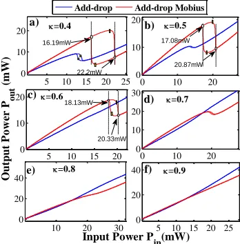
The modelled system has been developed based on the insertion of soliton pulse into Add-drop Mobius and Add-drop MRR configuration. The radius of Add-drop Mobius is set as 5 µm and 4.5 µm for inner and outer radius respectively. The comparison has been performed towards Add-drop MRR with 5 µm radius. In Figure 2, the optical hysteresis loop is obtained by varying the coupling coefficients with κi = 0.4, 0.5, 0.6, 0.7, 0.8, and 0.9 for both the coupling regions of the Add-drop filter and Add-drop Mobius configuration. The hysteresis widths of the optical bistability in Add-drop Mobius MRR configuration are reduced to 6.01 mW, 3.79 mW and 2.2 mW for an increase of the coupling coefficient as 0.4, 0.5, and 0.6 respectively. The result shows that the lower coupling coefficient produces a higher output switching power ΔPswicth. For Add-drop Mobius configuration the optical bistability are obtained with coupling coefficients of 0.4, to 0.6 and the two threshold (on and off ) of the hysteresis loop is obtained for higher input ranges of bistability. The Add-drop Mobius configuration is able to generate hysteresis loop on input-output relation with
off and on threshold powers as when it is operated with coupling coefficients of 0.4 and 0.5 which has 17.36mW, 21.03mW and 18.37mW, 19.55mW as depicts by the yellow rectangular dots in Figure 1 a) and b) respectively. For 0.6 coupling, the hysteresis loop of bistability consists of 19.90 mW on and 18.81 mW off operations of input threshold powers.
At output port of Add-drop Mobius configuration, the increase in coupling coefficients as 0.4, 0.5, and 0.6 causes a decrease in output switching power of 9.47 mW, 8.34 mW and 6.01mW respectively. When the coupling coefficient in increased from 0.7 to 0.9, the nonlinearity of input-output relation is decreased. The nonlinearity of input-output relation can be observed up to coupling coefficient of 0.8 for Add-drop Mobius configuration. This is better than the Add-drop filter configuration since it is able to have nonlinearity relation, when the coupling coefficient can be increased up to 0.5. For the coupling coefficient variation, the Add-drop filter configuration has a reduction in output switching power for the bistable signal for an increase in coupling coefficient. It shows no hysteresis loop for coupling coefficients from 0.4 to 0.9. The Add-drop Mobius configuration can be operated with the presence of optical bistability with an increment of coupling coefficient up to 0.6. The result shows that the increase in coupling coefficient reduces the nonlinearity of the MRR system for both configurations. The higher evanescent field coupled into the ring waveguide reduces the optical bistability performance with a decrease in output switching power, hysteresis loop area and an increase in the threshold power.
In the simulations, the coupling variations of Add-drop Mobius and Add-drop filter MRR configurations were performed by increasing the value of coupling coefficients κ within the self-coupling and cross-coupling parameters for both cross-coupling regions simultaneously. Basically, the change of the coupling coefficient affects the value of self-coupling and cross-coupling parameter in an inverse manner. The increase in coupling coefficients will enhance the cross-coupling and decreased the self-coupling parameter. The increase in coupling coefficient for the higher evanescence field of the optical pulse being coupled into another waveguide is not conducive for the pulse to resonate and build-up within the ring waveguide.
Figure 2 The input-output power relation of coupling coefficients variation in Add-drop filter and Add-drop Mobius configurations κi where i=0.4, 0.5, 0.6, 0.7, 0.8, and 0.9
In Figure 2, the properties of optical bistable hysteresis loop were reduced due to the higher evanescence wave coupled to the second bus waveguide at the control and drop port before making a complete roundtrip. Although, there is another source of optical bright soliton pulse coupled into the ring waveguides of Add-drop Mobius configuration, the MRR system still loses a high fractional amount of intensity after it propagates as a feedback to the first bus waveguide. The consider Equation (8) and Equation (9), numerator part of the output electric fields isEIn
C1C2 R1 R2
E iSc
2 R1/ 2 R2
The increase in coupling coefficient reduces the output of the nonlinear effect with the phase shift due to a decrease of the self-coupling parameters 𝐶2,1. The
increase of cross-coupling parameters in the second term of the numerator part contributes to a decrease of output power. Thus, the coupling coefficient is one of key parameter that control the hysteresis loop properties. Table 1 shows the threshold power, output switching power, and hysteresis width for add-drop mobius and add-drop filter configurations.
5 10 15 20 25 0
10 20a)
0 10 20
0 10 20
b)
5 10 15 20 0
10 20
Output
P
o
w
er
P o
u
t
(m
W)
c)
0 10 20
0 10 20 30
d)
10 20 30 0
20 40
Input Power Pin(mW)
e)
5 10 15 20 25 0
20 40f)
Add-drop Add-drop Mobius
=0.5
=0.9
=0.7
=0.8
=0.4
17.08mW
20.87mW 22.2mW
18.13mW
20.33mW 16.19mW
Table 1 Threshold powers, output switching powers ΔPswitch, and hysteresis width for Add-drop Mobius and Add-drop filter
configurations as a function of coupling coefficients
Variation
Threshold Power Pth
(mW) ΔPswitch (mW) = Pon - Poff Hysteresis Width W(mW) hys All-pass All-pass M All-pass All-pass M All-pass All-pass M
Coupling
0.4 on = 13.21 off = 15.51
on = 17.36
off = 21.03 4.79 9.47 1.70 6.01
0.5 N H onoff = 18.37 = 19.65 N H 8.34 N H 3.79
0.6 N H onoff = 19.90 = 18.81 N H 6.01 N H 2.2
0.7 N H N H N H N H N H N H
0.8 N H N H N H N H N H N H
0.9 N H N H N H N H N H N H
4.0 CONCLUSION
The controllable nonlinear switching operation in the optical bisatbility range is performed using 50 mW input bright soliton pulse within drop and Add-drop Mobius MRR configurations. The coupling coefficient is used as the key parameter for controlling the hysteresis loop properties of optical bistability. The variation of coupling coefficient has been performed to investigate the behavior of optical bistable hysteresis loop. For 0.4 coupling coefficient, both MRR configurations shows highest properties of hysteresis loop based on hysteresis width and switch power. The Add-drop Mobius MRR generated a bistable signal with 6.01 mW hysteresis width, and 9.47 mW output switch power with optimized radius of 5 µm outer and 4.5 m inner ring parts with 50 mW controlled power and input power. Resuls show that Add-drop Mobius MRR configuration provides higher nonlinearity as compared to the conventional Add-drop configuration. The implementation of Mobius ring waveguide is found as one of the methods for miniaturizing the design of MRR system.
Acknowledgement
We would like to thank the Laser Centre, Ibnu Sina Institute for Scientific & Industrial Research, Universiti Teknologi Malaysia and King Mongkut’s Institute of Technology Lankrabang, Thailand for providing research facilities. This research work has supported by UTM’s Potential Academic Staff vot. 01K80 and Ministry of Higher Education Malaysia.
References
[1] Banerjee, S., Mitra, M. and Rondoni, L. 2011. Applications of Chaos and Nonlinear Dynamics In Engineering. Springer Science & Business Media.
[2] Saleh, B. E. and Teich, M. C. 2007. Fundamentals of Photonics. Wiley Series in Pure an Applied Optics. New Jersey. 1062-1063.
[3] Fushimi, A. and Tanabe, T. 2014. All-Optical Logic Gate Operating with Single Wavelength. Optics Express. 22(4): 4466-4479.
[4] Grieco, A., Slutsky, B., Tan, D. T., Zamek, S.,Nezhad, M. P. and Fainman, Y. 2012. Optical Bistability in a Silicon Waveguide Distributed Bragg Reflector Fabry–Perot Resonator. Journal of Lightwave Technology. 30(14): 2352-2355.
[5] Krstic, M. M., Crnjanski, J. V. and Gvozdic, D. M. 2012. Injection Power and Detuning-Dependent Bistability in Fabry–Perot Laser Diodes. Selected Topics In Quantum Electronics. IEEE Journal. 18(2): 826-833.
[6] Zang, Z. 2012. Numerical Analysis of Optical Bistability Based on Fiber Bragg Grating Cavity Containing a High Nonlinearity Doped-Fiber. Optics Communications. 285(5): 521-526.
[7] Zang, Z. G. and Zhang, Y. J. 2012. Low-Switching Power (< 45 mw) Optical Bistability Based on Optical Nonlinearity of Ytterbium-Doped Fiber with a Fiber Bragg Grating Pair. Journal of Modern Optics. 59(2): 161-165.
[8] Andalib, P. and Granpayeh, N. 2009. All-Optical Ultracompact Photonic Crystal AND Gate Based on Nonlinear Ring Resonators. JOSA B. 26(1): 10-16.
[9] Li, J. H. 2007. Controllable Optical Bistability in a Four-Subband Semiconductor Quantum Well System. Physical Review B. 75(15): 155329.
[10] Daud, S., Ueamanapong, S., Srithanachai, I., Poyai, A., Niemcharoen, S., Ali, J. and Yupapin, P. P. 2012. Particle Accelerator Using Optical Tweezers for Photodetector
Performance Improvement. IEEE Transaction on
Nanotechnology. 11(6): 1087-1092.
[11] Dingel, B., Ye, B., Cui, W. L. and Madamopolous, N. 2013. High Performance Microring Resonator (MRR)-Based Optical Filter with Reduced Group Delay and Simplified Center-Wavelength Control. ICPS2013: International Conference On Photonics Solutions. 8883.
[12] Aziz, M. S., Jukgoljan, B., Daud, S., Tan, T. S., Ali, J. and Yupapin, P. P. 2013. Molecular Filter On-Chip Design for Drug Targeting Use. Artificial Cells, Nanomedicine, and Biotechnology. 41(3): 178-183.
[13] Bahadoran, M., Noorden, A. F. A., Chaudhary, K., Mohajer, F. S., Aziz, M. S., Hashim, S., Ali, J. and Yupapin, P. P. 2014. Modeling and Analysis of a Microresonating Biosensor for Detection Of Salmonella Bacteria in Human Blood. Sensors. 14(7): 12885-12899.
using Microring Resonator. Artificial Cells, Nanomedicine, And Biotechnology. (0): 1-7.
[15] Daud, S., Idrus, S. M. and Ali, J. 2015. Simulation of Optical Soliton Conrol in Micro and Nanoring Resonator Systems. Springer Briefs in Physics.
[16] Wen, H., Kuzucu, O., Hou, T. G.,Lipson, M. and Gaeta, A. L. 2011. All-Optical Switching of a Single Resonance in Silicon Ring Resonators. Optics Letters. 36(8): 1413-1415.
[17] Bahadoran, M., Ali, J. and Yupapin, P. P. 2013. Ultrafast All-Optical Switching Using Signal Flow Graph for PANDA Resonator. Applied Optics. 52(12): 2866-2873.
[18] Shahidinejad, A., Nikoukar, A., Amiri, I. S., Ranjbar, M., Shojaei, A., Ali, J. and Yupapin, P. P. 2012. Network System Engineering by Controlling the Chaotic Signals using Silicon Micro Ring Resonator. Computer and Communication Engineering (ICCCE), 2012 International Conference On. 2012. 765-769.
[19] Amiri, I. S., Ghorbani, S., Naraei, P. and Ahmad, H. 2015. Chaotic Carrier Signal Generation and Quantum Transmission along Fiber Optics Communication using Integrated Ring Resonators. Quantum Matter. 4(2): 151-155. [20] Noorden, A. F. A., Mohamad, A., Bahadoran, M., Chaudhary, K., Aziz, M. S.,Jalil, M. A., Ali, J. and Yupapin, P. P. 2015. All-Optical Hysteresis Switching using Mobius Configuration Microring Resonator Circuit. Jurnal Teknologi. 74(8).
[21] Bahrampour, A., Karimi, M.,Qamsari, M. A., Nejad, H. R. and Keyvaninia, S. 2008. All-Optical Set–Reset Flip–Flop based on the Passive Microring-Resonator Bistability. Optics Communications. 281(20): 5104-5113.
[22] Xu, Q.F. and Lipson, M. 2007. All-Optical Logic based on Silicon Micro-Ring Resonators. Optics Express. 15(3): 924-929.
[23] Felber, F. and Marburger, J. 1976. Theory of Nonresonant Multistable Optical Devices. Applied Physics Letters. 28(12): 731-733.
[24] Chremmos, I., Schwelb, O. and Uzunoglu, N. 2010. Photonic Microresonator Research and Applications. Springer.
[25] Kim, M. J., Cho, C. S. and Kimt, J. 2006. Miniaturized Resonator using a Planar Mobius Strip Bisected Along the Circumferential Direction. IEEE Mtt-S International Microwave Symposium Digest. 1-5: 1385-1388.
[26] Pond, J. M., Liu, S. J. and Newman, N. 2001. Bandpass Filters using Dual-Mode and Quad-Mode Mobius Resonators. IEEE Transactions on Microwave Theory and Techniques. 49(12): 2363-2368.
[27] Li, S., Ma, L., Fomin, V., Böttner, S.,Jorgensen, M. and Schmidt, O. 2013. Non-Integer Optical Modes in a Mobius-Ring Resonator. Arxiv Preprint Arxiv. 1311: 7158.
[28] Vujević, D. 2007. Application of the Möbius Strip in Electrical Engineering. Energija. 56(6): 700-711.
[29] Nawrocka, M. S., Liu, T., Wang, X. and Panepucci, R. R. 2006. Tunable Silicon Microring Resonator with Wide Free Spectral Range. Applied Physics Letters. 89(7).
[30] Koos, C., Jacome, L., Poulton, C., Leuthold, J. and Freude, W. 2007. Nonlinear Silicon-On-Insulator Waveguides for All-Optical Signal Processing. Optics Express. 15(10): 5976-5990. [31] Poon, J. K. S., Scheuer, J., Mookherjea, S., Paloczi, G. T., Huang, Y. Y. and Yariv, A. 2004. Matrix Analysis of Microring Coupled-Resonator Optical Waveguides. Optics Express. 12(1): 90-103.
[32] Aziz, M. S., Tufail, K., Khamsan, N. E., Affandi, S., Daud, S., Bahadoran, M. and Ali, J. 2015. Trapping of Gold Nanoparticle and Polystyrene Beads by Dynamic Optical Tweezers. Jurnal Teknologi. 74(8): 95-100.
[33] Agrawal, G. P. 2011. Nonlinear Fiber Optics: Its History and Recent Progress. Journal of the Optical Society of America B-Optical Physics. 28(12): A1-A10.
[34] Kivshar, Y.S. and Agrawal, G. 2003. Optical Solitons: From Fibers to Photonic Crystals. Academic Press.