i
CODE GENERATION FOR EMBEDDED REAL TIME SYSTEM
MAHMOOD AGHAJANI SIROOS TALAB
A project report submitted in fulfillment of the requirement for the award of the degree of
Master of Science (Computer Science)
Faculty of Computer Science and Information Systems Universiti Teknologi Malaysia
iii
iv
ACKNOWLEDGEMENT
v
ABSTRACT
vi
ABSTRAK
vii
TABLE OF CONTENTS
CHAPTER TITLE PAGE
DECLARATION ii
DEDICATION iii
ACKNOWLEDGEMENTS iv
ABSTRACT v
ABSTRAK vi
TABLE OF CONTENTS vii
LIST OF TABLES xii
LIST OF FIGURES xiii
LIST OF ABBREVIATIONS xvi
1 INTRODUCTION 1
1.1 Overview 1
1.2 Background of the problem 4
1.3 Problem Statement 7
1.4 Project Aim 8
1.5 Objective of Study 8
1.6 Scope of the Project 8
2 LITERATURE REVIEW 9
2.1 Overview 9
viii
2.3 Pervious Reviews on Code Generation 11 2.3.1 Comparison of Dataflow Architecture and
Real Time Workshop Embedded Coder
11
2.3.2 Reviews the Object Oriented Design on ERT
12
2.4 ERT Code Generation Frameworks 13
2.4.1 UML-RT 16
2.4.1.1 Time Managing 17
2.4.1.2 UML-RT and Code Generator Features
20
2.4.1.3 UML-RT and Robot Controller 21
2.4.2 Giotto 24
2.4.2.1 Time Managing with Giotto Compiler
26
2.4.2.2 Giotto Code Generation 31 2.4.2.3 A Giotto–Base Autonomous Helicopter System
31
2.4.3 Simulink 33
2.4.3.1 Time Managing in Simulink 35 2.4.3.2 Simulink and Code Generator
(Real-Time Workshop) Features 36
2.4.4 Labview 36
2.4.4.1 Time Managing 37
2.4.4.2 Labview Code Generation 38 2.4.5 Component oriented programming (COP) 39
2.4.5.1 Mapping of component behaviour to task and time managing
40
2.4.5.2 Analysis pattern for autonomous Mobile Robot software
40
2.4.5.3 COP Framework 41
ix
3 RESEARCH METHODOLOGY
3.1 Overviews 46
3.2 Research Methodology 47
3.3 Operational Research Framework 49
3.4 ERT Case Study 51
3.4.1 Card and Fingerprint based Time Recording Terminal
52 3.4.2 Concurrency operation in STPro 54
4 CODE GENERATOR FOR EMBEDDED REAL
TIME SOFTWARE
55
4.1 Overviews 55
4.2 Criteria of Evaluations for CBD Methodologies in ERT Code Generator
56
4.3 Reason on choosing the four criteria 58
4.4 UML RT 58
4.4.1 Iterative development in UML RT 59 4.4.2 Optimized Design Concept 60 4.4.3 Large scale development in UML RT 61 4.4.4 Integration and adaptation 62
4.5 Giotto 62
4.5.1 Iterative development 63 4.5.2 Optimization development 64 4.5.3 Large scale development 66 4.5.4 Interaction and adaptation 67
4.6 Simulink 67
4.6.1 Iterative development 68
4.6.2 Optimizing generated code 71 4.6.3 Large-scale development 76 4.6.4 Integration and adaption 77
4.7 Labview 77
x
4.7.4 Integration and adaption 81 4.8 Discussion on the Evaluation of Criteria for Code
Generators
81
4.9 Discusstion 84
5 RATIONAL ROSE REAL TIME TOOL 85
5.1 Introduction 85
5.2 Component Composition 86
5.3 Code generation 90
5.3.1 Capsule 91
5.3.2 Capsule State Diagrams 92
5.3.3 Classes 93
5.3.4 Associations 93
5.3.5 Dependency 95
5.3.6 Internal messages 95
5.4 Following criteria by Rational Rose RT 97 5.4.1 Supporting the Large Scale by Rational
Rose RT
98
5.4.2 Supporting the Iterative Development by Rational Rose RT
101
5.4.3 Discussion 102
6 COP TOOL 104
6.1 Introduction 104
6.2 COP TOOL requirement 105
6.2.1 Module 1:Component Development 105 6.2.2 Module 2:Component Integration 105 6.2.3 Module 3: Code generation 106
6.3 COP tool design 106
6.3.1 COP Composition Class Diagram 108 6.3.2 COP Code Generation class diagram 108
6.3.3 User Interface 112
xi
6.4.1 Supporting the Large Scale by COP tool 117 6.4.2 Supporting the Iterative Development by
COP tool
119
6.4.3 Discussion 121
7 CONCLUSION 124
7.1 Summary 115
7.2 Research Contribution 126
7.3 Future works 127
xii
LIST OF TABLES
TABLE NO TITLE PAGE
2.1 Evaluation based on criteria UML RT commercial system 18 2.2 Evaluation based on criteria of Giotto commercial system 27 2.3 Evaluation based on criteria Simulink commercial system 34 2.4 Summary of the comparative evaluation 45 3.1 Shows a STPro system which is provided access control
system
53
4.1 Introduce some code generation criteria 56 4.2 Summary of the comparative evaluation of frameworks
based on criteria
82
5.1 Send and received of capsule code 96
xiii
LIST OF FIGURES
FIGURE NO TITLE PAGE
1.1 Example of embedded systems 2
1.2 Embedded real time system 3
2.1 Programming model of a node processor (wikender, 1999).
14
2.2 Sequence diagram with time consuming 17
2.3 Timing diagram example 18
2.4 Capsule structure diagrams 22
2.5 Capsule structure diagrams 22
2.6 Capsule state transaction diagrams 23
2.7 Component diagram 23
2.8 Traditional control systems development process 25 2.9 The Giotto based control system development 25
2.10 Giotto time tasking diagram 26
2.11 Giotto program example (control off or controller on specification on helicopter controller)
29
2.12 Workflow of the design framework that iteratively refines code generation using schedulability
30
2.13 Time tasking on Giotto 32
2.14 There are no race conditions 32
2.15 The Giotto case block in simulink 33
xiv
2.17 Architecture of Lab VIEW in embedded real time system 39
2.18 Architecture Pattern in COP 41
2.19 Motor control composite component 42
2.20 A PID component documented in block form 43
3.1 Research Design Methodology 48
3.2 Operational Framework 50
3.3 STPro Attendence system 54
4.1 Giotto based control systems development 64 4.2 Shows the rapid prototyping development process 70
4.3 Algorithm design and prototyping 71
4.4 Three same product plot on Simulink 75
4.5 Three same product on matlab 75
5.1 class diagram in the STPro System 87
5.2 UML-RT structure model of the STPro 87
5.3 Use case diagram ofthe STPro System 88 5.4 Sequence diagram representing message sequences
between the Capsules
89
5.5 State diagram of STPro 90
5.6 Generalization in class diagram 89
5.7 Relations in class diagram 96
5.8 Relations between class and capsule 96
5.9 Relations in class diagram 97
5.10 considering the library in Rational Rose 101 6.1 Use case diagram of the composition part 107 6.2 Class diagram of the composition part 108 6.3 Class diagram of the code generation part 109
6.4 Definition of code generator 109
6.5 Header of initialization 109
6.6 Body of initialization 110
6.7 Data type declaration 110
6.8 Data declaration error by underline 110
6.9 Execution of Capsule 111
xv
6.11 Synchronization part of code generator 111
6.12 Composition of COP tool 113
6.13 Composition of COP tool and ComponentsTab 114
6.14 Code generation of COP tool 115
6.15 Tool architecture design 116
6.16 Composition of COP tool and library Tab 118 6.17 COP Library is reachable by Check Box 118
6.18 Error connections 120
xvi
LIST OF ABBREVIATIONS
COP - Component Oriented Programming
RTS - Real Time System
ERT - Embedded Real Time System
MASCOT - Modular Approach to Software framework Operation and Test
CBSE - Component Base Software System
CBD - Component Base Development
GUI - Graphical User Interface
OOP - Object Oriented Programming
AOP - Aspect Oriented Programming
RTOS - Real Time Operation System
AMR - Autonomous Mobile Robot
DSP - Digital Signal Processor
REI - Rose Extensibility Interface
ADL - Architecture Description Languages
GRT - Generic Real Time
FPGA - Field-Programmable Gate Array regexp - Reqular Expression
UI - User Interface
1
CHAPTER 1
INTRODUCTION
1.1 Overview
2
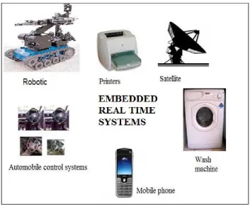
Figure 1.1: Example of embedded systems
A Real Time System (RTS) is intended to achieve the functionality under timing constraint. Real time systems are used in wide variety of applications, such as avionics, automotive, patient monitoring and etc. A missing deadline is anonymous to disastrous consequences such as loss of life in patient monitoring. So RTS must be reliable and operate with functional and non functional requirements.
3
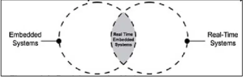
Figure 1.2: Embedded real time system
The vast majority of embedded real time systems have been managed by software. However software managing in the ERT domain is difficult and complex. For example some systems are complex like: there are more or less than 1400 interconnected software with controlled functions distributed on 80 embedded computers in some parts of car industry. So ERT software must consider high quality attributes such as safety, reliability, resource efficiency, and timing. Vehicular industry needs to improve software engineering approaches that will increase development efficiency, support handling the complexity, facilities’ safety, reliability and timing assessment (Akerholm, 2008).
Abilities of ERT systems modeling are improved by expressing the real time features such as time quality service and resources constraint. So, designers can verify and validate the features easily. In addition, designers are able to manage the complexity of real time system by high quality modeling.
4
In addition number of code errors is decreased by using the extensive automatic code generation. For the Airbus A340, automatically generated code accounted for 70% of the total (pilaud, 1998).
Moreover, total control over the software life cycle can be achieved when the specification changes during the development stage. That can be traced of monitor clearly by using the modeling and code generation tools under perfect control. Those involved pointed out the ability to very quickly and reliability deploys the modified software after a request for change.
1.2 Problem Background
The design and implementation of ERT systems should consider multiple constrains that do not comply with large component and object cased systems like business data processing system. These constrains include (Crnkovic, 2005; Goos, 2005):
i. Real time systems should cover constraints of extra-functional properties such as timing quality of service and dependability (including reliability, safety, and security). This means the system should satisfy explicit response time constraints, otherwise, it will fail.
ii. The system is safety-critical in which the functional and extra functional properties are to be statically predictable.
5
The developed framework consists of three main elements: a modified component model, a component based timing analysis approach, and a code generator.ERT frameworks can be represented by ERT tools.
Modular Approach to Software framework Operation and Test (MASCOT) is one of the oldest ERT frameworks which consider the concurrency processes such as a number of defense systems. MASCOT is applied on Rapier ground to air missile system of the British Army. In the meantime, MASCOT is appropriate for concurrency processing but there is no standard modeling for it. That’s why MASCOT is not applicable in modern ERT, because the requirements specification and software design phases are based on the traditional software lifecycle (Budgen, 1994). Furthermore, the cost of design modification was too high.
Complexity of the ERT is increased in a large scale requirement with the limitation of resources, so risks of ERT systems will be increased. Moreover, modern embedded systems must support rapid convergence of a multiple of disparate technologies.
6
However a large number of ERT modern frameworks are based on component software system (CBSE) such as OMG’s CORBA Component Model (CCM), Microsoft’s COM, COM++, Rational Rose RT, and Simulink. Advantages code generation in CBSE are:
i. Higher quality software and shorter ones together with more predictable delivery cycles. Executing models is the suitable way to find problems.
ii. Creating appropriate platform to handle the code generators on large scale. iii. Possibility of code generation modification (reverse engineering) to affect the
modeling part.
A formal notation of component interface which is enabled by component base framework such as COP provides a way to describe the interaction between components, and to verify the compatibility between components automatically. The physical processes to be controlled are continuous but the algorithms are implementing using discrete software components. Although each individual model is relatively clear, but it is difficult and complex to implement the integration of heterogeneous models based on low cost design (Chen, 2004).
7
1.3 Problem Statement
There are many ERT code generator component technologies as mentioned before, but the existing frameworks don’t possess all of the important features of Component Base Development (CBD) based ERT code generator.
The aim of this research is to identify the important criteria of the code generator framework component based in ERT systems, and then these criteria will be evaluated and compared with available CBD frameworks. Next this study will select the best framework based on these criteria to ensure the framework capability to support code generation in CBD. And then, the selected framework will be further evaluated and validated based on an ERT case study.
The main research questions are:
How can we evaluate and validate the code generation of ERT software base on
CBD approach?
What are the problems of the existing code generators?
i. What are the criteria to review ERT code generators based on CBD approach?
ii. Which code generator is the best according to ERT code generator criteria set?
iii. Is it possible to match the selected code generator and Component Oriented Programming (COP) framework?
8
1.4 Project Aim
The aim of this research is:
Evaluate the exiting ERT code generators framework in CBD approach and develop tool to support some features from the exiting code generator.
1.5 Objective of the Study
i. To identify important code generation criteria of ERT for CBD approach and, evaluate the ERT framework based on selected criteria.
ii. To implement a case study with the selected code generator framework. iii. To develop the COP environment tool to support the selected criteria.
iv. To compare the COP tool with the selected code generator tool in supporting some of criteria.
1.6 Scope of the Project
i. Focusing on the architecture of code generation details of five commercial and research ERT systems.
ii. Identify the features of code generation for component base development (CBD) on embedded real time system (ERD).
iii. Choosing an ERT system framework, and execute it based on the case study.