Bell Labs Innovations
MERLIN MAGIX™
Integrated System
System Planning
555-710-112
Comcode 108522301
Issue 2
Notice Every effort has been made to ensure that the information in this guide is complete and accurate at the time of printing. Information, however, is subject to change. See Appendix A, “Customer Support Information,” in
Feature Reference for important information.
Your Responsibility for Your System’s Security
Toll fraud is the unauthorized use of your telecommunications system by an unauthorized party—for example, persons other than your company’s employees, agents, subcontractors, or persons working on your company’s behalf. Note that there may be a risk of toll fraud associated with your telecommunications system, and, if toll fraud occurs, it can result in substantial additional charges for your telecommunications services.
You and your System Manager are responsible for the security of your system, such as programming and configuring your equipment to prevent unauthorized use. The System Manager is also responsible for reading all installation, instruction, and system administration documents provided with this product in order to fully understand the features that can introduce risk of toll fraud and the steps that can be taken to reduce that risk. Lucent Technologies does not warrant that this product is immune from or will prevent unauthorized use of common-carrier telecommunication services or facilities accessed through or connected to it. Lucent Technologies will not be responsible for any charges that result from such unauthorized use. For important information regarding your system and toll fraud, see Appendix A, “Customer Support Information,” in Feature
Reference.
Federal Communica-tions Commission Statement
This equipment has been tested and found to comply with the limits for a Class A digital device, pursuant to Part 15 of the FCC Rules. These limits are designed to provide reasonable protection against harmful interference when the equipment is operated in a commercial environment. This equipment generates, uses, and can radiate radio frequency energy and, if not installed and used in accordance with the instruction manual, may cause harmful interference to radio communications. Operation of this equipment in a residential area is likely to cause harmful interference, in which case the user will be required to correct the interference at their own expense. For further FCC information, see Appendix A, “Customer Support Information,” in Feature Reference.
Canadian Department of Communications (DOC) Interference Information
This digital apparatus does not exceed the Class A limits for radio noise emissions set out in the radio interference
regulations of the Canadian Department of Communications.
Le Présent Appareil Numérique n’émet pas de bruits radioélectriques dépassant les limites applicables aux appareils numériques de la classe A préscrites dans le réglement sur le brouillage radioélectrique édicté par le ministère des Communications du Canada.
Year 2000 Compliance The MERLIN MAGIX Integrated System is certified to be Year 2000 compliant. Additional information on this certification, and other issues regarding Year 2000 compliance, is available online at http://www.lucent.com/ enterprise/sig/yr2000.
Trademarks 5ESS, AUDIX, CONVERSANT, CentreVu, DEFINITY,
Magic On Hold, MERLIN, MERLIN LEGEND, MERLIN Mail, PARTNER, PassageWay, 10, 20L, MLX-28D, MLS-6, MLS-12, MLS-12D, MLS-18D, MLS-34D, SYSTIMAX, TransTalk, and Voice Power are registered trademarks and 4ESS, Intuity, Lucent Technologies, MERLIN MAGIX, and Prologix are trademarks of Lucent Technologies in the US and other countries.
Acculink, ACCUNET, MEGACOM, MulitiQuest, MLX-5, MLX-5D, MLX-16DP, MLX-10D, MLX-10DP, and NetPROTECT are registered trademarks of AT&T.
Microsoft, Windows, Windows NT, and MS-DOS are registered trademarks of Microsoft Corporation. ProComm and ProComm Plus are registered trademarks of DataStorm Technologies, Inc. Supra, Supra NC, StarSet, and Mirage are registered trademarks of Plantronics, Inc. UNIX is a registered trademark of UNIX System Laboratories, Inc.
PagePac is a registered trademark and Powermate and Zonemate are trademarks of DRACON, a division of Harris Corporation.
Okidata is a registered trademark of Okidata Corporation. Pipeline is a trademark of Ascend Communications, Inc.
Copyright © 2000, Lucent Technologies Document 555-710-112
All Rights Reserved Comcode 108522301
Printed in USA Issue 2
Intel and Pentium are registered trademarks of Intel Corporation. Apple and Macintosh are registered trademarks of Apple Computer, Inc. IBM is a registered trademark of International Business Machines, Inc. Novell and NetWare are registered trademarks of Novell Corporation. CLASS is a servicemark of Bellcore.
Ordering Information
For more information about Lucent Technologies documents, refer to the section entitled “Related Documents” in “About This Guide” in Feature Reference.
Support Telephone Number
In the continental US, Lucent Technologies provides a toll free customer helpline 24 hours a day. Call the Lucent Technologies Helpline at 1 800 628-2888 or your Lucent Technologies authorized dealer if you need assistance when installing, programming, or using your system. Outside the continental US, contact your local Lucent Technologies authorized representative.
Network Engineering Group
For assistance in designing a private network, call the Network Engineering Group at 1 888 297-4700.
Lucent Technologies Corporate Security
Whether or not immediate support is required, all toll fraud incidents involving Lucent Technologies products or services should be reported to Lucent Technologies Corporate Security at 1 800 821-8235. In addition to recording the incident, Lucent Technologies Corporate Security is available for consultation on security issues, investigation support, referral to law enforcement agencies, and educational programs.
Lucent Technologies Fraud Intervention
If you suspect you are being victimized by toll fraud and you need technical support or assistance, call Lucent Technologies Technical Services Organization at 1 800 628-2888.
Warranty Lucent Technologies provides a limited warranty on this product. Refer to “Limited Warranty and Limitation of Liability” in Appendix A, “Customer Support Information,” of Feature Reference.
Call: BCS Publications Center
Voice 1 800 457-1235 International Voice 317 322-6791 Fax 1 800 457-1764 International Fax 317 322-6699
Write: BCS Publications Center 2855 North Franklin Road Indianapolis, IN 46219-1385
Master Table of Contents
About This Guide
Overview . . . .xv
Intended Audience . . . .xv
How to Use This Guide . . . .xv
Terms and Conventions Used . . . xvi
■
Typographical Conventions . . . xvii
■
Product Safety Advisories. . . xvii
Security . . . xvii
Related Documents . . . xviii
How to Comment on This Guide . . . .xx
1
Before You Begin
Overview . . . 1-1
Reviewing System Components . . . 1-1
Confirming the Location of the Control Unit . . . 1-2
■
Grounding Requirements . . . 1-4
■Electrical Noise/Radio-Frequency Interference . . . 1-5
Requirements for Supporting CTI Applications . . . 1-6
■
Environmental Specifications . . . 1-8
Obtaining Telephone Company Information . . . 1-9
Obtaining User Information . . . 1-9
Obtaining a Floor Plan . . . 1-11
2
Control Unit Configuration
Overview . . . 2-1
Planning Module Placement . . . 2-1
■
Capacity for Lines/Trunks . . . 2-2
■Capacity for Extensions . . . 2-2
■Control Unit Diagram—Module Placement . . . 2-3
Recording System Operating Conditions . . . 2-5
■
Set System Date. . . 2-8
■Backup . . . 2-9
■System Consoles . . . 2-9
■Second Dial Tone Timer . . . 2-10
■Applications . . . 2-10
Numbering the System . . . 2-11
■
Identifying Extension Jacks . . . 2-11
■System Renumbering . . . 2-28
■Updating Planning Information . . . 2-32
3
Lines/Trunks
Overview . . . 3-1
Identifying Line/Trunk Jacks . . . 3-1
■
Module Types and Line/Trunk Jack Types . . . 3-2
■Jacks for Auxiliary Equipment. . . 3-8
Selecting Line/Trunk Options . . . 3-9
■
Loop-Start Reliable Disconnect . . . 3-10
■Outmode Signaling . . . 3-11
■Toll Type Prefix Required . . . 3-12
■Hold Disconnect Interval. . . 3-12
■QCC Operator to Receive Calls (Hybrid/PBX Mode Only) . . . 3-13
■QCC Queue Priority Level (Hybrid/PBX Mode Only) . . . 3-13
■Pools (Hybrid/PBX Mode Only) . . . 3-14
■Remote Access. . . 3-15
■DS1 Connectivity (100D or 100R Module) . . . 3-19
■Tie Trunks. . . 3-33
■NI-1 BRI Connectivity . . . 3-38
Assigning Lines/Trunks . . . 3-42
Assigning Telephone Buttons . . . 3-43
■
Telephones in Hybrid/PBX Mode . . . 3-44
■Telephones in Key and Behind Switch Mode . . . 3-52
■Direct-Line Consoles . . . 3-66
4
Features
Overview . . . 4-1
Telephone and Extension Features . . . 4-1
■
Queued Call Console (Hybrid/PBX Mode Only) . . . 4-3
■Pool Dial-Out Code Restriction
(Hybrid/PBX Mode Only) . . . 4-3
■
Fax Message-Waiting Receiver . . . 4-7
■Trunk-to-Trunk Transfer . . . 4-7
■HotLine . . . 4-8
■Extension Copy. . . 4-8
■Cover Ring Delay . . . 4-12
■Service Observing. . . 4-13
Operator Features . . . 4-14
■
Direct-Line Console . . . 4-15
■Queued Call Console (Hybrid/PBX Mode Only) . . . 4-15
■Direct Station Selector . . . 4-21
Group-Assigned Features . . . 4-22
■
Call Pickup Groups . . . 4-23
■Group Paging . . . 4-24
■Coverage . . . 4-24
■Group Calling . . . 4-27
System Features . . . 4-35
■
Transfer Options . . . 4-36
■Camp-On Return Time . . . 4-38
■Call Park Return Time. . . 4-38
■Automatic Callback . . . 4-38
■Extension Status . . . 4-39
■Station Message Detail Recording (SMDR) . . . 4-39
■Inside Dial Tone . . . 4-41
■Reminder Service Cancel . . . 4-41
■Calls to Unassigned Extensions . . . 4-42
■Recall Timer . . . 4-43
■Interdigit Timers . . . 4-43
■Rotary . . . 4-43
■Allowed Lists . . . 4-44
■Disallowed Lists . . . 4-45
■Call Restriction Summary . . . 4-46
■Night Service. . . 4-47
■Labeling . . . 4-50
5
Data Communications
Overview . . . 5-1
Terminology . . . 5-2
About Data and Video Communications . . . 5-3
■
Other Resource Groups . . . 5-11
■Video Systems . . . 5-12
Planning Overview . . . 5-14
Assigning Extension Jacks . . . 5-17
■
Guidelines for Digital Extension Jacks . . . 5-18
■Modem Data-Only Stations. . . 5-18
■ISDN Terminal Adapter Data-Only Stations . . . 5-19
■Local Host Computer Data Stations . . . 5-19
■LAN Workstations . . . 5-20
■Video Systems . . . 5-21
Assigning Lines/Trunks to Data and Video Stations . . . 5-22
■
Assigning Line Buttons in Hybrid/PBX Mode . . . 5-25
■Assigning Pools and Lines/Trunks (Hybrid/PBX Mode Only) . . . 5-26
■Assigning Line Buttons in Key Mode . . . 5-27
Assigning Features to Data Stations . . . 5-29
■
Pool Dial-Out Code (Hybrid/PBX Mode Only) . . . 5-30
■Calling Restrictions . . . 5-30
■Forced Account Code Entry . . . 5-31
■ARS Facility Restriction Level (Hybrid/PBX Mode Only) . . . 5-31
■System Speed Dial Codes . . . 5-32
Creating Data Hunt Groups . . . 5-32
Digital Data/Video Stations . . . 5-34
6
Modifications
Overview . . . 6-1
Preparation . . . 6-1
Adding to the System . . . 6-2
A
Customer Support Information
Support Telephone Number. . . A-1
Federal Communications Commission (FCC) Electromagnetic
Interference Information . . . .A-1
Canadian Department of Communications (DOC)
Interference Information . . . .A-1
FCC Notification and Repair Information . . . A-2
Installation and Operational Procedures . . . A-3
DOC Notification and Repair Information. . . A-4
Renseignements sur la Notification du
Security of Your System: Preventing Toll Fraud . . . .A-7
Toll Fraud Prevention. . . .A-8
■
Physical Security, Social Engineering, and
General Security Measures . . . .A-8
■
Security Risks Associated with Transferring
through Voice Messaging Systems. . . .A-9
■
Security Risks Associated with the Automated
Attendant Feature of Voice Messaging Systems . . . .A-11
■
Security Risks Associated with the Remote
Access Feature . . . .A-12
Other Security Hints . . . .A-13
■
Educating Users . . . .A-13
■Educating Operators . . . .A-14
■Detecting Toll Fraud . . . .A-14
■Establishing a Policy . . . .A-14
■Choosing Passwords . . . .A-15
■Physical Security. . . .A-16
■Limiting Outcalling. . . .A-16
Limited Warranty and Limitation of Liability . . . .A-16
■
Limitation of Liability . . . .A-17
Remote Administration and Maintenance . . . A-18
B
System Forms
Overview . . . .B-1
C
Data Forms
Data Forms . . . .C-1
D
T1/PRI Planner
T1/PRI Planner. . . .D-1
E
DS1 Connectivity Ordering
DSI Connectivity Ordering . . . .E-1
F
Unit Load Calculation
Overview . . . F-1
Unit Load Rules . . . F-1
■
Unit Loads for the Hybrid/PBX Mode . . . F-2
■Unit Loads for Key or Behind Switch Mode . . . F-2
Calculating Unit Loads . . . F-2
G
NI-1 BRI Review
NI-1 BRI Review . . . G-1
H
NI-1 BRI Provisioning
NI-1 BRI Provisioning. . . .H-1
Lucent Technologies 5ESS Switch Translations . . . .H-1
■
ISDN Capability Package “S” . . . .H-2
■Series Completion Feature Translations . . . .H-4
Northern Telecom DMS-100 Switch Translations . . . H-25
■
ISDN Capability Package “S” . . . .H-25
■Multiline Hunt Group Feature Translations . . . .H-28
Siemens SSC EWSD Switch Translations. . . H-36
■
ISDN Capability Package “S” . . . .H-36
I
Network Engineering Forms
Network Engineering Forms . . . I-1
Glossary
Glossary . . . GL-1
Index
Master List of Figures
1
Before You Begin
1-1
System Configuration for Support of CTI Applications . . . 1-7
1-2
Sample Floor Plan . . . 1-12
2
Control Unit Configuration
2-1
Sample Control Unit Diagram . . . 2-5
2-2
Extension Numbers for 2-Digit Numbering Plan . . . 2-30
2-3
Extension Numbers for 3-Digit Numbering Plan . . . 2-31
2-4
Extension Numbers for Set Up Space Numbering Plan . . . 2-31
3
Lines/Trunks
3-1
Partially Completed System Form 2c . . . 3-7
3-2
Factory-Set Assignment for 4412D+, 4424D+, and 4424LD+ Telephones
(Hybrid/PBX Mode) . . . 3-45
3-3
Factory-Set Assignment for 4406D+ Telephone
(Hybrid/PBX Mode) . . . 3-45
3-4
Factory-Set Assignment for MLX-20L and MLX-28D Telephones
(Hybrid/PBX Mode) . . . 3-45
3-5
Factory-Set Assignment for MLX-16DP Telephone
(Hybrid/PBX Mode) . . . 3-46
3-6
Factory-Set Assignment for MLX 5- and 10-Button Telephones
(Hybrid/PBX Mode) . . . 3-46
3-7
Factory-Set Assignment for ETR-34D Telephone
(Hybrid/PBX Mode) . . . 3-47
3-8
Factory-Set Assignment for ETR-18/18D Telephone
(Hybrid/PBX Mode) . . . 3-47
3-9
Factory-Set Assignment for ETR-6 Telephone
(Hybrid/PBX Mode) . . . 3-48
3-10
Factory-Set Assignment for MLS-34D Telephone
(Hybrid/PBX Mode) . . . 3-48
3-11
Factory-Set Assignment for MLS-18D Telephone
(Hybrid/PBX Mode) . . . 3-49
3-12
Factory-Set Assignment for MLS-12/12D
3-13
Factory-Set Assignment for MLS-6 Telephone
(Hybrid/PBX Mode) . . . 3-49
3-14
Factory-Set Assignment for TransTalk MDW 9031 Telephone
(Hybrid/PBX Mode) . . . 3-50
3-15
Factory-Set Assignment for Business Cordless 905 Telephone
(Hybrid/PBX Mode) . . . 3-50
3-16
Factory-Set Assignment for 4412D+, 4424D+, 4424LD+ Telephones
(Key and Behind Switch Modes) . . . 3-53
3-17
Factory-Set Assignment for 4406D+ Telephone
(Key and Behind Switch Modes) . . . 3-54
3-18
Factory-Set Assignment for MLX-20L and MLX-28D Telephones
(Key and Behind Switch Modes) . . . 3-54
3-19
Factory-Set Assignment for MLX-16DP Telephone
(Key and Behind Switch Modes) . . . 3-55
3-20
Factory-Set Assignment for MLX 5- and 10-Button Telephones
(Key and Behind Switch Modes) . . . 3-55
3-21
Factory-Set Assignment for ETR-34D Telephone
(Key Mode) . . . 3-56
3-22
Factory-Set Assignment for ETR-18/18D Telephones
(Key Mode) . . . 3-56
3-23
Factory-Set Assignment for ETR-6 Telephone
(Key Mode) . . . 3-57
3-24
Factory-Set Assignment for MLS-34D Telephone
(Key Mode) . . . 3-57
3-25
Factory-Set Assignment for MLS-18D Telephone
(Key Mode) . . . 3-58
3-26
Factory-Set Assignment for MLS-12/12D Telephones
(Key Mode) . . . 3-58
3-27
Factory-Set Assignment for MLS-6 Telephone
(Key Mode) . . . 3-58
3-28
Factory-Set Assignment for TransTalk MDW 9032Telephone
(Key Mode) . . . 3-59
3-29
Factory-Set Assignment for Business Cordless 905 Telephone
(Key Mode) . . . 3-59
3-30
Factory-Set Assignment for ETR-34D Telephone
(Behind Switch Mode) . . . 3-60
3-31
Factory-Set Assignment for ETR-18/18D Telephones
(Behind Switch Mode) . . . 3-60
3-32
Factory-Set Assignment for ETR-6 Telephone
(Behind Switch Mode) . . . 3-61
3-33
Factory-Set Assignment for MLS-34D Telephone
3-34
Factory-Set Assignment for MLS-18D Telephone
(Behind Switch Mode) . . . 3-62
3-35
Factory-Set Assignment for MLS12/12D Telephones
Behind Switch Mode) . . . 3-62
3-36
Factory-Set Assignment for MLS-6 Telephone
(Behind Switch Mode) . . . 3-62
3-37
Factory-Set Assignment for TransTalk MDW 9031 Telephone
(Behind Switch Mode) . . . 3-63
3-38
Factory-Set Assignment for Business Cordless 905 Telephone
(Behind Switch Mode) . . . 3-63
3-39
4400-Series Direct-Line Console . . . 3-66
3-40
MLX Direct-Line Console . . . 3-67
4
Features
4-1
Completed ARS Worksheet—Automatic Route Selection Tables . . . 4-54
4-2
Example 1: Form 3f, 6-Digit Table . . . 4-56
4-3
Example 2: Form 3f, Area Code Table . . . 4-57
4-4
Subpattern Example . . . 4-59
4-5
Other Digits Example . . . 4-60
4-6
Digit Absorption Example . . . 4-61
5
Data Communications
5-1
Modem Data Only . . . 5-6
5-2
MLX Voice and Modem Data . . . 5-7
5-3
MLX Voice and ISDN Terminal Adapter Data . . . 5-8
5-4
ISDN Terminal Adapter Data-Only . . . 5-9
5-5
Personal and Group Video Connections . . . 5-14
D
T1/PRI Planner
Master List of Tables
1
Before You Begin
1-1
Environmental Requirements . . .
1-21-2
Control Unit Space Requirements . . .
1-41-3
Employee Communications Survey: Description of Questions . . .
1-102
Control Unit Configuration
2-1
Application Ports . . .
2-122-2
Modules with Touch-Tone Receivers . . .
2-152-3
Touch-Tone Receivers Required by Voice Messaging Systems . . .
2-162-4
System Requirements for Touch-Tone Receivers . . .
2-162-5
TTRs Required for Primary Delay Announcement Devices . . .
2-172-6
TTRs Required for Secondary Delay Announcement Devices . . .
2-172-7
Maximum Number of Operator Positions . . .
2-202-8
Application Ports . . .
2-263
Lines/Trunks
3-1
Line/Trunk Jack Types . . .
3-23-2
Codes for Line/Trunk Jacks . . .
3-53-3
Line Compensation Settings . . .
3-223-4
Line Compensation Settings . . .
3-273-5
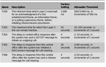
NI-1 BRI Timers . . .
3-424
Features
4-1
Features that Can Be Copied . . .
4-95
Data Communications
5-1
Data Station Configurations . . .
5-105-2
Data Forms . . .
5-155-3
System Forms . . .
5-165-4
Extension Jack Types . . .
5-176
Modifications
6-1
Adding New Trunks . . .
6-46-2
Adding Auxiliary Equipment . . .
6-4B
System Forms
B-1
System Forms . . . .
B-1C
Data Forms
C-1
Data Forms . . . .
C-1E
DS1 Connectivity Ordering
E-1
Guide to DS1 Connectivity Ordering . . . .
E-1E-2
Channel Service Unit (CSU) . . . .
E-2F
Unit Load Calculation
I
Network Engineering Forms
IMPORTANT SAFETY INSTRUCTIONS
The exclamation point in an equilateral triangle is intended to alert the user to the presence of important operating and maintenance (servicing) instructions in the literature accompanying the product.
To reduce the risk of fire, electrical shock, and injury to persons, follow these basic safety precautions when installing telephone equipment:
■ Read and understand all instructions.
■ Follow all warnings and instructions marked on or packed with the product. ■ Never install telephone wiring during a lightning storm.
■ Never install a telephone jack in a wet location unless the jack is specifically designed for wet
locations.
■ Never touch uninsulated telephone wires or terminals unless the telephone wiring has been
disconnected at the network interface.
■ Use caution when installing or modifying telephone lines.
■ Use only Lucent Technologies-manufactured MERLIN MAGIX Integrated System circuit modules,
carrier assemblies, and power units in the MERLIN MAGIX Integrated System control unit.
■ Use only Lucent Technologies-recommended/approved MERLIN MAGIX Integrated System
accessories.
■ If equipment connected to the TDL telephone modules (412 LS-ID-TDL and 024 TDL), the MLX
telephone modules (008 MLX, 408 GS/LS-ID-MLX, and 016 MLX), or the ETR telephone module (016 ETR) is to be used for in-range out-of-building (IROB) applications, IROB protectors are required.
■ Do not install this product near water—for example, in a wet basement location. ■ Do not overload wall outlets, as this can result in the risk of fire or electrical shock.
■ The MERLIN MAGIX Integrated System is equipped with a 3-wire grounding-type plug with a
third (grounding) pin. This plug will fit only into a grounding-type power outlet. This is a safety feature. If you are unable to insert the plug into the outlet, contact an electrician to replace the obsolete outlet. Do not defeat the safety purpose of the grounding plug.
■ The MERLIN MAGIX Integrated System requires a supplementary ground.
■ Do not attach the power supply cord to building surfaces. Do not allow anything to rest on the
power cord. Do not locate this product where the cord will be abused by persons walking on it.
■ Slots and openings in the module housings are provided for ventilation. To protect this equipment
from overheating, do not block these openings.
■ Never push objects of any kind into this product through module openings or expansion slots, as
■ Unplug the product from the wall outlet before cleaning. Use a damp cloth for cleaning. Do not use cleaners or aerosol cleaners.
■ Auxiliary equipment includes answering machines, alerts, modems, and fax machines. To connect one of these devices, you must first have a Multi-Function Module (MFM).
■ Do not operate telephones if chemical gas leakage is suspected in the area. Use telephones located in some other safe area to report the trouble.
■ To eliminate the risk of personal injury due to electrical shock, DO NOT attempt to install or remove an MFM from your MLX telephone. Opening or removing the module cover of your telephone may expose you to dangerous voltages.
■ ONLY an authorized technician or dealer representative shall install, set options, or repair an MFM.
SAVE THESE INSTRUCTIONS
Overview
Overview
0The MERLIN MAGIX Integrated System is an advanced digital switching system that integrates voice and data communications features. Voice features include traditional telephone features, such as Transfer and Hold, and advanced features, such as Group Coverage and Park. Data features allow both voice and data to be transmitted over the same system wiring.
Intended Audience
0This guide provides detailed information about system planning. It is intended for use by anyone who works with customers to plan, coordinate, and implement a system, including support personnel, sales representatives, and account executives. It is also intended for technicians who are responsible for system installation, maintenance, and troubleshooting.
How to Use This Guide
0This guide has been designed to provide optimal assistance to you in completing the planning forms—for example:
1. Since some chapters and/or sections apply to one or another of the configurations (Key or Behind Switch, Hybrid/PBX, or data communications), these sections are clearly marked—for example, “Hybrid/PBX Only.” Also, you are alerted to proceed to the next appropriate section, or to skip chapters or sections that do not apply to your particular system. Proceed through this guide as appropriate.
2. A list of forms or information that will be needed for particular procedures appears at the beginning of each chapter and section.
3. Where appropriate, examples of completed forms are included so you can confirm what you have done.
Since this guide assumes that you are familiar with the system, detailed information about equipment, features, and programming are not included. Refer to the following documentation for additional information:
■ System Programming gives procedural instructions for programming system features.
‘‘Related Documents,” later in this section, provides a complete list of system documentation, together with ordering information.
In the USA only, Lucent Technologies provides a toll free customer Helpline 24 hours a day. Call
the Helpline at 1 800 628-2888 (consultation charges may apply), or contact your Lucent Technologies representative if you need assistance when installing, programming, or using your system.
Outside the USA, if you need assistance when installing, programming, or using your system,
contact your Lucent Technologies authorized representative.
Terms and Conventions Used
0The terms described here are used in preference to other, equally acceptable terms for describing communications systems.
Lines, Trunks, and Facilities
0Facility is a general term that designates a communications path between a telephone system and
the telephone company central office. Technically, a trunk connects a switch to a switch—for example, the MERLIN MAGIX Integrated System to the central office. Technically, a line is a loop-start facility or a communications path that does not connect switches—for example, an intercom line or a Centrex line. In actual usage, however, the terms line and trunk are often applied interchangeably. In this guide, we use line/trunk and lines/trunks to refer to facilities in general. Specifically, we refer to digital facilities. We also use specific terms such as Personal Line,
ground-start trunk, Direct Inward Dialing (DID) trunk, and so on. When you talk to personnel at your local
telephone company central office, ask them which terms they use for the specific facilities they connect to your system.
Some older terms have been replaced with newer terms, as follows:
Old Term New Term
trunk module line/trunk module trunk jack line/trunk jack
station extension
station jack extension jack
analog data station modem data workstation digital data station terminal adapter workstation
7500B data station ISDN terminal adapter data workstation digital voice and analog data station MLX voice and modem data workstation analog data-only station modem data-only workstation
digital data-only station terminal adapter data-only workstation 7500B data-only station ISDN terminal adapter data-only workstation digital voice and digital data station MLX voice and terminal adapter workstation
Security Certain type fonts and styles act as visual cues to help you rapidly understand the information presented:
Product Safety Advisories
0Throughout these documents, hazardous situations are indicated by an exclamation point inside a triangle and the word CAUTION or WARNING.
WARNING:
Warning indicates the presence of a hazard that could cause death or severe personal injury if the hazard is not avoided.
CAUTION:
Caution indicates the presence of a hazard that could cause minor personal injury or property damage if the hazard is not avoided.
Security
0Certain features of the system can be protected by passwords to prevent unauthorized users from abusing the system. You should assign passwords wherever possible and limit distribution of such passwords to three or fewer people.
Nondisplaying authorization codes and telephone numbers provide another layer of security. Throughout this guide, toll fraud security hazards are indicated by an exclamation point inside a triangle and the words SECURITY ALERT.
Convention Example
Italics or bold indicate emphasis. It is very important that you follow these steps.
WARNING: Do not remove modules from the carrier without following proper procedures.
Italics also set off special terms. The part of the headset that fits over one or both ears is called a headpiece. Plain constant-width type indicates text
that appears on the telephone display or PC screen, as well as characters you dial at the telephone or type at the PC.
Choose ExtProgfrom the display screen.
SECURITY ALERT:
Security Alert indicates the presence of a toll fraud security hazard. Toll fraud is the unauthorized use of your telecommunications system, or use by an unauthorized party (e.g., persons other than your company’s employees, agents, subcontractors, or persons working on your company’s behalf). Be sure to read “Your Responsibility for Your System’s Security” on the inside front cover of this guide and ‘‘Security of Your System: Preventing Toll Fraud’’ in Appendix A, ‘‘Customer Support Information.”
Related Documents
0The documents listed in the following table are part of the MERLIN MAGIX documentation set. Within the continental United States, contact the Lucent Technologies BCS Publications Center by calling 1 800 457-1235.
Document No. Title
System Documents:
555-710-100 Customer Documentation Package:
Consists of paper versions of the System Manager’s Quick
Reference, the Feature Reference, and System Programming
555-710-110 Feature Reference
555-710-111 System Programming
555-710-112 System Planning
555-710-113 System Planning Forms
555-710-119 System Manager’s Quick Reference
555-610-150 MERLIN LEGEND® Communications System, Release 6.1, Network Reference
555-710-800 Customer Reference CD-ROM:
Consists of the System Manager’s Quick Reference, the
Related Documents
Telephone User Support:
555-710-123 (U.S. English)
4400/4400D Telephone User’s Guide
555-710-123FRC (Canadian French)
4400/4400D Telephone User’s Guide
555-710-127 (U.S. English)
4406D+, 4412D+, 4424D+, and 4424LD+ Telephone User’s Guide
555-710-127FRC (Canadian French)
4406D+, 4412D+, 4424D+, and 4424LD+ Telephone User’s Guide
555-660-122 MLX Display Telephone User’s Guide
555-630-150 MLX- 5D®, MLX-10D ®and MLX-10DP® Display Telephone Tray Cards (5 cards)
555-630-152 MLX-28D® and MLX-20L® Telephone Tray Cards (5 cards)
555-660-124 MLX-5® and MLX-10® Nondisplay Telephone User’s Guide
555-630-151 MLX-5® and MLX-10® Nondisplay Telephone Tray Cards (6
cards)
555-630-155 MLX-16DP® Display Telephone Tray Cards (5 cards)
555-670-151 MLS and ETR Telephone Tray Cards
555-670-152 MLS and ETR Telephone Tray Cards (16 cards)
555-660-126 Single-Line Telephones User’s Guide
555-660-138 MDC and MDW Telephones User's Guide
System Operator Support:
555-710-134 Digital Direct LIne Console Operator’s Guide
555-710-136 Digital Queued Call Console Operator’s Guide
Miscellaneous User Support:
555-661-130 Calling Group Supervisor and Service Observer User Guide
How to Comment on This Guide
0We welcome your comments, both positive and negative. Please use the feedback form on the next page to let us know how we can continue to serve you. If the feedback form is missing, write directly to:
Documentation Manager Lucent Technologies
211 Mount Airy Road, Room 2W-330 Basking Ridge, NJ 07920
Documentation for Qualified Technicians:
555-661-140 MERLIN LEGEND® Communications System, Release 6.1, Installation, SPM, Maintenance and Troubleshooting
555-710-142 Installation, SPM, Maintenance and Troubleshooting Supplement
555-715-116 Pocket Reference
Toll Fraud Security:
555-025-600 BCS Products Security Handbook
You may FAX your response to 908 953-6912. Thank you.
Issue 2, June 2000
Contents
1
Reviewing System Components . . . 1-1
Confirming the Location of the Control Unit . . . 1-2
■
Grounding Requirements . . . 1-4
■Electrical Noise/Radio-Frequency Interference . . . 1-5
Requirements for Supporting CTI Applications . . . 1-6
■
Environmental Specifications . . . 1-8
Obtaining Telephone Company Information . . . 1-9
Obtaining User Information . . . 1-9
Overview
1
Overview
1You should perform several tasks before you begin filling out the planning forms for the MERLIN MAGIX Integrated System:
■ Review the system’s hardware, features, and operation as defined at the time of purchase. ■ Confirm the location of the control unit.
■ Obtain the required information from the local telephone company. ■ Obtain information about telephone users and their needs.
■ Obtain or develop a floor plan of the customer’s site.
Each of these preplanning tasks is described in this chapter.
Reviewing System Components
1To tailor the system to the customer’s business, you must know the number and types of
telephones, outside lines/trunks, and adjuncts that were ordered. You also need to know how the equipment will be used—for example, which type of telephone is assigned to each employee, which consoles operators will be using, and where adjuncts will be located.
Confirming the Location of the Control Unit
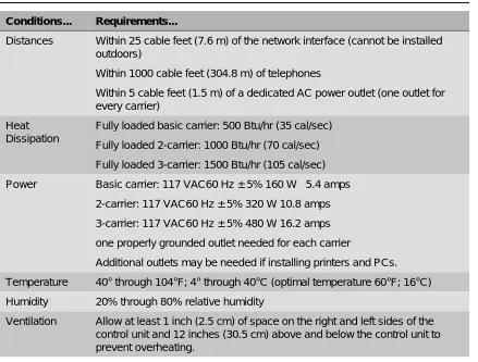
1Before installation, a room, closet, or other area must be designated where the system control unit can be mounted on the wall. The area must meet the environmental requirements in Table 1-1.
Table 1-1. Environmental Requirements
Conditions... Requirements...
Distances Within 25 cable feet (7.6 m) of the network interface (cannot be installed outdoors)
Within 1000 cable feet (304.8 m) of telephones
Within 5 cable feet (1.5 m) of a dedicated AC power outlet (one outlet for every carrier)
Heat Dissipation
Fully loaded basic carrier: 500 Btu/hr (35 cal/sec) Fully loaded 2-carrier: 1000 Btu/hr (70 cal/sec) Fully loaded 3-carrier: 1500 Btu/hr (105 cal/sec) Power Basic carrier: 117 VAC60 Hz ± 5% 160 W 5.4 amps
2-carrier: 117 VAC60 Hz ± 5% 320 W 10.8 amps 3-carrier: 117 VAC60 Hz ± 5% 480 W 16.2 amps one properly grounded outlet needed for each carrier
Additional outlets may be needed if installing printers and PCs. Temperature 40° through 104°F; 4° through 40°C (optimal temperature 60°F; 16°C) Humidity 20% through 80% relative humidity
Confirming the Location of the Control Unit
CAUTION:
The AC outlet for the control unit should not be switch-controlled. Plugging the control unit into an outlet that can be turned on and off by a switch can cause accidental disconnection of the system.
The AC outlet must be properly grounded by using an AC receptacle for a 3-prong plug.
Do not install the control unit outdoors.
Do not place the control unit near extreme heat (furnaces, heaters, attics, or direct sunlight).
Do not expose the control unit to devices that generate electrical interference (such as arc welders or motors).
Do not expose the control unit to moisture, corrosive gases, dust, chemicals, spray paint, or similar material.
Do not place anything on top of the carriers.
Do not install the control unit under any device that may drip fluid, such as an air conditioner.
It is important that the location selected for the control unit meets all of these specifications and that the backboard is in place before installation. If the location has already been selected and changes are needed, arrange for these changes before installation.
Grounding Requirements
1Proper grounding of the installation site is essential for correct and safe functioning of the system. Grounding protects the system against:
■ Lightning
■ Power surges
■ Power crosses on outside lines/trunks
■ Electrostatic discharge (ESD)
The telephone company is responsible for providing protection of outside lines/trunks at the entrance to the site. The protection should consist of:
■ Carbon blocks or gas-discharge tubes connected to an approved ground.
■ Adequate bonding of the outside line/trunk protector ground and the power-company ground.
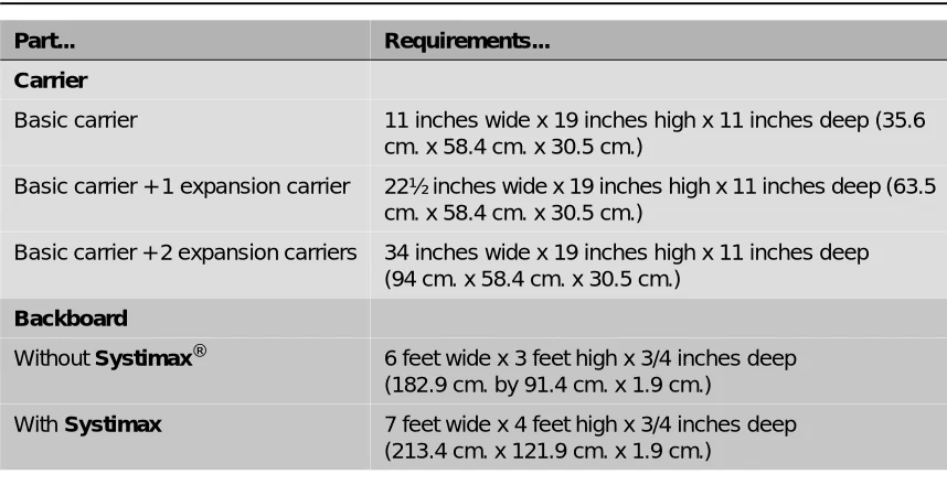
Table 1-2. Control Unit Space Requirements
Part... Requirements...
Carrier
Basic carrier 11 inches wide x 19 inches high x 11 inches deep (35.6 cm. x 58.4 cm. x 30.5 cm.)
Basic carrier + 1 expansion carrier 22½ inches wide x 19 inches high x 11 inches deep (63.5 cm. x 58.4 cm. x 30.5 cm.)
Basic carrier + 2 expansion carriers 34 inches wide x 19 inches high x 11 inches deep (94 cm. x 58.4 cm. x 30.5 cm.)
Backboard
Without Systimax® 6 feet wide x 3 feet high x 3/4 inches deep (182.9 cm. by 91.4 cm. x 1.9 cm.)
Confirming the Location of the Control Unit
CAUTION:
Improper ground can result in equipment failures and service outages. Verify that the AC power uses an approved ground for its primary ground and that all voltage-limiting devices are attached to an approved ground. Approved grounds are as follows:
■ The metal frame of the building.
■ A metal water pipe connected to an underground water pipe that is in direct contact with earth.
■ An electrode encased by at least 2 inches (5 cm) of concrete and located within and near the bottom of a concrete foundation or footing in direct contact with earth.
■ A copper ring that encircles the building and is in direct contact with earth.
For most surge occurrences, the following standard grounding requirements provide adequate lightning and power surge protection:
■ Properly wired, grounded, and bonded outside line protectors.
■ Properly wired and grounded AC outlet.
■ Properly grounded single-point ground bar.
■ Properly wired connection between single-point ground and power supply.
Electrical Noise/Radio-Frequency Interference
1In most cases, electrical noise is introduced to the system through lines/trunks or telephone cables. However, electromagnetic fields near the control unit may also induce noise in the system. The control unit and cable runs, therefore, should not be placed in areas where a high
electromagnetic field strength exists. Radio transmitters (AM and FM), television stations,
induction heaters, motors (with commutators) of 1/4 horsepower (200 watts) or greater, and similar equipment are leading causes of interference. Small tools with universal motors do not generally cause a problem when operated on separate power lines. Motors without commutators generally do not cause interference.
Field strengths below 1.0 volt per meter are unlikely to cause interference. Estimate the field strength produced by radio transmitters by dividing the square root of the emitted power (in kilowatts) by the distance from the antenna in kilometers.
Requirements for Supporting CTI
Applications
1If your site will take advantage of the Computer Telephony Integration (CTI) capabilities of the MERLIN MAGIX Integrated System, each Client Desktop must have one extension associated with a computer that is networked to a Telephony server which, in turn, is connected to the MERLIN MAGIX Integrated System through a CTI link. Figure 1-1 on page 1-7 shows the system configuration for support of CTI applications.
Use the following resources and procedures to implement a CTI application.
1. Complete the appropriate MERLIN MAGIX/Telephony Services Preliminary Survey for the application being sold.
■ The Preliminary Survey is available from the Sales and Design Support Center (SDSC) Techni-Fax (1 888 297-4700—select the appropriate prompts), or from IntraWorks at http://www.bcs.lucent.com/tech_info/sdsc/forms.
■ The survey is completed by the Account Executive (AE) and customer. 2. Contact SDSC for CTI presale support.
■ The AE should contact SDSC (1 888 297-4700—select the appropriate prompts to reach the MERLIN MAGIX split) to discuss customer requirements and potential solutions. If the CTI solution is deemed appropriate, then the AE must obtain the appropriate MERLIN MAGIX/Telephony Services Preliminary Survey.
3. Return the completed survey after the sale is made.
■ The AE will coordinate and monitor the relationship between the OEM and the customer.
■ The AE will put the DOSS Order Number on the completed survey.
■ For Phonetastic:
— Fax the completed survey to the Phonetastic™ Outsource Partner Desk (1 801 984-1120, Attention Phonetastic Outsource Coordinator).
■ The OEM will assign an Outsource Partner.
■ The OEM will establish an implementation date with the customer.
■ The OEM Outsource Partner will complete the Statement of Work for the customer. 4. Statement of Work (SOW)
■ Defines all duties performed by the OEM Outsource Partner.
■ Defines customer expectations.
■ Defines customer responsibilities.
■ Once the customer and the Outsource Partner have signed the SOW, it will be sent back to the AE to be included in the customer contract package.
5. Implementation Considerations for OEM Outsource Partners
Requirements for Supporting CTI Applications
Figure 1-1. System Configuration for Support of CTI Applications
For this configuration you must have the following equipment and software:
■ For Novell NetWare® Version 3.12, 4.1, or 4.11:
— An Intel® i386, i486, or Pentium® class computer with at least 16 MB of RAM. More memory may be needed if additional applications will be running on the server machine. See the PassageWay Telephony Services Network Manager’s Guide for more information. — MERLIN LEGEND Communications Driver® Version 1.1 or later installed (compatible with
the MERLIN MAGIX system).
— Telephony Services for NetWare software, Release 2.2.1 or later installed. — An Eicon SCOM ISDN BRI card for the CTI link.
— A free 8- or 16-bit ISA slot for the ISDN BRI card. — 5 MB of disk space on the SYS (system) volume. — Either Interrupt 2 or Interrupt 3 available.
■ For Microsoft Windows NT® 4.0 Server or Workstation (Windows NT 4.0 Server is recommended):
— A 486-class or Pentium computer with a CD-ROM and at least 32 MB of RAM and 11 MB of disk space. Additional memory may be needed if additional applications will be running on the Telephony Server machine.
— MERLIN LEGEND Windows NT Driver Version 1.0 or later installed (compatible with the MERLIN MAGIX system).
— CentreVu® Telephony Services for Windows NT software, Release 3.10 or later. — An Eicon DIVA Version 2.01 ISDN BRI card for the CTI link.
— A free 16-bit ISA slot for the ISDN BRI card.
■ System software installed on the MERLIN MAGIX Integrated System.
■ The MERLIN MAGIX Integrated System configured in Hybrid/PBX mode.
C T I L i n k
T e l e p h o n y S e r v e r
C l i e n t D e s k t o p L A N
C T I L i n k
T e l e p h o n y S e r v e r
C l i e n t D e s k t o p L A N
Public Network Incoming/Outgoing
Calls
■ An MLX module with extension ports installed in the MERLIN MAGIX Integrated System. This module must have the proper firmware or application vintage:
— If a “U” appears after the module name in the System Inventory screens, check for the proper Application Vintage:
■ 008 MLX—27 or later
■ 408 GS/LS-ID-MLX—27 or later
■ 016 MLX (Release 7.0 or later systems)—12
— If no “U” appears after the module name in the System Inventory screens, check for the proper Firmware Vintage:
■ 008 MLX—28 or later, but not 29
■ 408 GS/LS-ID-MLX—28 or later, but not 29
■ If the MERLIN MAGIX Integrated System has only one MLX extension module, you will also need System Programming and Maintenance (SPM) software to program your CTI link.
■ One extension port on an MLX module is used for the link. Select from ports 2, 3, 4, 6, 7, or 8 on 008 MLX, or 408 GS/LS-ID-MLX module. You can also select ports 2, 3, 4, 6, 7, 8, 10, 11, 12, 14, 15, or 16 on a 016 MLX module. The CTI link port cannot be the potential operator port or the console programming port.
■ For a NetWare 3.12 installation, ensure that NWSNUT.NLM, Version 4.11 or later, and TUI.NLM, Version 1.04 or later, is obtained from Novell and installed in the SYS:\SYSTEM directory.
■ For a Windows NT installation, the required .DLLs and drivers will be provided on a CD-ROM. For more information on setting up the system, see the MERLIN MAGIX Integrated System
Network Manager’s Guide.
Environmental Specifications
1If the Telephony Server platform and the MERLIN MAGIX Integrated System are to share an equipment room, the room’s environment (temperature, humidity, contaminants, EMI, AC power and grounding) must meet the more demanding set of environmental specifications for the two units. Refer to the specifications for each hardware platform for details.
If you have Version 29, replace the module with an appropriate version or, for a replacement card, call the TSO at: 1 800 628-2888.
To obtain these NLMs from Novell, access either the Novell web site
Obtaining Telephone Company Information
Obtaining Telephone Company Information
1To fill out many of the forms, especially forms involving incoming lines/trunks, you need to obtain information from the local telephone company. Before you speak with the local telephone company, make sure you understand your customer’s company requirements regarding the system. Some of the information you will need to know includes:
■ Which incoming line/trunk connects to each channel on each 100D or 100R module, and the
order in which the lines/trunks are assigned.
■ The Service Profile Identifier (SPID) and Directory Number (DN) associated with each channel
on each 800 NI-BRI module.
■ Whether the disconnect signals for loop-start lines/trunks are reliable or unreliable, and the
length of the Hold disconnect interval.
Information the local telephone company can provide includes:
■ Detailed T1 parameters ■ Detailed NI-1 BRI parameters ■ Number of digits sent on DID trunks
■ Any lines/trunks that require a toll call prefix ■ Telephone number for each incoming line/trunk
■ Type or types of incoming lines/trunks (loop-start, ground-start, and so on) ■ Any lines/trunks that are rotary-dial
Obtaining User Information
1The features and calling privileges you assign to each employee’s telephone ensure that employees get the most benefit from the system. If you were not involved in the planning and equipment-ordering for the system, you should discuss the system’s design with the customer representative who took part.
To determine calling privileges, answer the following questions:
■ Does management want to allow both local and toll calls to be made from every telephone? ■ If any telephones are restricted, are there any numbers the users should be allowed to call? ■ Are there any specific numbers (such as 900) that you want to restrict users from calling? ■ Who, if anyone, will be given Personal Lines?
■ Will access to central office lines/trunks (outside lines) be restricted to certain employees? ■ Do any departments (such as sales and service) receive frequent special calls that should
come to them directly, bypassing a system operator?
You may want to use the Employee Communication Survey Form to determine each employee’s telecommunications needs. A copy of this form is in Appendix B and is included in the forms package. Since a survey form should be completed for each user, make as many copies of the form as you need.
If it is not feasible for each employee to fill out a form, get the information you need from a knowledgeable person in each department, section, or work group. This person should have sufficient information and authority to make decisions about calling features and coverage assignments for others in the department.
Use the information in Table 1-3 to interpret and analyze the results of the Employee
Communication Survey. Numbers for items in the Required Information column correspond to question numbers on the survey.
Table 1-3. Employee Communications Survey: Description of Questions
Required Information... Description...
1. Types of lines/trunks outside lines) used
Indicates toll calling habits. In most cases, assigning a button for each line/trunk is not necessary; the use of Automatic Route Selection (Hybrid/PBX mode only) ensures that the preferred line/trunk is selected.
2. Calls covered by someone else (sender)
Suggests that this employee should be assigned as a sender in either an Individual or a Group Coverage arrangement,
particularly if calls are covered by someone other than the operator.
3. Shares lines/telephone numbers
Identifies Shared System Access buttons and/or common Personal Line appearances.
4. Covers someone else’s calls (receiver)
Suggests assignment as a receiver in someone else’s Individual or Group Coverage arrangements.
5. Shares incoming calls Identifies Calling Group needs.
6. Frequency of use Identifies heavy and light telephone users. Heavy users may benefit from additional System Access buttons and/or an additional System Access Originate Only button.
7. Data needs Identifies existing and potential data terminal and personal computer users.
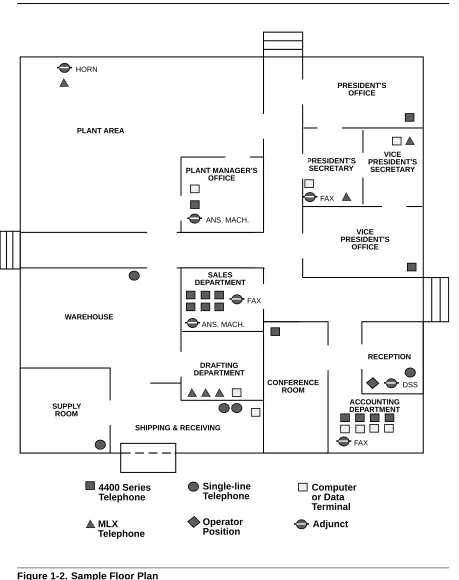
Obtaining a Floor Plan
Obtaining a Floor Plan
1You may want to use a floor plan to make planning more manageable and to ensure that the correct telephone equipment is assigned to each employee. If the customer does not already have a floor plan showing the location of system equipment, you should create one. Use the symbols shown in Figure 1-2 and the following instructions:
1. Use a large sheet of paper and sketch the office layout. The location of office walls and other partitions is important when features are assigned to telephones that must be within hearing range of each other. For example, pickup group members must be able to hear each others’ telephones ringing.
2. Indicate the location of each employee’s telephone, other locations that will have a telephone (such as a conference room), and the locations of data terminals, PCs, and host computers. 3. Indicate the type of telephone at each location, using an abbreviation that includes the number
of programmable buttons. For example, write /' at large-display, 24-button 4400-Series telephones; ' for small-display, 24-button 4400-Series telephones; 0/; at 10-button MLX telephones; 0/;/ at 20-button MLX display telephones, and so on. 4. Indicate the type of adjunct at each location. For example, write )$;, DQDPRGHP (analog
modem), KHDGVHW, or other type of adjunct beneath the symbol.
5. Indicate any additional equipment, such as a Station Message Detail Recording (SMDR) printer, Call Accounting System device, equipment required for off-site telephones, and so on. 6. Indicate the locations where AC power is available and/or required, for example, for a
Multi-Function Module (MFM), a console with two Direct Station Selectors (DSSs), or an Integrated Services Digital Network (ISDN) terminal adapter.
The floor plan does not need to be elaborate or to scale. Keep the floor plan on hand. Refer to it during planning and complete it (by filling in extension numbers) when you get to ‘‘Numbering the System’’ in Chapter 2.
Required Information... Description...
9. Frequently dialed numbers
Identifies useful numbers for the System Speed Dial list. 10. Picks up calls Identifies the need for a Pickup group.
11. View incoming caller information
Identifies which telephone users need call screening capabilities. This service may be part of the local telephone company’s services, if available, and must be subscribed to.
Figure 1-2. Sample Floor Plan
PLANT MANAGER'S OFFICE
PRESIDENT'S OFFICE
PRESIDENT'S SECRETARY
VICE PRESIDENT'S
SECRETARY
VICE PRESIDENT'S
OFFICE
SALES DEPARTMENT
DRAFTING DEPARTMENT
CONFERENCE ROOM
RECEPTION
ACCOUNTING DEPARTMENT
SHIPPING & RECEIVING SUPPLY
ROOM
WAREHOUSE PLANT AREA HORN
ANS. MACH.
ANS. MACH. FAX
FAX
DSS
FAX
4400 Series Telephone
MLX
Single-line Telephone
Operator Position
Computer or Data Terminal
Contents
2
Planning Module Placement . . . 2-1
■
Capacity for Lines/Trunks . . . 2-2
■Capacity for Extensions . . . 2-2
Planning Form Instructions . . . 2-3
■
Control Unit Diagram—Module Placement . . . 2-3
Planning Form Instructions . . . 2-4
Recording System Operating Conditions . . . 2-5
■
Programming Equipment . . . 2-6
■System Mode . . . 2-7
■Language Selection . . . 2-7
■Automatic Maintenance Busy . . . 2-8
■Set System Date . . . 2-8
■Backup . . . 2-9
■System Consoles . . . 2-9
■Second Dial Tone Timer . . . 2-10
■Applications. . . 2-10
Numbering the System. . . 2-11
■
Identifying Extension Jacks. . . 2-11
Module Types and Extension Jack Types . . . 2-12
Touch-Tone Receivers (TTRs) . . . 2-15
Jacks for Additional Operator Positions. . . 2-20
Jacks for 4400-Series Telephones . . . 2-21
Jacks for MLX Telephones . . . 2-22
Jacks for the CTI Link Application . . . 2-24
Jacks for Tip/Ring Equipment and Applications . . . 2-25
Labels . . . 2-28
Overview
2
Overview
2After you have completed the preplanning tasks described in Chapter 1, ‘‘Before You Begin,” you can plan the control unit configuration. Planning the control unit configuration consists of the following tasks:
■ Planning Module Placement. Calculate the system’s line/trunk and extension capacity
according to the number of module types; then map out the placement of the modules on the Control Unit Diagram.
■ Recording System Operating Conditions. Note the system’s type of programming
equipment, it’s mode and language choice, and whether the Automatic Maintenance Busy feature is to be enabled or disabled.
■ Numbering the System. Decide the order in which to connect the telephones and other
equipment to the control unit based on the customer’s needs and applications. Determine whether the system-assigned extension numbers are appropriate for the customer’s business or if they need to be renumbered.
This chapter contains instructions for completing each of these tasks.
Planning Module Placement
2In addition to the processor module and power supply module, the system supports several types of line/trunk and extension modules. Deciding how to place the modules in the carriers consists of the following tasks:
■ Calculating the system’s line/trunk capacity according to module types.
■ Calculating the system’s extension capacity according to module types.
■ Mapping out module placement on the Control Unit Diagram, according to specific guidelines. This section contains instructions for each of these tasks.
Forms Needed
■ Equipment List (if available)
■ Form 1, System Planning
Capacity for Lines/Trunks
2Line/trunk capacity is the number of lines/trunks that can be connected to the control unit. This section contains instructions for calculating the systems capacity for lines/trunks, according to the system’s module types.
Planning Form Instructions
21. In the table in the Line/Trunk Capacity section of Form 1, System Planning, fill in the number of each type of line/trunk module on the appropriate line of the Number of Modules column. 2. Add the column and record the result at the bottom of the column on the System Totals line. 3. For each module type noted, multiply the value in the Number of Modules column by the value
in the Trunks Supported by Module column; write the results in the appropriate row under Total Trunks by Module Type.
4. Add the column and record the total line/trunk capacity of the system at the bottom of the column, on the System Totals line.
Capacity for Extensions
2Extension capacity is the number of extensions that can be connected to the control unit. In most cases, the number of physical jacks on the modules indicates capacity. Most loop-start and ground-start modules have one or two power-failure transfer (PFT) jacks connected to a single-line telephone in case of a power failure, and not counted in system capacity. Every four line jacks has one associated PFT jack.
One extension number is automatically assigned to each extension jack, whether or not equipment is connected to it, except for the following modules:
■ 024 TDL and 412 LS-ID-TDL Modules. Two extension numbers are assigned to each
physical extension jack.
■ 008 MLX, 016 MLX, 408 GS/LS-MLX, and 408 GS/LS-ID-MLX Modules. Two extension
numbers are assigned to each physical extension jack: the first for an MLX telephone and the second for any equipment connected to the telephone through an MFM, ISDN terminal adapter, or any 2B data desktop video endpoint.
■ 008 OPT Module. The system recognizes this module as a 012 (T/R) module. Therefore, even
Planning Module Placement This section contains instructions for calculating the system’s extension capacity according to the number of certain module types.
Planning Form Instructions
21. In the table under the Extension Capacity section of Form 1, fill in the number of each type of extension module on the appropriate line of the Number of Modules column.
■ Each 100D and 100R module is assigned 24 logical IDs, even though the module has only 1 physical trunk jack.
■ Each 800 NI-BRI module is assigned 2 logical IDs per physical trunk jack for a total of 16 logical IDs.
2. Add the column and record the result at the bottom (System Totals line).
3. For each module, multiply the value in the Number of Modules column by the value in the Physical Jacks per Module column and record the results on the appropriate line in the Physical Jacks by Module Type column.
4. Add the column and record the result at the bottom (System Totals).
5. To determine the number of extensions assigned for each module type, multiply the value in the Physical Jacks by Module Type column by the value in the Extensions Assigned column and write the results in the appropriate row in the Total Extensions Assigned column.
6. Add the column and record the result at the bottom (System Totals).
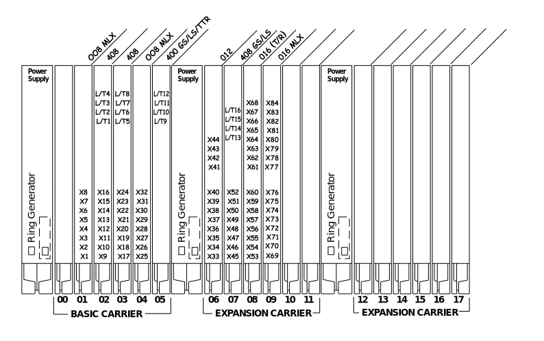
Control Unit Diagram—Module Placement
2This section describes how to use the Control Unit Diagram on Form 1 (page 2) to map the placement of the modules according to certain guidelines. Figure 2-1 on page 2-5 provides an example of a Control Unit Diagram for a system with 32 lines/trunks and 52 extensions. In addition, this section describes how to identify each jack on each module with respect to type (line/trunk or extension) and its associated logical ID. Each physical jack on the control unit is numbered sequentially from bottom to top and left to right with logical IDs as follows:
■ Extension jacks are numbered from 1 to 200.
■ Line/trunk jacks are numbered from 1 to 80.
This sequence of logical IDs is the basis for connecting components to the control unit, as well as for the assignment of extension numbers and line/trunk numbers.
Planning Form Instructions
21. On the Control Unit Diagram of Form 1 (page 2), record the type of module to be installed in each slot by writing the module name (for example, 0/;) on the slanted lines at the top of each slot. Use the following guidelines:
a. Indicate the power supply module in the far left slot of each carrier. b. Indicate the processor module in Slot 00 of the basic carrier.
c. Indicate line/trunk and extension modules in any order in Slots 01 through 17, with the following conditions:
— Group the modules in each carrier from left to right with no empty slots between modules. (The system does not recognize modules in slots that follow an empty slot; slots to the right of the last module can be left empty.)
— (Hybrid/PBX mode only) If the system includes a Queued Call Console (QCC), the first line/trunk and/or extension module must be a 412 LS-ID-TDL, 024 TDL, 408 GS/ LS-ID-MLX, 008 MLX module, or 016 MLX module.
— (All modes) Current 008 OPT and 016 (T/R) modules have built-in ring generators. The 016 (T/R) module has a REN of ≥ 4, can ring 16 ports at a time, and has no restriction on the number of jacks that can be used for applications. The 016 ETR module has a REN of 3 and can ring all tip/ring ports at the same time.
— Group all 800 DID, 100D, 100R, 800 NI-BRI, and 400EM modules together according to type; this helps save time in system programming.
2. For each line/trunk and extension jack of each module, write the type of jack (; = extension; and /7 = line/trunk) and the associated logical ID, keeping in mind the following:
■ Each 100D or 100R module is assigned 24 logical IDs, even though the module has only 1
physical trunk jack.
The Unit Load blocks above the diagram are reserved for equipment changes or maintenance. A Lucent Technologies representative or authorized dealer computes these values manually.
■ The 491D1 power supply has a maximum rating of 96 unit loads. A total of 96 4400-Series, MLX, ETR, or MLS telephones may be connected to the system.
■ If the switch is part of a private network and a tandem PRI trunk
Recording System Operating Conditions
■ Each 800 NI-BRI module is assigned 2 logical IDs per physical trunk jack for a total of 16 logical IDs.
■ The 008 OPT module is assigned 12 logical IDs, even though the module has only 8 physical extension jacks.
■ Power-failure transfer (PFT) jacks are not assigned logical IDs.
Figure 2-1. Sample Control Unit Diagram
Recording System Operating Conditions
2This section contains instructions for recording the following system operating conditions:
■ Programming equipment to be used and its extension jack assignment ■ Mode of operation
■ Language choice
■ If the system has one or more PFT telephones (maximum: 20), indicate on the Control Unit Diagram the modules that will have PFT telephones
connected to their PFT jacks; write 3)7 in the modules. A PFT telephone can be connected to a PFT jack on a 800 GS/LS-ID, 408 GS/LS-ID-MLX, or 412 LS-ID-TDL module. Touch-Tone PFT telephones must be connected to jacks with Touch-Tone lines/trunks.
■ You need a start button on a PFT telephone connected to a
ground-start trunk.
Power
Supply PowerSupply
BASIC CARRIER EXPANSION CARRIER EXPANSION CARRIER 00 01 02 03 04 05 06 07 08 09 10 11 12 13 14 15 16 17
Power Supply
Ring Gener
ator
Ring Gener
ator
Ring Gener
■ Enable and disable Automatic Maintenance Busy
■ A reminder to set the system date
■ Backup schedule
■ Identifying system console extensions
■ Second Dial Tone Timer
■ Identifying system applications
Forms Needed
2Form 1, System Planning
Programming Equipment
2Two types of equipment can be used for system programming:
■ A 4424LD+ or MLX-20L telephone identified as a system programming console. The telephone is connected to the first (lowest) extension jack (which is factory-set for system programming) on the first TDL or MLX module.
■ A personal computer with System Programming and Maintenance (SPM) software. The PC connects to the lowest jack on the processor module.
Planning Form Instructions
21. Under the Programming Equipment heading in the System Operating Conditions section on Form 1 (page 2), do either of the following:
■ If the system will use a system programming console, check the System Programming Console box.
■ If the system will use a PC with SPM software, check the PC with SPM Software box.
2. Do either of the following:
■ If you checked System Programming Console, proceed to Step 3.
■ If you checked PC with SPM Software, skip to the next section, ‘‘System Mode.” 3. To change the factory-set system programming jack, write in the new logical ID using the
information from the Control Unit Diagram.
■ In conjunction with the 4424LD+ or MLX-20L telephone and the PC, a PCMCIA card is required. Check the box labeled PCMCIA Memory Card.
Recording System Operating Conditions If you want the system programming jack to be different from that of system operators, change the programming assignment to any one of extension jacks 2 through 5 on the first TDL or MLX module in the control unit (the lowest jack on the module is extension jack 1). You fill in the extension number of the jack later.
System Mode
2The mode of operation determines how outside lines/trunks are provided to users, the types of operator consoles allowed, the features available, and how they work. Each system is registered with the Federal Communications Commission (FCC) to ope