Comcode 108762089
Issue 1
Every effort was made to ensure that the information in this book was complete and accurate at the time of printing. However, information is subject to change.
Preventing Toll Fraud
“Toll fraud” is the unauthorized use of your telecommunications sys-tem by an unauthorized party (for example, a person who is not a cor-porate employee, agent, subcontractor, or working on your company’s behalf). Be aware that there may be a risk of toll fraud associated with your system and that, if toll fraud occurs, it can result in substantial additional charges for your telecommunications services.
Lucent Technologies Fraud Intervention:
If you suspect that you are being victimized by toll fraud and you need technical assistance or support, call the Technical Service Center’s Toll Fraud Intervention Hotline at 1-800-643-2353.
Providing Telecommunications Security
Telecommunications security (of voice, data, and/or video communica-tions) is the prevention of any type of intrusion to (that is, either unau-thorized or malicious access to or use of your company’s
telecommunications equipment) by some party.
Your company’s “telecommunications equipment” includes both this Lucent product and any other voice/data/video equipment that could be accessed via this Lucent product (that is, “networked equipment”). An “outside party” is anyone who is not a corporate employee, agent, subcontractor, or working on your company’s behalf. Whereas, a “malicious party” is anyone (including someone who may be otherwise authorized) who accesses your telecommunications equipment with either malicious or mischievous intent.
Such intrusions may be either to/through synchronous (time-multi-plexed and/or circuit-based) or asynchronous (character-, message-, or packet-based) equipment or interfaces for reasons of:
• Utilization (of capabilities special to the accessed equip-ment)
• Theft (such as, of intellectual property, financial assets, or toll-facility access)
• Eavesdropping (privacy invasions to humans)
• Mischief (troubling, but apparently innocuous, tampering) • Harm (such as harmful tampering, data loss or alteration,
regardless of motive or intent)
Be aware that there may be a risk of unauthorized intrusions associated with your system and/or its networked equipment. Also realize that, if such an intrusion should occur, it could result in a variety of losses to your company (including but not limited to, human/data privacy, intel-lectual property, material assets, financial resources, labor costs, and/or legal costs).
Your Responsibility for Your Company’s Telecommunications Security
The final responsibility for securing both this system and its networked equipment rests with you – a Lucent customer’s system administrator, your telecommunications peers, and your managers. Base the fulfill-ment of your responsibility on acquired knowledge and resources from a variety of sources including but not limited to:
• Installation documents
• System administration documents • Security documents
• Hardware-/software-based security tools • Shared information between you and your peers • Telecommunications security experts
To prevent intrusions to your telecommunications equipment, you and your peers should carefully program and configure your:
• Lucent-provided telecommunications systems and their
networked equipment is either immune from or will prevent either unauthorized or malicious intrusions. Lucent Technologies will not be responsible for any charges, losses, or damages that result from such intrusions.
Federal Communications Commission Statement
Part 15: Class A Statement. This equipment has been tested and
found to comply with the limits for a Class A digital device, pursuant to Part 15 of the FCC Rules. These limits are designed to provide rea-sonable protection against harmful interference when the equipment is operated in a commercial environment. This equipment generates, uses, and can radiate radio-frequency energy and, if not installed and used in accordance with the instruction manual, may cause harmful interference to radio communications. Operation of this equipment in a residential area is likely to cause harmful interference, in which case the user will be required to corect the interference at his/her own expense.
Part 68: Network Registration Number. This equipment is registered
with the FCC in accordance with Part 68 of the FCC Rules. It is identi-fied by FCC registration number AS5USA-20411-VM-E.
Part 68: Answer-Supervision Signaling. Allowing this equipment to
be operated in a manner that does not provide proper answer-supervi-sion signaling is in violation of Part 68 rules. This equipment returns answer-supervision signals to the public switched network when:
• Answered by the called station • Answered by the attendant
• Routed to a recorded announcement that can be adminis-tered by the CPE user
This equipment returns answer-supervision signals on all DID calls forwarded back to the public switched telephone network. Permissible exceptions are:
• A call is unanswered • A busy tone is received • A reorder tone is received
Canadian Department of Communications (DOC) Interference Information
This digital apparatus does not exceed the Class A limits for radio noise emissions set out in the radio interference regulations of the Canadian Department of Communications.
Le Présent Appareil Nomérique n’émet pas de bruits radioélectriques dépassant les limites applicables aux appareils numériques de la class A préscrites dans le reglement sur le brouillage radioélectrique édicté par le ministére des Communications du Canada.
Lucent Technologies Fraud Intervention
If you suspect that you are being victimized by toll fraud and you need technical support or assistance, call BCS Technical Service Center Toll Fraud Intervention Hotline at 1 800 643-2353.
European Union Declaration of Conformity
Lucent Technologies Business Communications Systems declares that the equipment specified in this document conforms to the referenced European Union (EU) Directives and Harmonized Standards listed below:
EMC Directive 89/336/EEC Low-Voltage Directive73/23/EEC
Contents
Contents iii
About this Document vii
■ Overview vii
■ Intended Audience vii
■ How this Document Is Organized viii
■ Conventions Used in this Book viii
Safety and Security Alert Labels ix
■ Trademarks and Service Marks x
■ Related Resources xi
Documentation xi
Training xii
■ How to Make Comments About this Document xii
Conversion Checklist 1-1
■ Overview 1-1
■ Conversion Checklist 1-2
Conversion Instructions 2-1
■ Overview 2-1
Inventory the Materials 2-2
DEFINITY CLAN 2-2
DEFINITY DCIU 2-2
MERLIN LEGEND and MERLIN MAGIXs
Communication Systems 2-3
ProLogix/DEFINITY Mode Code 2-4
Identify the System’s Software
Load 2-4
Identify the LAN Card 2-6
Stop Alarm Origination 2-7
Busyout the Definity Link 2-9
For System 75, G1, G3, and R5/6 switches 2-9 For System R7 Switches with CLAN Integration 2-9 For System R8 Switches With CLAN Integration 2-10
Stop the Voice System 2-10
Backup the Lucent INTUITY System 2-11
Shutdown the Lucent INTUITY System 2-16
Stop the Voice System 2-17
Install the New Integration Software 2-18
Install INTUNIX + M or Later 2-20
Administer the Lucent INTUITY
System for the Integration 2-22
Remove Any Previous Switch
Administration on the Switch 2-23
Administer the Switch for the Switch Integration 2-24
Remove the Old DCIU Switch Hardware 2-25
Shutdown the Lucent INTUITY System 2-26
Remove and Install Hardware 2-28
MAP/5P and MAP/5PV3 Instructions 2-28
MAP/40 Instructions 2-35
MAP/40P Instructions 2-44
MAP/100 Instructions 2-50
MAP/100P Instructions 2-55
Connect the Lucent INTUITY System to the Switch 2-61
Cable the Voice Ports 2-61
Connecting the Tip/Ring Circuit Card 2-61
Cable the Switch Link 2-64
Connect the LAN Link 2-64
Connect the DCIU 2-67
Apply Power to the System 2-69
Administer and Test the LAN Link 2-70
Administer TCP/IP LAN Connectivity 2-70
Administer the LAN for Lucent INTUITY 2-70
Establish Network Addresses 2-71
Configure the Ethernet LAN Circuit Card 2-72 Reboot the System and
Attach the LAN Cable 2-74
Remap and Test the Channels 2-76
Stop the Voice System 2-77
Map Channels to Switch Extensions 2-77
Map Services to Channels for Operation 2-81
Start the Voice System 2-85
Perform Acceptance Testing 2-86
Verify Channel State 2-86
Assign the ChanTran Service and
Test the Channels 2-89
Change Extension Length 2-94
Busyout the Voice Ports 2-95
Busyout the Networking Ports 2-97
Changing a Block of Extensions
(With Extension Length Change) 2-98
Changing a Block of Extensions (Without
Extension Length Change) 2-100
Release the Voice Ports 2-103
Release the Networking Ports 2-104
Test the LAN Link 2-105
Place Test Calls to the System 2-106
Change the CAS Switch Assignment 2-106
Clear any Alarms 2-107
Assign the System Date and Time 2-108
Stop the Voice System 2-110
Backup the Lucent INTUITY System 2-111
Start the Voice System 2-114
Activate Alarm Origination 2-114
Create a Test Alarm 2-117
Replace the Nightly Backup Tape 2-118
Remove the Old Integration
About this Document
Overview
This document, Lucent INTUITY™ Messaging Solutions Release 4 Switch Integration Conversions, Issue 1, contains the procedures needed to convert a Release 4 Lucent INTUITY system switch to one of the following switches:
■ DEFINITY® CLAN
■ DEFINITY® DCIU
■ MERLIN LEGEND® or MERLIN® MAGIX™ Mode Code
■ DEFINITY® PROLOGIX™ or DEFINITY® BCS Mode Code
Intended Audience
How this Document Is Organized
This document is organized in the following chapters:
■ Chapter 1, Chapter 1, ‘‘Conversion Checklist’’
This chapter presents a checklist of procedures needed to convert Lucent INTUITY Release 4 Systems to DEFINITY CLAN, DEFINITY DCIU, MERLIN LEGEND, and ProLogix/DEFINITY Mode Code integrations.
■ Chapter 2, Chapter 2, ‘‘Conversion Instructions’’
This chapter presents the procedures needed to convert Lucent INTUITY Release 4 Systems to DEFINITY CLAN, DEFINITY DCIU, MERLIN LEGEND, and ProLogix/DEFINITY Mode Code integrations.
Conventions Used in this Book
This section describes the conventions used in this book.
■ The word “type” means to press the key or keys specified. For example, an
instruction to type the letter “y” is shown as
Type y to continue.
■ The word “enter” means to type a value and then press the enter key. For
example, an instruction to type the letter “y” and press is shown as
Enter y to continue.
■ The word “select” means to move the cursor to the desired menu item and
then press . For example, an instruction to move the cursor to the start test option a screen and to then press is shown as
Select Start Test.
■ Keys on a terminal or PC are in rounded boxes. For example, an
instruction to press the enter key is shown as
Press .
■ Two or three keys that you press at the same time on a terminal or PC are
in a series of separate rounded boxes. For example, an instruction to press and hold while typing the letter “d” is shown as
Press .
■ Function keys on a terminal, PC, or system screens, also known as soft
keys, are in round boxes followed by the function or value. For example, an instruction to press function key 3 is shown as
Press (Choices).
■ Keys that you press on a telephone keypad are in square boxes. For
example, an instruction to press the first key on a telephone keypad is shown as
Press to record a message.
■ Values, messages, field names, and prompts that appear on the system
are in typewriter-style constant-width type, as shown in the following:
Press <Enter> to continue.
■ The sequence of menu options that you must select are shown in boxes,
for example:
Start at the Lucent INTUITY Main Menu and select: :
In the above example, you would display the Lucent INTUITY Main Menu and then select Customer/Service Administration. From the
Customer/Service Administration menu, you would select Alarm Management.
■ Commands and text to type in or enter are in bold type, as in the following:
Enter change-switch-time-zone at the enter command: prompt.
■ Command variables are in bold italic type when they are part of what you
must type in and regular italic type when they are not:
Enter ch ma machine_name, where machine_name is the name of the call delivery machine you just created.
Safety and Security Alert Labels
This book uses the following symbols to call your attention to potential problems that could cause personal injury, damage to equipment, loss of data, service interruptions, or breaches of toll fraud security:
!
CAUTION:
Indicates the presence of a hazard that if not avoided can or will cause minor personal injury or property damage, including loss of data.
!
WARNING:
Indicates the presence of a hazard that if not avoided can cause death or severe personal injury.
1
> Alarm Management
!
DANGER:
Indicates the presence of a hazard that if not avoided will cause death or severe personal injury.
!
SECURITY ALERT:
Indicates the presence of a toll fraud security hazard. Toll fraud is the unauthorized use of a telecommunications system by an unauthorized party.
Trademarks and Service Marks
The following trademarked products are mentioned in books in the Lucent document set:
■ AT is a trademark of Hayes Microcomputer Products, Inc.
■ AUDIX is a registered trademark of Lucent Technologies.
■ COMSPHERE is a registered trademark of Paradyne Corp.
■ CONVERSANT Voice Information System is a registered trademark of
Lucent Technologies.
■ DEFINITY is a registered trademark of Lucent Technologies.
■ DMS-100 is a trademark of Northern Telecom Limited.
■ Dterm is a trademark of NEC Telephones, Inc.
■ Equinox is a trademark of Equinox Systems, Inc.
■ 5ESS is a registered trademark of Lucent Technologies.
■ MEGAPORT is a trademark of Equinox Systems, Inc.
■ MEGAPLEX is a trademark of Equinox Systems, Inc.
■ Meridian is a trademark of Northern Telecom Limited.
■ MERLIN LEGEND is a registered trademark of Lucent Technologies.
■ Microcom Networking Protocol is a registered trademark of Microcom, Inc.
■ Microsoft is a registered trademark of Microsoft Corporation.
■ MS is a registered trademark of Microsoft Corporation.
■ MS-DOS is a registered trademark of Microsoft Corporation.
■ Mitel is a trademark of Mitel Corporation.
■ NEAX is a trademark of NEC Telephone, Inc.
■ NEC is a registered trademark of NEC Telephone, Inc.
■ Netware is a registered trademark of Novell, Inc.
■ Novell is a registered trademark of Novell, Inc.
■ Paradyne is a registered trademark of AT&T.
■ Phillips is a registered trademark of the Phillips Screw Company.
■ Rolm is a registered trademark of International Business Machines.
■ SL-1 is a trademark of Northern Telecom Limited.
■ softFAX is a registered trademark of VOXEM, Inc.
■ SX-100 is a trademark of Mitel Corporation.
■ SX-200 is a trademark of Mitel Corporation.
■ SX-2000 is a trademark of Mitel Corporation.
■ TMI is a trademark of Texas Micro Systems, Inc.
■ UNIX is a registered trademark of UNIX Systems Laboratories, Inc.
■ Voice Bridge is a registered trademark of Voice Technologies Group, Inc.
■ VOXEM is a registered trademark of VOXEM, Inc.
■ VT100 is a trademark of Digital Equipment Corporation.
■ Windows is a trademark of Microsoft Corporation.
Related Resources
This section describes additional documentation and training available for you to learn more about installation of the Lucent INTUITY product.
Documentation
Documentation for Release 4 systems is available on CD-ROMs:
■ Lucent INTUITY Messaging Solutions Release 4 Administration, 585-310-803
■ Lucent INTUITY Messaging Solutions Release 4 Reference, 585-310-804
Documentation that can provide additional information include:
■ Lucent INTUITY Messaging Solutions Release 4 MAP/5P System Installation, 585-310-185.
■ Lucent INTUITY Messaging Solutions Release 4 MAP/5P Maintenance, 585-310-186.
■ Lucent INTUITY Messaging Solutions Release 4 MAP/40P System Installation, 585-310-196.
■ Lucent INTUITY Messaging Solutions Release 4 MAP/100 System Installation, 585-310-173.
■ Lucent INTUITY Messaging Solutions Release 4 MAP/100 Maintenance, 585-310-174.
Use the following book for information about security and toll fraud issues:
■ BCS Products Security Handbook, 555-025-600
Training
For more information on training for the Lucent INTUITY and other Lucent products, visit the Lucent Technologies training web site at www.lucenttraining.com.
How to Make Comments About this
Document
We are interested in your suggestions for improving this book. Please complete and return the reader comment card that is located at the back of the book. You can use any of your favorite mail methods:
Post Office:
Lucent Technologies
Communications Applications Group, Technical Publications Room 22-2H15
11900 North Pecos Street Denver, Colorado 80234
Email: [email protected]
Fax or voice mail: +303-538-9625
1
1
Conversion Checklist
Overview
This chapter contains a checklist of procedures needed for the Lucent INTUITY Messaging Solutions Release 4 switch integration conversions.
!
CAUTION:
Conversion Checklist
Table1-1 provides the checklist of procedures for Lucent INTUITY Release 4 System conversion to one of the following switches:
■ DEFINITY® CLAN
■ DEFINITY® DCIU
■ MERLIN LEGEND® or MERLIN® MAGIX™ Mode Code
■ DEFINITY® PROLOGIX™ or DEFINITY® BCS Mode Code
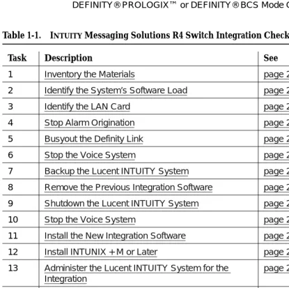
Table 1-1. INTUITY Messaging Solutions R4 Switch Integration Checklist
Task Description See ✔
1 Inventory the Materials page 2-2
2 Identify the System’s Software Load page 2-4
3 Identify the LAN Card page 2-6
4 Stop Alarm Origination page 2-7
5 Busyout the Definity Link page 2-9
6 Stop the Voice System page 2-10
7 Backup the Lucent INTUITY System page 2-11
8 Remove the Previous Integration Software page 2-14
9 Shutdown the Lucent INTUITY System page 2-16
10 Stop the Voice System page 2-17
11 Install the New Integration Software page 2-18
12 Install INTUNIX + M or Later page 2-20
13 Administer the Lucent INTUITY System for the Integration
page 2-22
14 Remove Any Previous Switch Administration on the Switch
page 2-23
15 Administer the Switch for the Switch Integration page 2-24
16 Remove the Old DCIU Switch Hardware page 2-25
17 Shutdown the Lucent INTUITY System page 2-26
18 Remove and Install Hardware page 2-28
19 Connect the Lucent INTUITY System to the Switch page 2-61
20 Apply Power to the System page 2-69
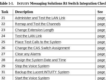
21 Administer and Test the LAN Link page 2-70
22 Remap and Test the Channels page 2-76
23 Change Extension Length page 2-94
24 Test the LAN Link page 2-105
25 Place Test Calls to the System page 2-106
26 Change the CAS Switch Assignment page 2-106
27 Clear any Alarms page 2-107
28 Assign the System Date and Time page 2-108
29 Stop the Voice System page 2-110
31 Backup the Lucent INTUITY System page 2-111
32 Start the Voice System page 2-114
33 Activate Alarm Origination page 2-114
34 Create a Test Alarm page 2-117
35 Replace the Nightly Backup Tape page 2-118
36 Remove the Old Integration Software Tapes page 2-118
Table 1-1. INTUITY Messaging Solutions R4 Switch Integration Checklist
Task Description See ✔
2
2
Conversion Instructions
Overview
This section describes how to convert INTUITY Messaging Solutions Release 4 systems to one of the following switches:
■ DEFINITY® CLAN
■ DEFINITY® DCIU
■ MERLIN LEGEND® or MERLIN® MAGIX™ Mode Code
Task 1 - Inventory the Materials
This section lists the materials needed for a conversion according to the integration type.
!
CAUTION:
Verify that the customer’s current software tapes are available in case of a system failure.
DEFINITY CLAN
For DEFINITY CLAN integration, you will need the following materials:
■ Hardware:
— LAN circuit card, if not already installed in the Lucent INTUITY system (model 8416)
— Category 5 Crossover RJ45 modular cables to connect the switch to the Lucent INTUITY system14
■ Software:
— C-LAN Switch Integration Software 1 of 1 (J1P321TE-1 L-73, PG-5Y796)
— Latest INTUNIX (J1P321TE-1-L69)
■ Documentation:
— This document
— INTUITY Messaging Solutions R4.4 LAN Integration with DEFINITY ECS, 585-313-602, Issue 1
— Switch integration planning worksheets. These worksheets, located in INTUITY Messaging Solutions Release 4 Switch Integration Conversions, 585-313-602, Chapter 2, “Switch Integration Planning”, must be completed before integrating the Lucent INTUITY system with a LAN link.
!
CAUTION:
Without the completed worksheets, you will not be able to complete this installation.
DEFINITY DCIU
For
DEFINITY DCIU integration,
you will need the following materials:■ Hardware:
— DCIU circuit card (EICON)
— IDI cable
NOTE:
7400Ds are no longer available. Therefore, conversions for systems with duplicate common controllers that require the 7400D are not supported.
■ Software: Intuity Platform DCIU Set (JIP321TE L-16, PG-5Y410)
■ Documentation:
— This document
— INTUITY Messaging Solutions Integration with System 75, DEFINITY Generics 1 & 3, and R5/6, 585-310-257, Issue 2
— Switch integration planning worksheets. These worksheets, located in INTUITY Messaging Solutions Integration with System 75,
DEFINITY Generics 1 & 3, and R5/6, 585-310-257, Issue 2, Chapter 2, “Switch Integration Planning”, must be completed before
integrating the Lucent INTUITY system with a
DEFINITY DCIU
switch
.!
CAUTION:
Without the completed worksheets, you will not be able to complete this installation.
MERLIN LEGEND and MERLIN MAGIXs
Communication Systems
For
MERLIN LEGEND and MERLIN MAGIXs Communication Systems
integration,
you will need the following materials:■ Software: Serial/In-band Switch Integration Software 1 of 1 (J1P321TE L-9,
PG-TY480)
■ Documentation:
— This document
— INTUITY integration with MERLIN LEGEND Communications System. 585-310-255, Issue 1
— Switch integration planning worksheets. These worksheets, located in INTUITY integration with MERLIN LEGEND Communications System, 585-310-255, Issue 1, Chapter 2, “Planning the Integration”, must be completed before integrating the Lucent INTUITY system with MERLIN LEGEND and MERLIN MAGIXs Communications Systems.
!
CAUTION:
ProLogix/DEFINITY Mode Code
For
ProLogix/DEFINITY Mode Code integration,
you will need the following materials:■ Software: Serial/In-band Switch Integration Software 1 of 1 (J1P321TE L-9,
PG-TY480).
■ Documentation:
— This document
— INTUITY Messaging Solutions Integration with System 75, DEFINITY Generics 1 & 3, and R5/6, 585-310-257, Issue 2
— Switch integration planning worksheets. These worksheets, located in INTUITY Messaging Solutions Integration with System 75,
DEFINITY Generics 1 & 3, and R5/6, 585-310-257, Issue 2, Chapter 2, “Switch Integration Planning”, must be completed before
integrating the Lucent INTUITY system with a ProLogix/DEFINITY Mode Code switch.
!
CAUTION:
Without the completed worksheets, you will not be able to complete this installation.
Task 2 - Identify the System’s Software
Load
The following procedure describes how to identify the system’s software load.
1. Log in to the Lucent INTUITY system as craft. 2. Press to use the at386 terminal type default.
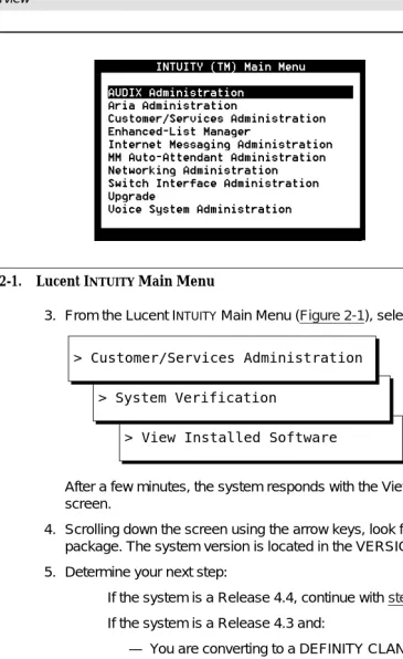
Figure 2-1. Lucent INTUITY Main Menu
3. From the Lucent INTUITY Main Menu (Figure 2-1), select:
After a few minutes, the system responds with the View Installed Software screen.
4. Scrolling down the screen using the arrow keys, look for the VM-sw package. The system version is located in the VERSION field
5. Determine your next step:
■ If the system is a Release 4.4, continue with step 6. ■ If the system is a Release 4.3 and:
— You are converting to a DEFINITY CLAN integration, update the system to a Release 4.4 and then continue with Task 3, "Identify the LAN Card".
— You are not converting to a DEFINITY CLAN integration, continue with step 6.
6. Press (Cancel) once to return to the System Verification menu.
7. Continue with Task 3, "Identify the LAN Card".
> View Installed Software > System Verification
> Customer/Services Administration
Task 3 - Identify the LAN Card
The following procedure describes how to identify the LAN card.
1. From the System Verification menu, select:
The system displays the View Installed Hardware screen (Figure 2-2).
Figure 2-2. View Installed Hardware Screen
2. Scroll down the screen using the arrow keys and locate the LAN card type. If the system does not have a LAN card installed, there is no LAN card type entry on the screen.
3. Determine your next step:
■ If the system has a LAN card, write down the LAN card type.
LAN Card: ___________________
■ If the system does not have a LAN card, continue with the step 4.
4. Press (Cancel) three times to return to the Lucent INTUITY Main Menu.
> View Installed Hardware
5. Determine your next step:
■ If the system has alarm origination, then continue with Task 4, "Stop
Alarm Origination".
■ If the system does not have alarm origination and is integrated with
a DEFINITY Communications System, Task 5, "Busyout the Definity Link" on page 2-9.
■ If the system does not have alarm origination and is not integrated
with a DEFINITY Communications System, Task 6, "Stop the Voice System" on page 2-9.
Task 4 - Stop Alarm Origination
The following procedure inactivates alarm origination so that the Lucent INTUITY system will not inform the remote support center of any alarms that occur during the conversion process.
1. Beginning at the Lucent INTUITY Main Menu (Figure 2-1), select:
The system responds with the Alarm Management screen (Figure 2-3).
Figure 2-3. Alarm Management Screen
2. Move the cursor to the Alarm Origination field.
3. Press (Choices).
The system responds with the Alarm Origination screen (Figure 2-4).
> Alarm Management
> Customer/Services Administration
Figure 2-4. Alarm Origination Menu
4. Select INACTIVE.
The system responds by changing the entry in the alarm Origination
field to INACTIVE.
5. Press (Save).
The system responds with an Information screen (Figure 2-5).
Figure 2-5. Information Screen
6. Press .
The system returns to the Alarm Management screen.
7. Press (Cancel) repeatedly to return to the Lucent INTUITY Main Menu (Figure 2-1).
8. Determine your next step:
■ If the system is integrated with a DEFINITY DCIU Communications
System, continue with Task 5, "Busyout the Definity Link".
■ If the system is not integrated with a DEFINITY Communications
System, continue with Task 6, "Stop the Voice System" on page 2-10.
F3
ENTER
Task 5 - Busyout the Definity Link
For Lucent INTUITY systems integrated with a DEFINITY Communications System, you must busyout the physical link to prevent the switch from calling out alarms.
For System 75, G1, G3, and R5/6 switches
To busyout the link, go to the Definity switch monitor, and perform the following steps:
1. Enter busy link n
where n is the number of the physical link to the Lucent INTUITY system. n may be any integer from 1 to 8.
2. Continue with Task 6, "Stop the Voice System".
For System R7 Switches with CLAN Integration
To busyout the link, perform the steps in the following two procedures:
Identify the Host Name
1. From the Lucent INTUITY Main Menu (Figure 2-1), select:
2. Locate and write down the host name that appears in the Host Name field.
3. Press (Cancel) twice to return to the Lucent INTUITY Main Menu (Figure 2-1).
4. Continue with ‘‘Busyout the Link’’.
Busyout the Link
1. Go to the Definity switch monitor and enter change communication-interface processor-channels
2. In the Destination Node column, move the cursor to the host name that you wrote down in the ‘‘Identify the Host Name’’ procedure, step 2.
3. Enter n in the Enable column.
4. Press on the numeric keypad.
5.
Continue with
Task 6, "Stop the Voice System".
> Network Addressing > TCP/IP Administration
F6
For System R8 Switches With CLAN Integration
To busyout the link, perform the steps in the following two procedures:
Identify the Host Name
1. From the Lucent INTUITY Main Menu (Figure 2-1), select:
2. Locate and write down the host name that appears in the Host Name field.
3. Press (Cancel) twice to return to the Lucent INTUITY Main Menu (Figure 2-1).
4. Continue with ‘‘Busyout the Link’’.
Busyout the Link
1. Go to the Definity switch monitor and enter change communication-interface processor-channels
2. In the Node Name column, move the cursor to the host name that you wrote down in the ‘‘Identify the Host Name’’ procedure, step 2.
3. Enter n in the Enable Eth Pt column.
4. Press on the numeric keypad.
5.
Continue with
Task 6, "Stop the Voice System".
Task 6 - Stop the Voice System
The following procedure describes how to stop the voice system.
1. Starting at the Lucent INTUITY Main Menu (Figure 2-1), select:
The system displays the Wait Time window (Figure 2-6).
> Network Addressing > TCP/IP Administration
F6
ENTER
> Stop Voice System > System Control
> System Management
Figure 2-6. Wait Time Window
2. Enter a time from 60 to 600 seconds in the Seconds field.
3. Press (Save).
The system stops the voice system and returns to the System Control screen or presents the prompt:
The Voice System has stopped.
Press ENTER to continue.
If the system presents this prompt, press to return to the System Control screen.
4. Press (Cancel) three times to return to the Lucent INTUITY Main Menu (Figure 2-1).
5. Continue with Task 7, "Backup the Lucent INTUITY System".
Task 7 - Backup the Lucent INTUITY
System
A backup is the only way to ensure the system can recover in the event of an unforeseen catastrophic failure, such as equipment or power failure, or problems with the conversion.
NOTE:
Do a backup now, especially if you just did a backup as part an upgrade to Release 4.4.
To perform a full system backup:
1. From the Lucent INTUITY Main Menu (Figure 2-1), select:
F3
ENTER
The system displays the Backup window (Figure 2-7).
Figure 2-7. Sample Backup Window
NOTE:
The screen displays fields based on the system’s configuration and may differ from this illustration. For example, the AUDIX
Announcement field can be set to No if the current announcement tape is available.
2. Enter Yes in all fields to back up all data.
3. Press (Save).
The system displays the message:
backup started
calculating the total size for the backup please wait
the total backup size is yyy MB you will need:
x yyy MB cartridge tape(s) or x y GB cartridge tape(s)
> Backup > Backup/Restore
> Customer/Services Administration
Where x is the number of blank tapes you will need and yyy is the tape capacity (for example, 525 Mb).
4. Make sure that there are enough cartridge tapes to accommodate the backup.
The system displays the message:
Verify whole backup tape(s) will double the amount of backup time.
Do you really want to verify tape(s)? (Strike y or n)
NOTE:
Verification is not necessary to ensure a good backup tape. The Lucent INTUITY system verifies a backup tape by reading back the entire set of data just written onto the tape, which doubles the total time required.
5. Press n to not verify the backup.
The system displays the following message:
please insert a tape into the tape drive to back up tape 1
press <Enter> when tape is inserted press <Esc> key to terminate the backup
6. Press the button on the upper right corner of the drive to open the drive door.
7. Insert a formatted blank tape.
8. Close the door to push in the tape.
9. Press when LED on drive is steadily.
NOTE:
If you pressed before you inserted the tape into the drive, you must press again after the tape is in the drive.
The system displays a series of messages indicating what is being stored on the backup tape.
10. If the backup is complete, continue with step 11. If the backup requires another tape, do the following:
a. Press the button on the upper right corner of the drive to open the drive door.
b. Remove the current tape, and insert the next tape.
c. Label the tape with the current date and backup data type(s).
d. Press when the tape drive is idle.
ENTER
ENTER
ENTER
When the backup is complete, the system displays the following message:
backup process has been completed successfully press any key to continue
11. Press .
12. Label all backup tapes with the current date and backup data type(s).
13. Press (Cancel) three times to return to the Lucent INTUITY Main Menu (Figure 2-1).
14. Continue with Task 8, "Remove the Previous Integration Software".
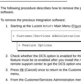
Task 8 - Remove the Previous Integration
Software
The following procedure describes how to remove the previous integration software.
To remove the previous integration software:
1. Starting at the Lucent INTUITY Main Menu (Figure 2-1), select:
2. Check whether the DCS option is enabled for this system. If it is, the feature must be re-enabled after you install the new software. Contact the remote support center to get the DCS option enabled.
3. Press (Cancel) once to return to the Customer/Services Administration menu.
4. From the Customer/Services Administration menu, select:
5. In the list of available packages, locate the previous switch integration software package that needs to be removed. Press as needed to page through the list of software packages.
Depending on the integration type, one of the following software packages in Table 2-1 need to be removed.
ENTER
F6
> Feature Options
> Customer/Services Administration
F6
> Software Remove > UNIX Management > System Management
Table 2-1. Switch Integration Software Packages That Need to be Removed
6. When you find the package number associated with the previous integration type, press CTRL-D to stop the display of packages.
7. At the prompt, enter the number of the package being removed.
!
CAUTION:
Remove only one of the packages that is listed in Table 2-1. Removing a package that is not listed in Table 2-1 can cause the conversion to fail.
Verify that you are removing the correct package, and answer y to any questions that the system displays.
8. Press q to exit the Software Remove procedure.
9. Press (Cancel) three times to return to the Lucent INTUITY Main Menu. 10. Continue with Task 9, "Shutdown the Lucent INTUITY System".
Package Name Integration Type
DCIUset X.25 protocol only to Lucent Technologies switches
LANset TCP/IP LAN connection only to Lucent Technologies switches
SWINset The following are SWINset packages:
■ NEC NEAX (serial connection)
■ Siemens HICOM (serial connection)
■ Ericsson (serial connection)
■ MERLIN LEGEND (mode code)
■ DMS100 (serial connection)
■ Intecom (serial connection)
■ Norstar (mode code)
■ System 25 (mode code)
■ 5ESS (serial connection)
■ DEFINITY Mode Code (mode code Lucent
Technologies)
VBPCset Nortel Medrian 1
RLMTLset Rolm 9751 Switches
Task 9 - Shutdown the Lucent INTUITY
System
The following procedure describes how to shut down the system.
1. Starting at the Lucent INTUITY Main Menu (Figure 2-1), select:
The system displays the Wait Time window (Figure 2-8).
Figure 2-8. Wait Time Window
2. Enter 0 (zero) for an immediate shutdown.
3. Press (Save).
The system displays the following message:
Voice system is already stopped. Shutdown started.
When the system is completely shut down, the system displays the following message.
The system is down.
Press Ctrl-Alt-Del to reboot your computer.
4. Continue with Task 10, "Stop the Voice System".
> Shutdown System > System Control > System Management
> Customer/Services Administration
Task 10 - Stop the Voice System
The following procedure describes how to stop the voice system.
1. Allow the system to boot.
2. From the Lucent INTUITY Main Menu (Figure 2-1), select:
The system displays the Wait Time window (Figure 2-9).
Figure 2-9. Wait Time Window
3. Enter a time from 60 to 600 seconds in the Seconds field.
4. Press (Save).
The system stops the voice system and returns to the System Control screen or presents the prompt:
The Voice System has stopped.
Press ENTER to continue.
If the system presents this prompt, press to return to the System Control screen.
5. Press (Cancel) twice to return to the Customer/Services Administration menu (Figure 2-1).
6. Continue with Task 11, "Install the New Integration Software".
> Stop Voice System > System Control
> System Management
> Customer/Services Administration
F3
ENTER
Task 11 - Install the New Integration
Software
The following procedure describes how to install the new switch integration software.
NOTE:
If you are installing a CLAN integration and your system not a Release 4.4, do not continue.
1. Verify that a full system backup tape is available.
This should be a current backup. In the event of a system or update failure, the backup tape is used to restore the system.
!
CAUTION:
Do not change software on the system unless you have a current backup of the original configuration.
2. From the Customer/Services Administration menu, select:
3. The system displays the Software Install menu (Figure 2-10):
Figure 2-10. Software Install Menu
4. Select Tape drive
5. Insert the new switch integration software tape into the drive (close the drive door to push in the tape).
6. Press when the tape drive is idle.
The system displays the package on this tape.
> Software Install > UNIX Management > System Management
7. At the prompt, press .
The system installs the switch integration package and displays the file names on the screen. When the installation is complete, the system displays the following message:
Insert a cartridge into tape drive 1 Type [go] when ready
or [q] to quit: (default: go)
8. Enter q
9. Remove the tape from the tape drive.
10. Press (Cancel) four times to return to the Lucent INTUITY Main Menu (Figure 2-1).
11. Remove the switch integration software tape cartridge.
12. Determine your next step:
■ If you are installing a CLAN or a DCIU integration, go to step 13. ■ if you are not installing a CLAN or a DCIU integration, go to step 15.
13. If the DCS feature was enabled before you installed the new software, you must verify that it is still enabled. Starting at the Lucent INTUITY Main Menu, select:
14. Check whether the DCS option is enabled for this system. If it is, continue with step 15. If DCS should be enabled but it is not, the feature must be re-enabled. Call the Multimedia Messaging Implementation Support (MMIS, formerly the AUCC) at 1-800-248-1234 to have the DCS feature enabled.
15. Press (Cancel) once to return to the Customer/Services Administration menu.
16. Continue with Task 12, "Install INTUNIX + M or Later".
ENTER
F6
> Feature Options
> Customer/Services Administration
Task 12 - Install INTUNIX + M or Later
The following procedure describes how to install the INTUNIX update.
1. Starting at the Customer/Services Administration menu, select:
The system displays the Software Install menu.
2. Select Tape drive from the Software Install menu.
3. Insert the Lucent INTUITY INTUNIX + M (or later) Sftw Update tape into the tape drive.
4. Press .
The system displays the message:
Installation in progress. Do not remove tape.
The following pkgs are available:
1 INTUNIX INTUITY UnixWare x.x.x Enhancement Set - Update X
Select package(s) you wish to process (or ‘all’ to process all packages). (default: all) [?,??,q]
5. Press to select all.
The system displays the message:
A version of the LAN driver is already installed. Do you want to overlay that driver and re-use the kernel options for the driver? The overlay option, which is often used during field upgrades, will preserve the network environment.
y) to overlay
q) to quit (default: quit)
Do you want to overlay the driver? > Software Install
> UNIX Management > System Management
ENTER
6. Enter y
The system displays the message:
The board type currently installed in the system is the xxxx LAN adapter.
1) 8216 LAN adapter.
2) 8416 LAN adapter.
q) To abort installation.
Please enter the board type you wish to use:
where xxxx is the board type for the system you’re upgrading.
!
CAUTION:
The board type numbers are very similar. Read the system message carefully before selecting the board type.
7. Note the board type in the first line of the system message and enter 1 or 2, as appropriate.
NOTE:
If no LAN card is installed, enter 2 or the type of LAN card that you will be installing.
The system processes the packages on the tape and displays several status messages. When the processing is completed, the system displays the following message:
Installation of INTUITY UnixWare x.x.x Enhancement Set (INTUNIX) was successful.
Insert a cartridge into Tape Drive 1. Type [go] when ready
or [q] to quit: (default: go)
8. Enter q
9. Remove the tape from the tape drive.
10. Press (Cancel) four times to return to the Lucent INTUITY Main Menu. 11. Continue with Task 13, "Administer the Lucent INTUITY System for the
Integration". The system
displays the board type of the LAN adapter installed on the platform. Use this information to select the LAN adaptor type.
Task 13 - Administer the Lucent INTUITY
System for the Integration
Administer the Lucent INTUITY system for the integration.
For: see:
DEFINITY CLAN INTUITY Messaging Solutions R4.4 LAN Integrations with DEFINITY ECS, 585-313-602, Issue 1, Chapter 4, "Lucent INTUITY System Administration for Switch Integration," page 4-1.
After administering the Lucent INTUITY system, determine your next step:
■ If you are removing a DCIU integration, continue
with Task 14, "Remove Any Previous Switch Administration on the Switch".
■ If you are not removing a DCIU integration,
continue with Task 15, "Administer the Switch for the Switch Integration" on page 2-24.
DEFINITY DCIU For DEFINITY Release 5 and 6, see INTUITY Messaging Solutions Integration with System 75, DEFINITY Generics 1 & 3, and R5/6, 585-310-257, Issue 2, Chapter 8, "Lucent INTUITY System
Administration for Switch Integration," page 8-1.
After administering the Lucent INTUITY system, continue with Task 15, "Administer the Switch for the Switch Integration" on page 2-24.
MERLIN
LEGEND/MAGIX Communications Systems
INTUITY Integration with MERLIN LEGEND Communications System, 585-310-255, Issue 1, Chapter 5, "MERLIN LEGEND Switch Administration," page 5-1.
After administering the Lucent INTUITY system, determine your next step:
■ If you are removing a DCIU integration, continue
with Task 14, "Remove Any Previous Switch Administration on the Switch".
■ If you are not removing a DCIU integration,
continue with Task 15, "Administer the Switch for the Switch Integration" on page 2-24.
Task 14 - Remove Any Previous Switch
Administration on the Switch
The following procedure describes how to remove any previous switch administration on the switch if the old integration is a DCIU.
NOTE:
Record all existing link administration in case you must revert to the old setup.
!
CAUTION:
Do not remove existing X.25 data modules and processor channels from the switch if the switch is part of a DCS network. If the switch is part of a DCS, remove only the X.25 data module and processor channel that supported the Lucent INTUITY system.
1. If using DCIU integration:
a. Remove the existing X.25 data module assignment from the switch.
b. Remove the X.25 processor channels from the switch.
2. If using Mode Code integration, disable Mode Code on the change system-parameters customer-options screen.
3. Continue with Task 15, "Administer the Switch for the Switch Integration". ProLogix/DEFINITY
Mode Code
For DEFINITY Release 5 and 6, see INTUITY Messaging Solutions Integration with System 75, DEFINITY Generics 1 & 3, and R5/6, 585-310-257, Issue 2, Chapter 6, "DEFINITY Mode-Code Switch Integration," page 6-1.
After administering the Lucent INTUITY system, determine your next step:
■ If you are removing a DCIU integration, continue
with Task 14, "Remove Any Previous Switch Administration on the Switch".
■ If you are not removing a DCIU integration,
continue with Task 15, "Administer the Switch for the Switch Integration" on page 2-24.
For: see:
Task 15 - Administer the Switch for the
Switch Integration
Administer the switch to operate with the Lucent INTUITY system.
For: see:
DEFINITY CLAN INTUITY Messaging Solutions R4.4 LAN Integrations with DEFINITY ECS, 585-313-602, Issue 1, Chapter 3, "Administration for Switch-to-Lucent INTUITY System Link," page 3-1.
After administering the switch, determine your next step:
■ If you are removing a DCIU integration, continue
with Task 16, "Remove the Old DCIU Switch Hardware".
■ If you are not removing a DCIU integration,
continue with Task 17, "Shutdown the Lucent INTUITY System" on page 2-26.
DEFINITY DCIU For DEFINITY Release 5 and 6, see INTUITY Messaging Solutions Integration with System 75, DEFINITY Generics 1 & 3, and R5/6, 585-310-257, Issue 2, Chapters 3, 4 or 5, depending on the switch type.
After administering the switch, continue with Task 16, "Remove the Old DCIU Switch Hardware".
MERLIN
LEGEND/MAGIX Communications Systems
INTUITY Integration with MERLIN LEGEND Communications System, 585-310-255, Issue 1, Chapter 5, "MERLIN LEGEND Switch Administration," page 5-1.
After administering the switch, determine your next step:
■ If you are removing a DCIU integration, continue
with Task 16, "Remove the Old DCIU Switch Hardware".
■ If you are not removing a DCIU integration,
continue with Task 17, "Shutdown the Lucent INTUITY System" on page 2-26.
Task 16 - Remove the Old DCIU Switch
Hardware
Use this procedure only if you are removing a DCIU integration. To remove the old DCIU switch hardware:
1. Disconnect the DCIU cabling from the DCIU circuit card (GP Synch or EICON) at the back of the Lucent INTUITY system.
2. Disconnect the cabling from the processor interface (PI) port or packet gateway port (PGATE) used for DCIU connectivity on the switch.
3. If a data module or modem was used for the connection, disconnect that equipment from service.
4. Use the following steps to remove old circuit packs from the switch (only for si and r models):
a. Power down the switch.
b. For an si model, remove the TN765 processor interface (PI) circuit pack unless it is being used for X.25 connections.
c. For an r model, remove the TN577 packet gateway (PGATE) circuit pack unless it is being used for X.25 connections.
5. Continue with Task 17, "Shutdown the Lucent INTUITY System". ProLogix/DEFINITY
Mode Code
For DEFINITY Release 5 and 6, see INTUITY Messaging Solutions Integration with System 75, DEFINITY Generics 1 & 3, and R5/6, 585-310-257, Issue 2, Chapter 6, "DEFINITY Mode-Code Switch Integration," page 6-1.
After administering the switch, determine your next step:
■ If you are removing a DCIU integration, continue
with Task 16, "Remove the Old DCIU Switch Hardware".
■ If you are not removing a DCIU integration,
continue with Task 17, "Shutdown the Lucent INTUITY System" on page 2-26.
For: see:
Task 17 - Shutdown the Lucent INTUITY
System
The following procedure describes how to shut down the system.
1. Starting at the Lucent INTUITY Main Menu (Figure 2-1), select:
The system displays the Wait Time window (Figure 2-11).
Figure 2-11. Wait Time Window
2. Enter 0 (zero) for an immediate shutdown.
3. Press (Save).
The system displays the following message:
Voice system is already stopped. Shutdown started.
When the system is completely shut down, the system displays the following message.
The system is down.
Press Ctrl-Alt-Del to reboot your computer. > Shutdown System
> System Control > System Management
> Customer/Services Administration
4. Determine your next step:
Integration Action
DEFINITY CLAN Check the system for a LAN circuit card (Figure 2-15 on page 2-33)
■ If the system does not have a LAN circuit
card installed, continue with Task 18, "Remove and Install Hardware".
■ If the system has a DCIU circuit card (GP
Synch or EICON) installed, continue with Task 18, "Remove and Install Hardware".
■ If the system has a LAN circuit card and
does not have a DCIU circuit card (GP Synch or EICON), continue with Task 19, "Connect the Lucent INTUITY System to the Switch".
DEFINITY DCIU Install a DCIU circuit card (EICON) (Figure 2-14 on page 2-32), continue with Task 18, "Remove and Install Hardware".
MERLIN
LEGEND/MAGIX and ProLogix/DEFINTITY Mode Code
Check the system for a DCIU circuit card (GP Synch or EICON) (Figure 2-14 on page 2-32).
■ If the system has a DCIU circuit card (GP
Synch or EICON) installed, continue with Task 18, "Remove and Install Hardware".
■ If the system does not have a DCIU circuit
Task 18 - Remove and Install Hardware
The removal and installation instructions differ for each of the following platforms.
MAP/5P and MAP/5PV3 Instructions
For additional information about the MAP/5P, see INTUITY Messaging Solutions Release 4 MAP/5P Maintenance, 585-310-186.
MAP/5P and MAP/5PV3: Remove the
Dress Cover
To remove the dress cover:
1. Turn off the front power switch and remove the incoming AC line.
2. Tag the power cord plugs with a note indicating that no one other than yourself should reconnect power to this equipment.
3. Disconnect keyboard and monitor cords.
4. Disconnect the LAN cable and any cables that will restrict access to the system.
!
DANGER:
Shut power off before removing the dress cover.
5. Place the dress cover lock (Figure 2-12, #9) in the open position.
NOTE:
Figure 2-12 shows the dress cover lock in the locked position.
For this platform: see:
MAP/5P and MAP/5PV3 below, this page
MAP/40 page 2-35
MAP/40P page 2-44
MAP/100 page 2-50
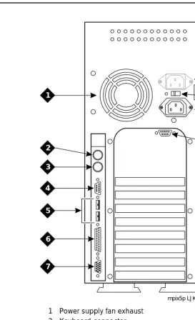
Figure 2-12. Back View of the MAP/5P and MAP/5PV3
6. Simultaneously compress the dress cover latches on both sides of the MAP/5P and MAP/5PV3 (Figure 2-13).
mpix5p LJK 072999 1
2 3 4
5
6
7
8 9
10
11
12
1 Power supply fan exhaust 2 Keyboard connector 3 Mouse connector (not used) 4 COM1
5 COM2 (MAP/5P) or USB ports (MAP/5PV3, not used) 6 Parallel port
7 Monitor connector
8 AC power supply outlet (MAP/5P only) 9 Dress cover lock
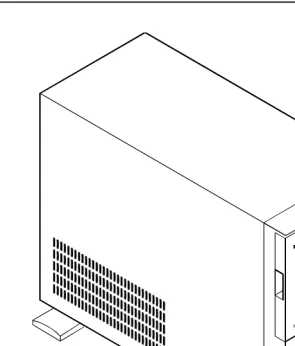
Figure 2-13. Removing the Dress Cover
7. Slide the dress cover away from the MAP/5P and MAP/5PV3.
8. Continue with ‘‘MAP/5P and MAP/5PV3: Install or Remove Circuit Cards’’.
MAP/5P and MAP/5PV3: Install or Remove
Circuit Cards
Install or remove circuit cards as needed. The final configuration for the MAP should be:
MAP/5P and MAP/5PV3: Remove the DCIU Circuit Card (GP Synch or EICON).
Use the following procedure to remove a DCIU circuit card (GP Synch or EICON) (Figure 2-14):
1. Locate the circuit card (Figure 2-14) to be replaced within the card cage.
Integration Configuration
DEFINITY CLAN The DEFINITY CLAN integration does not require a switch integration circuit card. It does, however, require a LAN circuit card installed into the lowest numbered, available ISA slot.
DEFINITY DCIU The DEFINITY DCIU integration requires a DCIU circuit card (GP Synch or EICON) installed into the lowest numbered, available ISA slot after the LAN circuit card, if present, has been installed.
MERLIN
LEGEND/MAGIXs Communications Systems
The MERLIN LEGEND/MAGIXs Communications Systems do not use a switch integration or LAN circuit card for the integration.
ProLogix/DEFINITY Mode Code
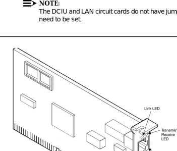
Figure 2-14. GP Synch and DCIU (EICON) Circuit Card Faceplates
2. Disconnect any attached cables.
3. If there are cables attached to other circuit cards which would impede the removal of the circuit card, disconnect them and place them to the side.
NOTE:
Pay close attention to the connectivity of each cable.
4. Remove the retaining screw from the circuit card faceplate and save it.
5. Remove the circuit card from the backplane slot by gently pulling on each corner of the circuit card.
6. Remove the circuit card from the MAP/5P or the MAP/5PV3.
7. Determine your next step:
■ If you are converting to a CLAN integration, continue with ‘‘MAP/5P
and MAP/5PV3: Install Circuit Cards’’.
■ If you are not converting the system to a CLAN integration, continue
with ‘‘MAP/5P and MAP/5PV3: Close the MAP’’ on page 2 2-35. RS-232C
25-pin connector
RS-232C 25-pin connector
LED (green) GP Synch
circuit card
DCIU (EICON) circuit card
MAP/5P and MAP/5PV3: Install Circuit Cards.
If you are converting the system to a CLAN or a DCIU integration, complete the following steps. The CLAN integration requires a LAN circuit card. The DCIU integration requires a DCIU circuit card (EICON).
NOTE:
The INTUITY system only uses one LAN or DCIU circuit card (EICON). Do not install two LAN or DCIU circuit cards into the system.
1. Unpack the new circuit card from its ESD protective wrapping.
■ Figure 2-14 shows the DCIU circuit card (EICON). ■ Figure 2-15 shows the LAN circuit card.
NOTE:
The DCIU and LAN circuit cards do not have jumpers or switches that need to be set.
2. Holding the circuit card by its corners, slide the card into one of the following positions:
■ For a DCIU circuit card (EICON), the lowest numbered, available
ISA slot after the LAN circuit card, if present, has been installed (Figure 2-16).
■ For a LAN circuit card, the lowest numbered, available ISA slot
(Figure 2-16).
3. Press the card firmly into the slot connector. The mounting bracket should seat completely so that the screw can be inserted easily.
NOTE:
With some circuit cards, the mounting bracket or faceplate will not fit perfectly when the card is fully seated in the connector. It may be necessary to adjust the faceplate.
Figure 2-16. MAP/5P and MAP/5PV3 Internal Layout
mpix5sid LJK 101298
PCI slot 1
PCI slot 2 PCI slot 3 ISA slot 2 ISA slot 3
ISA slot 4
ISA slot 5
ISA slot 6
4. Secure the circuit card faceplate into position by replacing the Phillips head retaining screw.
NOTE:
Do not connect the LAN cable at this time.Wait until instructed to do so.
5. Continue with ‘‘MAP/5P and MAP/5PV3: Close the MAP’’.
MAP/5P and MAP/5PV3: Close the MAP.
To close the map:
1. Align the dress cover with the MAP/5P and MAP/5PV3 chassis.
2. Slide the dress cover back until it locks into place.
3. Close the dress cover lock on the back of the MAP/5P and MAP/5PV3 chassis.
4. Reconnect any cords or lines that you removed from the system.
NOTE:
Do not connect the LAN cable at this time.Wait until instructed to do so.
5. Reconnect the monitor and the keyboard.
6. Reconnect the power cords.
7. Determine your next step:
■ If you removed the voice ports, continue with Task 19, "Connect the
Lucent INTUITY System to the Switch".
■ If you are installing CLAN or DCIU integration, continue with Task
19, "Connect the Lucent INTUITY System to the Switch".
■ If you are installing a mode-code integration and the ports are still
connected, continue with Task 20, "Apply Power to the System" on page 2-69.
MAP/40 Instructions
For additional information about the MAP/40, see INTUITY Messaging Solutions Release 4 MAP/40 Maintenance, 585-310-171.
MAP/40: Open the MAP
1. Turn off the power switch.
2. Remove the incoming AC power cord, keyboard, and video cord.
4. Remove the dress components.
a. Remove the top tape and floppy drive cover, if the system has one. Push up from the bottom of the cover, above the power switch (Figure 2-17, #1).
b. Remove the fan filter and cover. Press down on the top edge of the cover, below the power switch, to release it (Figure 2-17, #2). c. Pull off the bezel panel. The panel is attached by 2 fasteners at the
top and 2 at the bottom (Figure 2-17, #3).
d. Remove the screws holding the dress cover (Figure 2-17, #4).
l
Figure 2-17. Remove Front Covers and Bezel
5. Slide the dress cover forward and remove it (Figure 2-18, #5). princov1 LJK 042298
4
4
4
4
1
6. (Optional) Place the MAP/40 on its side to more easily work within the chassis. Use one of the following methods:
■ Place the MAP/40 on its side on a work table with the support base
over the table edge. You may need to disconnect incoming lines to do this. Label all disconnected lines.
■ If you cannot disconnect incoming lines to the MAP/40, place the
MAP/40 on its side on the floor and rest the end opposite the support base on large telephone books or similarly-sized objects to protect the support base.
7. Loosen the flat-head 1/4 inch screws holding the access cover by two turns only (Figure 2-18, upper left corner).
NOTE:
It is not necessary to remove these screws. They only need to be loosened to provide adequate clearance.
Figure 2-18. Remove the Dress Cover and Access Cover
10. Remove the circuit card retaining bracket. Locate and remove the two Phillips head screws that fasten the bracket to the chassis
(Figure 2-19, #7).
5 6
Figure 2-19. Remove the Retaining Bracket
11. Continue with ‘‘MAP/40: Install or Remove Circuit Cards’’.
princov5 LJK 042298
MAP/40: Install or Remove Circuit Cards
Install or remove circuit cards as needed. The final configuration for the MAP should be:
MAP/40: Remove the DCIU Circuit Card (GP Synch or EICON).
Use the following procedure to remove a DCIU circuit card (GP Synch or EICON) (Figure 2-20):
1. Locate the circuit card (Figure 2-20) to be replaced within the card cage.
Integration Configuration
DEFINITY CLAN The DEFINITY CLAN integration does not require a switch integration circuit card. It does, however, require a LAN circuit card installed in the highest available slot after both the multi-port serial and the DCIU circuit cards, if present, have been installed.
DEFINITY DCIU The DEFINITY DCIU integration requires a DCIU circuit card (EICON) installed in the highest available slot.
MERLIN
LEGEND/MAGIXs Communications Systems
The MERLIN LEGEND/MAGIXs Communications Systems do not use a switch integration or LAN circuit card for the integration.
ProLogix/DEFINIT Y Mode Code
Figure 2-20. DCIU Circuit Card (GP Synch or EICON) Faceplates
2. Disconnect any attached cables.
3. If there are cables attached to other circuit cards which would impede the removal of the circuit card, disconnect them and place them to the side.
NOTE:
Pay close attention to the connectivity of each cable.
4. Remove the retaining screw from the circuit card faceplate and save it.
5. Remove the circuit card from the backplane slot by gently pulling on each corner of the circuit card.
6. Remove the circuit card from the MAP/40.
7. Determine your next step:
■ If you are converting to a CLAN integration, continue with ‘‘MAP/40:
Install Circuit Cards’’.
■ If you are not converting the system to a CLAN integration, continue
with ‘‘MAP/40: Close the MAP’’ on page 2 2-43. RS-232C
25-pin connector
RS-232C 25-pin connector
LED (green) GP Synch
circuit card
DCIU (EICON) circuit card
MAP/40: Install Circuit Cards.
If you are converting the system to a CLAN or a DCIU integration, complete the following steps. The CLAN integration requires a LAN circuit card. The DCIU integration requires a DCIU circuit card (EICON).
NOTE:
The INTUITY system only uses one LAN or DCIU circuit card (EICON). Do not install two LAN or DCIU circuit cards.
1. Unpack the new circuit card from its ESD protective wrapping.
■ Figure 2-20 shows the DCIU circuit card (EICON). ■ Figure 2-21 shows the LAN circuit card.
NOTE:
The DCIU and LAN circuit cards do not have jumpers or switches that need to be set.
2. Holding the circuit card by its corners, slide the card into one of the following slot positions:
■ For a DCIU circuit card (EICON), the highest available slot.
■ For a LAN circuit card, the highest available slot after both the
multi-port serial and the DCIU circuit cards, if present, have been installed.
3. Press the card firmly into the slot connector. The mounting bracket should seat completely so that the screw can be inserted easily.
NOTE:
With some circuit cards, the mounting bracket or faceplate will not fit perfectly when the card is fully seated in the connector. It may be necessary to adjust the faceplate.
4. Secure the circuit card faceplate into position by replacing the Phillips head retaining screw.
NOTE:
Do not connect the LAN cable at this time.Wait until instructed to do so.
5. Continue with ‘‘MAP/40: Close the MAP’’.
MAP/40: Close the MAP.
To close the map:
1. Recheck all the cable dressing (routing) and connections.
2. Replace the circuit card retaining bracket (Figure 2-19). 3. Replace the circuit card access panel.
4. Replace the exterior dress cover.
5. Replace the front bezel:
a. Place the bezel frame onto the MAP. It should snap into place.
b. Replace the fan filter and cover. The narrow tab should be inserted in the bottom slot.
c. Replace the top tape and floppy drive cover, located at the top of the front panel, if the system has one. The narrow tab should be at the top.
6. Reconnect any lines that you have removed.
NOTE:
Do not connect the LAN cable at this time.Wait until instructed to do so.
8. Reconnect the power cords.
9. Determine your next step:
■ If you removed the voice ports, continue with Task 19, "Connect the
Lucent INTUITY System to the Switch".
■ If you are installing CLAN or DCIU integration, continue with Task
19, "Connect the Lucent INTUITY System to the Switch".
■ If you are installing a mode-code integration and the ports are still
connected, continue with Task 20, "Apply Power to the System" on page 2-69.
MAP/40P Instructions
For additional information about the MAP/40P, see Intuity Messaging Solutions Release 4 MAP/40P Maintenance, 585-310-197.
MAP/40P: Open the MAP
1. Turn off the power switch.
2. Remove the incoming AC power cord, keyboard, and video cord.
3. Tag the power cord plug with a note indicating that no one other than you should reconnect power to this equipment.
4. Set the MAP/40P tower upright on the support base.
Figure 2-22. Remove the front bezel and dress cover
6. Remove the six screws located along the bottom of the MAP/40P (Figure 2-22, #2).
There are three screws on each side of the MAP/40P.
7. Remove the screw holding the dress cover to the front of the MAP/40P Figure 2-22, #3)
8. Remove the screw holding the dress cover to the rear of the MAP/40P (Figure 2-22, #4).
9. At the rear of the MAP/40P, gently pull both sides of the dress cover away from the unit.
!
CAUTION:
Hold the dress cover out and away from the unit during removal to protect the circuit cards from damage.
INTUIT Y
h2in40p1 LJK 030900 44
5
5 6
2
2
2
2
2
2 3
1