COMPUTATIONAL ESTIMATION OF RISK OF HOT CRACKING
IN NARROW GAP WELDING
Heikki Keinänen1, Hannu Hänninen2, Teemu Sarikka2
1
VTT Technical Research Centre of Finland
2
Aalto University School of Engineering
ABSTRACT
The goal of this study was to computationally estimate the effect of geometry and boundary conditions on structural rigidity, stresses, strains and further on the possible risk for hot cracking in the case of narrow gap welding. Two different mock-ups were examined, the first was a plate mock-up and the second a nozzle mock-up.
The computation was performed utilising specifically tailored finite element analyses. The material non-linear characteristics were taken into account, and temperatures, deformations, stresses and strains were computed during and after welding.
Plate thickness was 50 mm and length 400 mm. The nozzle mock-up was a tubular specimen having inner diameter of 750 mm and wall thickness of 110 mm.
The materials of the plate mock-up were ferritic pressure vessel steel SA 508 with AISI 308L and 309L cladding and austenitic AISI 304 steel plate. The weld metal was Alloy 52. The materials, weld geometry and welding parameters of the nozzle mock-up were similar to the plate mock-up. In the case of plate mock-up cracking of the weld occurred in the first 7 weld passes. In the case of nozzle mock-up no cracking was observed.
The computed equivalent plastic strain at the middle of the weld in selected locations was compared to the critical strain for ductility dip cracking obtained from literature. The comparison shows that there is a higher risk for hot cracking in the case of the plate mock-up due to higher computed equivalent plastic strain. The risk of hot cracking decreases as the welding proceeds. The reason for the computed higher risk for hot cracking of the plate mock-up is most probably due to different structural rigidity and weld geometry/configuration of the plate mock-up in comparison to the nozzle model.
INTRODUCTION
The goal of this study was to computationally estimate the effect of geometry and boundary conditions on structural rigidity, stresses, strains and further on the possible risk for hot cracking in the case of narrow gap welding. Two different mock-ups were examined here, the first was a plate mock-up and the second a nozzle mock-up.
The computation was performed as follows:
! Specifically tailored finite element (Abaqus (2011)) analyses were utilised;
! The material non-linear characteristics were taken into account;
! Temperatures, deformations, stresses and strains were computed during and after welding.
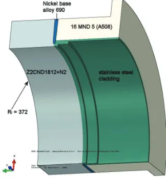
diameter of approximately 750 mm and wall thickness of approximately 110 mm, Figure 2. The flange-like part of the nozzle mock-up was only partly modelled as shown in Figure 2.
Figure 1. The plate mock-up. Plate thickness is approximately 50 mm.
Figure 2. The nozzle mock-up (one quarter of it). Only part of the flange like part was modelled as is shown.
MATERIALS, WELD GEOMETRIES AND WELDING PARAMETERS
The materials of the plate mock-up were ferritic steel SA 508 and austenitic steels AISI 304 (plate), AISI 308 and AISI 309 (cladding). The weld material was Alloy 52.
The welding parameters were selected similar to those used by manufacturers. Cracking of the weld occurred in the first 7 weld passes. After that no cracking was observed. Total shrinkage measured from the top of the groove was 2.5 mm after welding. The filling per weld bead was approximately 0.9–1.2 mm.
The materials, weld geometry and welding parameters of the nozzle mock-up were similar. The wall thickness was approximately twice that of the plate mock-up. The weld groove was slightly different. Initially there was also material under the first weld bead.
isotropic/kinematic hardening material model of Abaqus (2011). The combined isotropic/kinematic hardening material model was first introduced by Armstrong and Frederick (1966) and later expanded by Chaboche (1989). The combined isotropic/kinematic model is more suitable to cyclic loading conditions (as occurs in multi-pass welding) than the conventional kinematic hardening model.
The materials which were utilised in the analyses are:
! A508 (16 MND 5), ferritic material. Same properties were utilised for the both ferritic materials.
! Alloy 52 (Inconel 52), weld metal. Same properties were utilised for nickel base Alloy 690 in the
case of nozzle mock-up.
! AISI 304 (pipe and cladding). Same properties were used for AISI 309, AISI 308, Z2CND and
cladding materials.
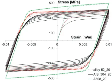
Figure 3 shows stress-strain curves for the materials at room temperature (constant strain amplitude 0.01).
Figure 3. Stress strain curves for the materials at room temperature (constant strain amplitude 0.01).
COMPUTATIONAL MODELS AND PROCEDURES
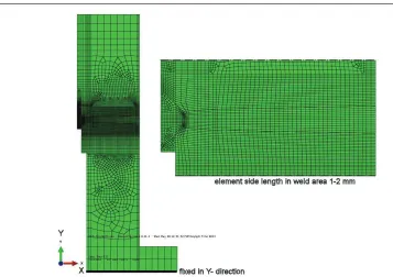
Abaqus 6.11-1 software (2011) was utilised in the analyses. Thermal and mechanical analyses were performed separately. In-house codes were used to generate some of the input data, see Figure 4.
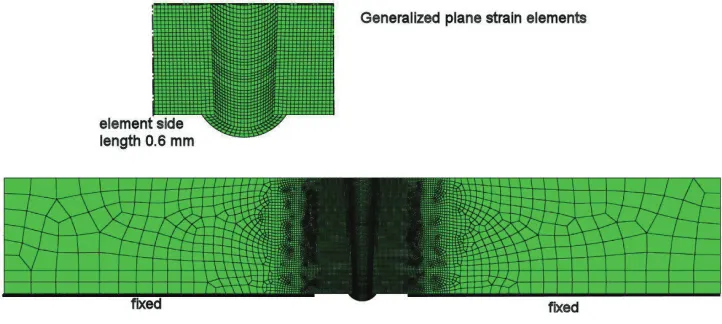
Second order (parabolic) reduced integration hybrid finite elements were used in order to avoid
volumetric locking1 (Abaqus axisymmetric element type CAX8RH and generalized plane strain element
type CPEG8RH). The generalised plane strain formulation involves a model that lies between two planes that can move with respect to each other and, hence, cause strain in the axial direction of the model. This formulation is considered to be necessary in the case of different materials and temperature change.
Small strains and displacements were assumed. The model of the plate mock-up is shown in Figure 5 and nozzle mock-up in Figure 6.
In the mechanical analysis, double elements (two sets of similar elements on top of each other) were used in the areas which were not yet active in the computation. The additional elements were modelled with remarkably low elastic modulus and material strength properties. Those elements were needed to track the accumulated deformation of the weld nodes, which are not yet active in the model. Otherwise the computed deformed shape would be highly distorted. Pass by pass modelling was performed adding the corresponding elements to the model (”model change, add”- option of Abaqus code).
In the thermal analysis the heat input was modelled using uniform internal heat generation and an exponential time function. The length of the time function was approximately chosen so, that the length of the heat input area was approximately 12 mm. In addition, the initial temperature of 1400 °C of the weld metal was modelled to simulate the initially molten weld metal and its heat content. The amount of the
heat inputQ [J/s]) was obtained using the welding parameters and thermal efficiency! as:
Q
# $
"
U I
$
, (1)whereU is voltage andI is current. The value of the thermal efficiency! of 80% was assumed. It was
selected in such a way that realistic size of the molten zone was obtained.
Figure 5. The plane strain finite element model of the plate mock-up. The thickness of the plate is 50 mm and width is 310 mm. Thus the whole width of the real plate was modelled.
1
Figure 6. The axisymmetric finite element model of the nozzle mock-up.
Concerning surface heat losses convection was modelled using heat transfer coefficient value of 100
W/m2K. The ambient temperature was 20 °C. No heat losses from weld pool were modelled. Radiation
was not modelled. An efficiency of 80% was assumed in the welding.
In the mechanical analysis, mixed hardening material model of Abaqus including both isotropic and kinematic hardening was utilised. An annealing temperature of 1400 °C was utilised. The annealing procedure simulates the relaxation of stresses and plastic strains due to material behaviour near or in the melting temperature. Physically, annealing is the process of heating a metal part to a high temperature to allow the microstructure to recrystallize, removing dislocations caused by cold working of the material. During the annealing procedure the analysis code Abaqus sets all appropriate state variables to zero (in this case stresses, back stresses, and plastic strains).
In the welding simulation the actual weld elements were added to the model in the stress free state having an initial temperature of 1400 °C. Temperatures were read from the thermal analysis results.
HOT CRACKING
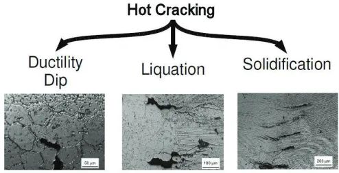
The mechanical cause of hot cracking is a combination of both a tensile strain and reduced material resistance to cracking (Nasser (2012)). In case of reduced material resistance deformation cannot compensate for a localized tensile strain. The reduced material resistance is only experienced within certain temperature ranges. There are different reasons for the reduction in material resistance and accordingly hot cracking can be classified (Figure 7) as follows (Nasser (2012)):
! Ductility dip cracking (DDC) in heat affected zone, hot cracking of HAZ. DDC occurs in a
completely solid phase e.g. for austenitic alloys DDC is observed approximately at half of the absolute solidus temperature.
! Liquation cracking (LC) in partially melted zone. Hot cracking occurs at the boundary between
liquation cracking. This type of cracking occurs in a solid-liquid coexistent region. Resistance to LC drops, because above the local solidus temperature the grain boundary melts, but the grain centre remains solid.
! Solidification cracking (SC) in fusion zone and hot cracking of fusion zone. Like liquation,
solidification cracking occurs in the solid-liquid coexistent region. Resistance drops because below local liquidus, dendrites growing in the completely liquid phase are surrounded by a liquid film.
The risk of hot crack nucleation can be predicted using the experimentally determined resistance. The prediction is based on a balance between resistance and driving force. The driving force is the strain increment in the susceptible temperature range.
Figure 8 shows experimentally determined critical strain for ductility dip cracking of Alloy 82 at different temperatures obtained from Chen and Hao (2010). In the same figure the experimentally determined critical strain for ductility dip cracking from Hänninen et al. (2006) for Alloy 82 and 52 is also shown. The weld materials of the mock-ups were Alloy 52 (plate mock-up) or Alloy 690 (nozzle mock-up). The critical strain shown for Alloy 52 in Figure 8 was utilised later.
Figure 7. The classification of hot cracking Nasser (2012).
RESULTS
Concerning thermal results, the maximum temperature at each node of the computation model was searched through the computation history to determine the computed molten pool. The computed circumferential residual stresses after welding at room temperature for the nozzle mock-up are presented in Figure 9. The computed transverse and longitudinal residual stresses after welding at room temperature for the plate mock-up are presented in Figure 10.
Figure 9. The computed circumferential residual stresses [MPa] for the nozzle mock-up after welding at room temperature. The axisymmetric results were swept to get three dimensional presentation (right).
Figure 10. The computed transverse (upper figure) and longitudinal residual stresses [MPa] for the plate mock-up after welding at room temperature.
Figure 11. The stresses along the lower surface (from left to right) at the end of the analysis after surface layer removal. S11 = transverse stress, S33 = longitudinal stress.
ASSESSMENT OF THE RISK OF HOT CRACKING
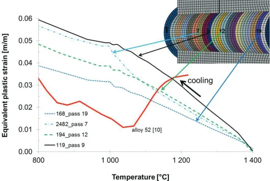
The risk of hot cracking was estimated in the same way as in Nasser (2012) and Chen and Hao (2010). In each location the computed equivalent plastic strain was plotted against temperature. This was performed only for one weld pass in the location of interest. The critical strain for ductility dip cracking (Figure 8) is plotted together with the computed results in Figure 12 and Figure 13. This critical strain curve was utilised for the both mock-ups due to lack of material specific data.
In the case of plate mock-up the computed strains exceed the critical strain curve. Thus hot cracking is considered to be possible. Although all the pass results were not examined, it is estimated, that the risk for hot cracking decreases approximately after the first 15 passes.
Figure 12. The computed equivalent plastic strain as function of temperature together with the critical strain for ductility dip cracking (Alloy 52 curve in Figure 8). Results are presented for four locations of
Figure 13. The computed equivalent plastic strain as function of temperature together with the critical strain for ductility dip cracking (Alloy 52 curve Figure 8). Results are presented for four locations of the
nozzle mock-up.
DISCUSSION
On the basis of the thermal results the size of the computed fusion zone was reasonable. The computed residual stresses of the plate mock-up include the effect of support beams and surface removal. The way of modelling those phases may affect the results, e.g. in which order the boundary conditions are released. This should be numerically studied in future.
The use of three dimensional models, although being much more time consuming, would give more detailed results. The utilised plane or axisymmetric models are simplifications of the real structure.
The utilised von Mises mixed hardening material model doesn’t include effect of microstructural behaviour, e.g. phase changes except in the values of the certain material parameters. Also the material model is developed for the lower temperature range. At higher temperatures the creep/relaxation and even material flow near or above melting temperature should be modelled, although this is usually not needed in the welding residual stress computations.
The critical strain curve for ductility dip cracking of weld metal Alloy 52 Hänninen et al. (2006) was utilised in the estimation of the risk of hot cracking. The actual critical strain curve for the present weld metal should be experimentally determined. The computation shows, however, that the strains in the weld centre of the plate mock-up are approximately twice larger than the strains of the nozzle mock-up.
The reason for the computed higher risk for hot cracking of the plate mock-up is most probably due to different structural rigidity and weld geometry/configuration of the plate mock-up in comparison to the nozzle model. The welded support beams in the case of the plate mock-up were required to limit the deformations during welding. In the case of the nozzle mock-up the structure itself is rigid enough.
SUMMARY AND CONCLUSIONS
The goal of this study was to computationally estimate the effect of geometry and boundary conditions on structural rigidity, stresses, strains and further on the possible risk for hot cracking in the case of narrow gap welding.
Two different mock-ups having a narrow gap weld were examined here, the first was a plate mock-up and the second a nozzle mock-up.
The computation was performed with Abaqus finite element code using a plane strain (plate mock-up) or an axisymmetric (nozzle mock-up) model. The non-linear characteristics of the material including temperature dependency and plasticity were taken into account.
The computed equivalent plastic strain at the middle of the weld in selected locations was compared to the critical strain for ductility dip cracking obtained from literature. The comparison shows that there is a higher risk for hot cracking in the case of the plate mock-up due to higher computed equivalent plastic strain. The risk of hot cracking decreases as the welding proceeds. Thus, the higher risk of hot cracking is also computationally predicted.
REFERENCES
Abaqus Theory Manual, version 6.11-1. (2011). Dassault Systemes.
International Weld Residual Stress Round Robin Problem Statement, Version 1.0, December 14, 2009. US Nuclear Regulatory Commission, Office of Nuclear Regulatory Research, Division of Engineering, Component Integrity Branch.
Crooker, P. and Rathbun, H. (2011). "Weld Residual Stress Finite Element Analysis Validation. Introduction and Overview", June 14-15, 2011, Rockville, MD, USA.
Zang, W., Gunnars, J., Dong, P. and Hong, J.K. (2009). "Improvement and validation of weld residual stress modelling procedure", SSM Research 2009:15. ISSN: 2000-0456.
Armstrong, P.J. and Frederick, C.O. (1966). "A mathematical representation of the multiaxial Bauschinger effect", C.E.G.B. Report RD/B/ N731, Berkeley Nuclear Laboratories, Berkeley, UK.
Chaboche, J. L. (1989). "Constitutive equations for cyclic plasticity and cyclic viscoplasticity",Int. J. of
Plasticity 5, 247–302.
Nasser, A. 2012. Computational Weld Mechanics Simulation of Hot Crack Nucleation. Ahmed Nasser
under the supervision of Prof. John Goldak. Carleton University.
http://www.weck.ca/MSS/ppts/16March2012.pdf
Cheng, C.M., Chou, C.P., Lee, I.K. and Kuo, I.C. (2006). "Susceptibility to Hot Cracking and Weldment
Heat Treatment of Haynes 230 Superalloy",J. Mater. Sci. Technol., (5):685–690.
Chen, J. and Hao, L. (2010). "Investigation on ductility dip cracking susceptibility of filler metal 82 in
welding",Transactions of JWRI, 39(2), p. 91–93.
![Figure 9. The computed circumferential residual stresses [MPa] for the nozzle mock-up after welding atroom temperature](https://thumb-us.123doks.com/thumbv2/123dok_us/1293932.1161941/7.612.194.415.193.373/figure-computed-circumferential-residual-stresses-nozzle-welding-temperature.webp)