GA26-1661-3
File No. 4300-07, 5/370-07
Systems
GA26-1661-3
File No. 4300-07, 5/370-07
IBM 3880
Fourth Edition, May 1980
This publication replaces and makes the IBM 3880 Storage Control Description, Order No. GA26-1661·2 and TNL GN26-0351. obsolete. Changes are indicated bya vertical line to the left of the change. Periodically, changes or additions may be made to the information in this manuaL Before using this p~blication in connection with the operation of IBM systems. consult your local IBM branch office for the editions that are current and applicable.
It is possible that this material may contain reference to, or information about. IBM products (machines and programs); programming or services that are not announced in your country. Such references or information must not be
construed to mean that IBM intends to announce such IBM products, programming, or services in your country.
Copies of this and other IBM publications can be obtained through IBM branch offices;
A form for reader comments is provided at the back of this publication. If the form has been removed. send your comments to the address below.
Preface
The IBM 3880 Storage Control and its attached disk storage devices provide high-speed, direct-access storage for general purpose data storage and system residence. It attaches to the processing unit through a block multiplexer channel.
For experienced programmers, this manual provides readily accessible reference material related to channel command words, sense bytes, and error recovery.
Less experienced programmers will fmd sufficient information to create channel programs to best use the standard and special features of the 3880.
This manual is organized by the following topics:
• Introduction - describes the basic units and lists highlights and functions.
• Input/Output Operations- describes operations between the processing unit, channel, and storage control.
• Fixed Block Command Set - describes each command in the fIXed block command set and gives examples of channel programs for reading and writing data.
• Count, Key, and Data Command Set - describes each command in the count, key, and data command set and gives examples of channel programs for formatting, reading, and writing.
• Standard and Special Features - describes all the features associated with the 3880 and gives examples of how they are used.
• Sense Bytes and Error Recovery Procedures - describes all sense bytes and error recovery procedures for each type of device that attaches to the 3880.
• Operator Panel - describes the switches and indicators associated with the operation of the 3880.
Programmers should be familiar with the information contained in the
IBM System/370 Principles of Operation,
Order No. GA22-7000, and theIBM 4300 Processors
Principles o[Operation,
Order No. GA22-7070.Additional information about the devices that attach to the 3880 can be found in the following manuals:
Manual Order Number
Reference Manual for IBM 3330
GA26-1615Series Disk Storage
Reference Manual for IBM 3340/3344
GA26-1619Disk Storage
Reference Manual for IBM 3350
GA26-1638Direct Access Storage
IBM 3370 Direct Access Storage
GA26-1657Description
Introduction to IBM
3375Direct
GA26-1666Access Storage
Introduction to IBM 3380 Disk
GA26-1662Storage
For definitions of terms used with direct access storage devices, see the
Data Processing Glossary,
Order No. GC20-1699.Contents
Introduction . . . Storage Directors. . Device Configurations
Features . . . .. . Two-Channel Switch Pair . . . . Two-Channel Switch Pair, Additional Eight-Channel Switch . . . . Remote Switch . . . . Speed Matching Buffer for 3380 Block Multiplexer
Command Retry . Record Overflow . End of File. . . .
Multitrack Operation . . . . 3330, 3333, and 3350 Attachment . 3340 and 3344 Attachment
3370 Attachment 3375 Attachment 3380 Attachment Input/Output Operations General Description. . Channel Operation . . Channel Address Word Channel Command Word Channel Status Word Program Status Word Status Presentation
Initial Status . . . Pending Status
-
,.,...-~ ..--Contingent Connection. Addressing. . . . Channel Commands. .
Control. Write. . . Read . . . Search . Sense Test I/O. Diagnostic
Fixed Block Command Set Transfer-in-Channel . No-Operation . Define Extent. Locate . . . Read . . . .
Read Initial Program Load Write. . . . Sense Input/Output. . . . Sense Input/Output Type . Read and Reset Buffered Log Read Device Characteristics . .
1-1
1-1
1-1
1-3 1-3 1-3 1-3 1-4 1-4 1-4 1-4 1-4 1-4 1-4 1-5 1-5 1-5 1-6 1-6 2-1 2-1 2-2 2-2 2-2 2-2 2-6 2-8 2-8 2-9 2-10 2-10 2-11 2-11 2-11 2-11 2-12 2-12 2-12 2-12 3-1 3-2 3-3 3-4 3-7 3-11 3-13 3-14 3-16 3-17 3-18 . 3-19Device Reserve Device Release Unconditional Reserve Diagnostic Control . Diagnostic Sense/Read Channel Programs
Write
Read . . . .
Count, Key, and Data Command Set No-Operation.
Recalibrate Seek . . . . Seek Cylinder . Seek Head. Space Count Set File Mask Set Sector . Restore. .
Transfer-in-Channel .
Search Home Address Equal . Search Identifier Equal. . Search Identifier High . . . Search Identifier Equal or High Search Key Equal . . . . Search Key High. . . . . Search Key Equal or High . Read Count
Read Record Zero Read Data. . . . Read Key and Data Read Count, Key, and Data
Read Multiple Count, Key, and Data Read Initial Program Load
Read Sector . . . .
Sense Input/Output Type. . . Sense Input/Output. . . Read and Reset Buffered Log Device Reserve
Unconditional Reserve Device Release Write Home Address Write Record Zero . . Erase . . . . . Write Count, Key, and Data Write Special Count, Key, and Data Write Data. . . .
Write Key and Data Diagnostic Sense .
4-48 Diagnostic Load . .
Diagnostic Write. . . Diagnostic Sense/Read. Channel Programs
. . 4-49
Track Formatting Update Write Read . . . Standard and Special Features Multitrack. . . . Record Overflow. . . . .
Formatting Overflow Records Processing Overflow Records . End of File. . . . Rotational Position Sensing Command Retry. . . . Channel Switching . . . Channel Selection Switch Device Status . " . . Remote Switching . . .
Statistical Usage and/or-Error Recording Error Detection and Logging .
Block Multiplexing . . . Error Recovery Procedures
Console Error Message .
Error Correction Function - Fixed Block Devices. . . . Restart CCWs - Fixed Block Devices . . Error Correction Function - Count, Key, and
Data Devices . . . . Restart CCWs - Count, Key, and Data
Devices. . . .
Command Retry - 3370 . . . . Internal Retry . . . . Command Retry - 3330 and 3350 .
4-50 4-51 4-51 4-54 4-56 5-1 · 5-1 · 5-2 · 5-2 5-3
5~4
5-5 · 5-8 5-8 5-8 5-9 5-9 5-9 5-9 5-9 6-1 6-1 · 6-1 6-2 · 6-3 · 6-6 6-7 · 6-7 · 6-8
Sense Bytes - 3370 . . 7-1
Sense Byte 0 . 7-1
Sense Byte 1 . 7-2
Sense Byte 2 . . 7-3
Sense Byte 3 . . . . . . 7-3
Sense Byte 4 . 7-3
Sense Byte 5 . 7-3
Sense Byte 6 . 7-3
Sense Byte 7 . . . . . . 7-4 Format 0 - Program or System Check . 7-4 Message Table - Format 0 . . . . . 7-4 Format 1 - Device Equipment Check . 7-5 Message Table - Format 1 . . . . . 7-8 Format 2 - Storage Director Equipment Check. 7-9 Message Table - Format 2 . . . 7-9
Format 3 - Storage Director Control Check (Hardware Detected) . . . . Message Table - Format 3 . . . . Format 3 - Storage Director Control Check'
(Microcode Detected) . . . . Message Table - Format 3 . . . . Format 4 - Data Checks Without Displacement
Information . . . . Message Table - Format 4 . . . . Format 5 - Data Checks With Displacement
Information . . . . Message Table - Format 5 . . . . . Format 6 - Usage Statistics/Overrun Errors . Message Table - Format 6
Error Condition Table - 3370 Recovery Action Table - 3370
7-10 · 7-10 7-11 7-11 7-12 7-12 · 7-13 7-13 7-14 · 7-14 7-15 7-16
Sense Bytes - 3330 . 8-1
Sense Byte 0 8-1
Sense Byte 1 8-2
Sense Byte 2 8-4
Sense Byte 3 8-4
Sense Byte 4 8-4
Sense Byte 5 8-4
Sense Byte 6 8-5
Sense Byte 7 8-5
Format 0 - Program or System Check . 8-6
Message Table - Format 0 . 8-7
Format 1 - Device Equipment Check. . 8-7 Message Table - Format 1 . . . . 8-9 Format 2 - Storage Director Equipment Check. 8-10 Message Table - Format 2 . . . 8-10 Format 3 - Storage Director Control Check
(Hardware Detected) . . . . Message Table - Format 3 . . . . Format 3 - Storage Director Control Check
(Microcode Detected) . . . . Message Table - Format 3. . . . Format 4 - Data Checks Without Displacement
Information . . . . Message Table - Format 4 . . . . Format 5 - Data Checks With Displacement
Information . . . . Message Table - Format 5 . . . . . Format 6 - Usage Statistics/Overrun Errors Message Table - Format 6
Error Condition Table - 3330 Recovery Action Table - 3330
Sense Bytes - 3350 . 9-1
Sense Byte 0 . 9-1
Sense Byte 1 . . . 9-2
Sense Byte 2 . . . 94
Sense Byte 3 . . . . . . . 9-4
Sense Byte 4 . . . . 9-4
Sense Byte 5 . 9-4
Sense Byte
,
6 . 9-5Sense Byte 7 . . 9-5
Format 0 - Program or System Check . 9';6 Message Table - Format 0 . . . . . 9-6 Format 1 - Device Equipment Check.. . 9-7 Message Table - Format 1 . . . . . 9-10 Format 2 - Storage Director Equ~pment Check. 9-11 Message Table - Format 2 . . . 9-11 Format 3 - Storage Director Control Check
(Hardware Detected) . . .. . . 9-12 Message Table - Format 3 . . . 9-12 Format 3 - Storage Director Control Check
(Microcode Detected) . . . 9-13 Message Table - Format 3 . . . 9-13 Format 4 - Data Checks Without Displacement
Information . . . 9-14 Message Table - Format 4 . . . 9-14 Format 5 - Data Checks With Displacement
Information . . . . . 9-15 Message Table - Format 5 . . . 9-15 Format 6 - Usage Statistics/Overrun Errors. . 9-16 MessageTable - Format 6 . . 9-16 Error Condition Table - 3330/3350 . . . 9-17 Recovery Action Table - 3330/3350 . . 9-18
Sense Bytes - 3340 and 3344 Sense Byte 0
Sense Byte 1 . Sense Byte 2 . Sense Byte 3 . Sense Byte 4 .
10-1 10-1 10-3 104 104 10-4 10-5 Sense Byte 5 .
Sense Byte 6 . Sense Byte 7 .
. . . . 10-5 10-6 10-7 Format 0 - Program or System Check
Message Table - Format 0 . . . . . Format 1 - Device Equipment Check. Message Table - Format 1 . . . .
. . 10-7 10-8 10-11 Format 2 - Storage Director Equipment Check. Message Table - Format 2 . . . . . Format 3 - Storage Director Control Check.
(Hardware Detected) . . . . Message Table - Format 3 . . . . Format 3 - Storage Director Control Check
(Microcode Detected) . . . . Message Table- Format 3 . . . • Format 4 - Data Checks Without Displacement
Information . . . . Message Table - Format 4 . . . . Format 5 - Data Checks With Displacement
Information . . . . Message Table - Format 5 . . . . Format 6 - Usage Statistics/Overrun Errors. . Message Table - Format 6 . . . .
Error Condition Table - 3340 and 3344. . Recovery Action Table - 3340 and 3344 Operator Panel
Subsystem Power System Configuration . Unit Emergency . .
10-12 10·12 10-13 10-13 10·14 10-14 10-15 10-15 to·16 10-16 10-17 10-17 10-18 10-19 10-24 10-24 10-24 10-24 Appendix - Device Addressing . . A-I
Introduction
Storage Directors
Device Configurations
The IBM 3880 Storage Control Models 1, 2, and 3 provide the logical capabilities to operate and control IBM disk storage devices. Each model of the 3880 provides different device attachment capabilities to satisfy the disk storage requirements for the following IBM systems and processors.
System/Processor Disk Storage
4341 3330/3333,3340/3344,3350,3370,3375
4331 Model Group 2 3330/3333,3340/3344,3350,3370,3375 System/370 Models 145, 145-3, 148, 3330/3333,3340/3344,3350
155-11, and 165-11
System/370 Models 158 and 168 3330/3333,3340/3344,3350,3380 3031,3032, 3033, and 3042 Model 2 3330/3333,3340/3344,3350,3375,3380
Disk storage attachment to each model of the 3880 is described in the Device Configurations section of this manuaL Depending on the type of disk storage attached, the 3880 attaches to the system through standard or high-speed, block-multiplexer channels.
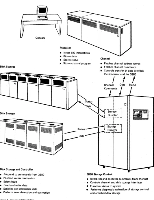
The 3880 contains two storage directors. Each storage director operates independently so that each one provides the basic functions for storage control. That is, each storage director has its own data path, control path, and address for channel communication (see Figure 1).
Through use of diskettes, each storage director can be initialized to attach the following types of disk storage devices: IBM 3340 and 3344; IBM 3330, 3333, and 3350; IBM 3370; IBM 3375; and IBM 3380.
The five disk storage options listed above are mutually exclusive on a storage director. For example, 3370s cannot be attached to a storage director initialized for 3340s and 3344s, and 3340s and 3344s cannot be attached to a storage director initialized for 3330,3333, and 3350 disk storage.
When a storage director is initialized to attach 3370 disk storage, it implements the com-mand set required for fixed block channel programs. The 3880 implements the count, key, and data command set for all other disk storage devices.
The following chart illustrates the various device configurations that may be attached to each model of the 3880.
Model Storage Director A Storage Director B
1 Up to 4 strings of 3330/3333/3350s Up to 4 strings of 3330/3333/3350s
or or
Up to 4 strings of 3340/3344s Up to 4 strings of 3340/3344s
or or
Up to 4 strings of 3370s Up to 4 strings of 3370s
or or
Up to 4 strings of 3375s Up to 4 strings of 3375s 2 Up to 4 strings of 3330/3333/3350s Up to 2 strings of 3380s
or
Up to 4 strings of 3340/3344s or
Up to 4 strings of 3370s or Up to 4 strings of 3375s
Disk Storage
Disk Storage
Disk Storage and Controller
• Respond to commands from 3880 • Position access mechanism • Select head
• Read and write data
• Serialize and deserialize data
• Perform error detection and correction
Figure 1. Functional Description
Processor
• Issues I/O instructions • Stores data
• Stores status Channel
• Stores channel program • Fetches channel address words
-• Fetches channel commands • Controls transfer of data between
the processor and the 3880
I t t
Channel Data Status
comr
ndSI /
3880 Storage Control
• Interprets and executes commands from channel • Controls channel and disk storage interfaces • Furnishes status to system
[image:9.626.26.560.39.732.2]Features
Two-Channel Switch Pair
Each storage director must be initialized for the desired device configuration, and is subject to the limitations described in the 3330, 3333, and 3350 Attachment, 3340 and 3344 Attachment, 3370 Attachment, 3375 Attachment, and 3380 Attachment sections of this manual. Storage directors that attach 3380s must either be attached to a 3-megabyte, block-multiplexer channel, which can operate in data streaming mode, or they must have the speed matching buffer feature for 3380s. Attachment of 3375s to the 3031, 3032, 3033, or 3042 Model 2 requires the data streaming feature on the processor.
Storage directors attaching 3350, 3370, or 3375 disk storage must be attached to either a 2- or 3-megabyte, block-multiplexer channel. Storage directors attaching 3330/3333 or 3340/3344 disk storage may be attached to either a 1-, 2-, or 3-megabyte, block-multi-plexer channel.
The 3880 is available with or supports the following standard and special features:
Feature 3330/3333/3350 3340/3344 3370 3375 3380
Two-Channel Switch Pair Yes Yes Yes Yes Yes
Two-Channel Switch Pair, Additional Yes Yes Yes Yes Yes
Eight-Channel Switch Yes No No No Yes
Remote Switch Yes Yes Yes Yes Yes
Speed Matching Buffer No No No No Yes
Block Multiplexer Yes Yes Yes Yes Yes
Command Retry Yes No Yes Yes Yes
Record Overflow Yes Yes No No No
End of File Yes Yes No Yes Yes
Mu Ititrack Operation Yes Yes No Yes Yes
A brief description of these features follows. For a detailed description see the Standard and Special Features section of this manual. In addition to these features the 3880 also supports the device features listed in the following sections of this manual:
• 3330, 3333, and 3350 Attachment • 3340 and 3344 Attachment • 3370 Attachment
• 3375 Attachment • 3380 Attachment
The two-channel switch pair feature provides logically separated switching facilities for both storage directors. It allows each storage director to be shared by two channels. The channels may be attached to the same processor or to different processors. Individual drives attached to a storage director may be reserved for the exclusive use of either of the channels.
Two-Channel Switch Pair, Additional
Eight-Channel Switch
The two-channel switch pair, additional feature is similar to a two-channel switch pair feature except that it enables four channels to share a storage director and its attached drives.
Remote Switch
The remote switch features remove the Enable/Disable switches from the 3880 operator panel and relocate them to a remote location. This allows an operator to reconfigure the system from a central point.
Speed Matching Buffer for 3380
Block MUltiplexer
Command Retry
Record Overflow
End of File
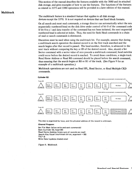
Multitrack Operation
The speed matching buffer feature allows 3380s to attach to block-multiplexer channels with a data rate less than 3 m~gabytes per second. The speed matching buffer can be installed in one storage director in a 3880 Model 2 or in either one or both storage directors in a 3880 Model 3. This feature is required to attach 3380s to System/370 Models 158 and 168 and to block multiplexer channels without data streaming on the 3031, 3032,3033, and 3042.
If , through use of a channel switch feature, a storage director is attached to a 3-megabyte channel and a slower channel, the speed matching buffer supports the 3-megabyte channel at a 3-megabyte data rate and the slower channel at a l.5-megabyte data rate.
The block multiplexer feature allows a storage director to disconnect from the channel during mechanical delays caused by commands that require repositioning of the access mechanism or excessive rotational delay.
Command retry is a channel/storage director procedure that allows a command in a channel program to be automatically retried. The retry does not cause an I/O interrupt and programmed error recovery procedures are not required.
Command retry is a standard feature on 3330, 3333, 3350, 3370, 3375, and 3380 devices; it is not used on 3340s and 3344s.
The record overflow feature allows a storage director to process logical records that exceed the capacity of a track. When using overflow records, the factor limiting the size of the record is the cylinder boundary.
Record overflow is a standard feature on 3330, 3333, 3340, 3344, and 3350 devices; it is not used on 3370s, 3375s, or 3380s.
An end-of-file record defines the end of a logical group of records. It is written by executing a Write Count, Key, and Data command with a data length of zero. Execution of the command by the storage director instructs a drive to write a data area consisting of one byte of zeros.
End of file is a standard feature for all devices except the 3370; it is not required on 3370s because of the fixed block format used with these devices.
On all search and most read commands, a storage director can automatically select the next sequentially numbered head on a drive. This eliminates the need for Seek Head commands in a chain of read or search commands.
3330, 3333, and 3350 Attachment
3340 and 3344 Attachment
3370 Attachment
When initialized for 3330, 3333, and 3350 operations, each storage director can attach up to four strings of 3330/3333 and/or 3350 disk storage. The first device on a 3330/3333 string must be a 3333 Modell or 11. Each 3333 may attach up to three 3330 Models 1, 2, or 11 in any combination.
The first device on a 3350 string must be a 3350 Model A2 or A2F. Each 3350 Model A2 or A2F may attach up to three 3350 Model B2s or B2Fs or up to two 3350 Model B2s or
B2Fs and one 3350 Model C2 orC2F. The 3350s must operate in native mode. Strings of 3330/3333s and 3350s may be intermixed on the same storage director. The 3880 supports the following 3330, 3333, and 3350 features:
• Rotational position sensing • String switch option • Remote switch
• 3350 fixed head option
• 3350 alternate controller feature
These features are described in the Reference Manual forlBM 3350 Direct Access Storage, Order No. GA26-1638, and in the Reference Manual for IBM 3330 Series Disk Storage, Order No. GA26-1615.
Each storage director, when initialized for 3340 and 3344 operation, can attach up to four strings of 3340s and 3344s. With the following limitations, the 3340s and 3344s may be intermixed on the same strings.
• On all strings, the first unit must be a 3340 Model A2.
• On strings 0 and 2, one, two or three 3340 Model B2s or 3344 Model B2s may attach in any order or combination. A 3340 Model Bl may replace one B2 at the end of the string. • On string 1, one, two, or three 3340 Model B2s may be attached. A 3340 Model B 1
may replace one B2 at the end of the string.
• On string 3, one 3340 Model B1 or B2 may be attached.
A maximum of 28 physical drives are allowed with a maximum of 64 logical device addresses.
The 3880 supports the following device features: • String switch option
• Remote switch
• Rotational position sensing • Fixed head option
These features are described in the Reference Manual for IBM 3340/3344 Disk Storage, Order No. GA26-1619.
When initialized for 3370 operation, each storage director can attach up to four strings (16 physical spindles or 32 logical device addresses) of 3370 Disk Storage devices. The first unit on a string must be a 3370 Model AI; up to three 3370 Model BIs may be attached to the Model AI.
The 3880 supports the 3370 string switch feature. This feature is described in IBM 3370
3375 Attachment
3380 Attachment
When initialized for 3375 operation, a storage director can attach up to four strings (32 logical device addresses) of 3375 disk storage. The first unit on a string must be a model A. Up to three additional model Bs may be attached to the first unit.
The 3880 supports the string switch feature that is available with the 3375. This feature is described in the Introduction to IBM 3375 Direct Access Storage, Order No. GA26-1666.
When initialized for 3380 operation, each storage director can attach up to two strings (32 logical device addresses) of 3380 disk storage. The first unit on a string must be a model A. Up to three additional model Bs may be attached to the first unit.
The 3880 supports the dynamic path selection function available with some models of 3380. Models with the dynamic path selection function may not be attached to a storage director with models not having the dynamic path selection function.
Input/Output Operations
General Description
Input/output (I/O) operations, initiated by I/O instructions in the system control program, are controlled by commands fetched from main storage by the channel. Arithmetic and logical operations are performed while the processing unit is in the problem state; for I/O operations, the processing unit must be in the supervisor state. The processing unit is changed from problem to supervisor state when a supervisor call instruction is executed or when an I/O interrupt occurs. The status of the system at the time of the change is stored in the program status word (PSW). See the Program Status Word section of this manual.
In the supervisor state, the processing unit can execute the following I/O instructions: • Start I/O -- Initiates an I/O operation if the addressed channel, storage director, and
disk drive are available.
• Start I/O Fast Release - Initiates an I/O operation if the addressed channel is available. The storage director and disk storage are assumed to be available. If not, an I/O interrupt occurs to indicate an unavailable condition.
• Halt I/O - Terminates the operation in progress at the channel and the storage director is disconnected from the channel.
• Halt Device - Terminates the operation in progress at the storage director without interfering with other I/O operations at the channel. This instruction should be used instead of Halt I/O to terminate an operation on a device attached to IBM block multiplexer channels.
• Test I/O - Sets the condition code in the program status word to indicate the status of the addressed channel, subchannel, storage director, and disk storage.
• Clear I/O - Discontinues the operation with the addressed device and stores the status of the discontinued operation in the channel status word (CSW).
After the specified instruction has been executed, the processing unit can return to the problem state and continue the interrupted program by reloading the program status word originally stored when the program entered the supervisor state.
Channel Operation
Channel Address Word
Channel Command Word
Channel Status Word
After successful execution of an I/O instruction, the channel independently selects and governs the storage director and drive addressed by the instruction. Reserved main storage locations contain information and instructions that enable the channel to perform those functions necessary to complete the operation.
Issuing a Start I/O or Start I/O Fast Release instruction causes the channel to fetch the channel address word from main storage location 72. Bits 0 through 3 of the channel address word (CAW) form the subchannel key for
all
commands associated with the I/O instruction. The subchannel key establishes the right of access (that is, whether data can be stored or fetched) to the particular main storage locations.The command address in bits 8 through 31 designates the address of the first channel command word. The three low-order bits of the command address must be zero to
specify the channel command word on doubleword boundaries.
Fetching of channel address words is a channel hardware function. The information must be set up in main storage location 72 before the processor issues the I/O instruction. The format and function of the channel address word are shown in Figure 3.
The channel fetches the first channel command word (CCW) from the address specified in the channel address word. The CCW specifies the operation to be performed, the main storage locations to be used, and the action to be taken when the operation is completed. The channel, if available when it receives the channel command word, attempts to select the device specified in the I/O instruction by sending the address to all attached control units. If the addressed device is attached to the channel and has power on, the command code portion of the channel command word is sent to the storage director, which responds with an initial status byte to the channel.
At this point, the Start I/O instruction is finished, releasing the processing unit to perform the next instruction. The results of the attempt to initiate execution of the command are indicated by the condition code in the program status word. If the I/O operation was not started, new status information containing the reason for this condition is ususally set in the channel status word. .
The format for the channel command word is shown in Figure 4.
The 'channel status word (CSW), stored at main storage location 64, informs the program of I/O device status or the conditions under which an I/O operation was terminated. The CSW is formed or changed during I/O interruptions and instruction execution. Status stored in the CSW remains unchanged until a subsequent interrupt occurs or a new I/O instruction is processed.
o
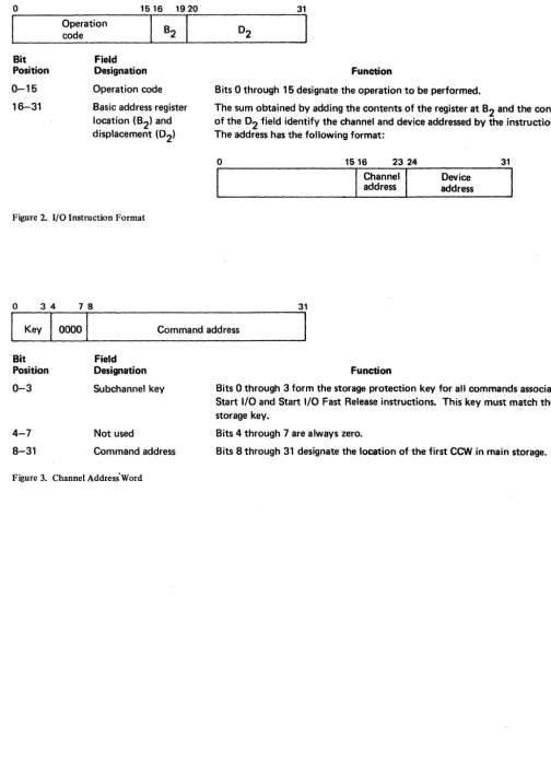
Bit Position 0-15 16-31
Operation code
Field
1516 1920
Designation Operation code Basic address register location (B2) and displacement (02)
Figure 2. I/O Instruction Format
o
34 7831
Function
Bits 0 through 15 designate the operation to be performed.
The sum obtained by adding the contents of the register at B2 and the contents of the 02 field identify the channel and device addressed by the instruction. The address has the following format:
o
31
1516 23 24
Channel
I
address address Device
31
I
KeyI
0000I
Command addressBit Field
Position Designation 0-3
4-7
8-31
Subchannel key
Not used
Command address
Figure 3. Channel Address'Word
Function
Bits 0 through 3 form the storage protection key for all commands associated with Start I/O and Start I/O Fast Release instructions. This key must match the storage key.
Bits 4 through 7 are always zero.
Bits 8 through 31 designate the location of the first CCW in main storage.
[image:16.629.57.561.52.748.2]o
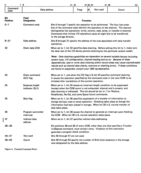
7 8 31 32 3739 40 47 48 63 Commandcode Data address Flags 00 Not used Count
Bit Position 0-7 8-31 32 33 34 35 36 37 38-39 40-47 48-63 Field Designation Command code Data address
Chain data (CD)
Chain command (CC) flag
Suppress length indicator (SLI) Skip flag Program controlled interrupt Indirect data address Not used Count
Figure 4. Channel Command Word
Function
Bits 0 through 7 specify the operation to be performed. The four low-order bits of the command code identify the operation to the channel. The channel distinguishes the operations: write, control, read, sense, or transfer-in-channel. Commands that initiate I/O operations cause all eight bits to be transferred to the storage director.
Bits 8 through 31 specify the address of the area associated with data transfer operations.
When set to 1, bit 32 specifies data chaining. Before setting this bit to 1, make sure the data rate of the I/O device permits chaining by the particular system model.
Note: Data chaining capabilities are dependent on several variable factors including system type, I/O configuration, channel loading and so on. Because of these
dependencies, read or write data chaining within record areas may cause unpredictable results such as channel data checks, overruns or chaining errors. If these conditions are found or suspected, consult your IBM representative.
When set to 1, and when the CD flag is 0, bit 33 specifies command chaining. It causes the operation specified by the command code in the next CCW to be initiated after completion of the current operation.
When set to 1, bit 34 causes an incorrect length condition to be suppressed (except when the CCW count is not exhausted, channel end is present, and data chaining is indicated). This bit should be set to 1 for Restore, Recalibrate, No-Op, and some Space Count commands.
When set to 1, bit 35 specifies suppression of a transfer of information to storage during a read or sense operation. Checking takes place as though the information had been placed in storage. When bit 35 is 0, riormal transfer of data takes place.
When set to 1, bit 36 causes the channel to generate an interrupt upon fetching the CCW. When bit 36 is 0, normal operation takes place.
When set to 1, bit 37 specifies indirect data addressing.
Bit positions 38 and 39 of every CCW, other than one that specifies a Transfer-in-Channel command, must contain zeros. Violation of this restriction generates a" program check condition.
Bits 40 through 47 are not used.
[image:17.631.3.570.39.736.2]o
31 32 3940. 4748Command address status Device Channel status Count
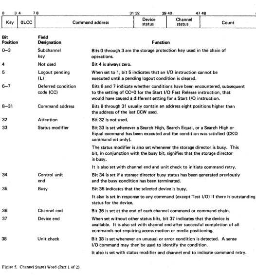
Bit Position 0-3 4 5 6-7 8-31 32 33 34 35 36 37 38 Field Designation Subchannel key Not used Logout pending (L) Deferred condition code (CC)
Command address Attention Status modifier
Control unit end
Busy
Channel end Device end
Unit check
Figure 5. Channel Status Word (Part 1 of 2)
Function
Bits 0 through 3 are the storage protection key used in the chain of operations.
Bit 4 is always zero.
When set to 1, bit 5 indicates that an I/O instruction cannot be executed until a pending logout condition is cleared.
Bits 6 and 7 indicate whether conditions have been encountered, subsequent to the setting of CC=O for the Start I/O Fast Release instruction, that would have caused a different setting for a Start I/O instruction. Bits 8 through 31 usually contain an address eight positions higher than the address of the last CCW used.
Bit 32 is not used.
Bit 33 is set whenever a Search High, Search Equal, or a Search High or Equal command has been executed and the condition was satisfied (CKD command set only).
The status modifier is also set whenever the storage director is busy. This bit, in conjunction with the busy bit, signifies that the storage director is· busy.
It is also set with channel end and unit check to initiate command retry. Bit 34 is set if a storage director busy status has been generated previously and the busy condition has been terminated.
Bit 35 indicates that the selected device is b~sy.
It also is set in response to any command (except Test I/O) if there is outstanding status for the device.
Bit 36 is set at the end of each channel command or command chain. When set without other status bits, bit 37 indicates that the device is available. It is also set with channel end after successful completion of all commands not requiring access motion or media positioning.
Bit 38 is set whenever an unusual or error condition is detected. A sense I/O command may then be used to identify the condition.
It also is set with status modifier and channel end to indicate command retry.
[image:18.627.62.589.62.627.2]o 34
Bit Position 39
40-47
48-63
78
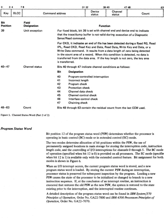
Field Designation Unit exception
Channel status
Count
31 32
Command address Device status
3940
Function
Channel status
4748
Count
For fixed block, bit 39 is set with channel end and device end to indicate that the trace/dump buffer is not valid during execution of a Diagnostic Sense/Read command.
For CKD, it indicates an end of.file has been detected during a F!ead RO, Read IPL, Read CKD, Read Key and Data, Read Data, Write Key and Data, or a Write Data command. It results from a data length of zero being detected in the count area of a record. When this condition is detected, no data is transferred from the data area. If the key length is not zero, the key area is transferred.
Bits 40 through 47 indicate channel conditions as follows: Bit Designation
40 Program-controlled interruption 41 Incorrect length
42 Program check 43 Protection check 44 Channel data check
45
Channel control check 46 I nterface control check 47 Chaining checkBits 48 through 63 contain the residual count from the last CCW used.
Figure 5. Channel Status Word (Part 2 of 2)
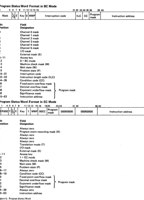
Program Status Word
Bit position 12 of the program status word (PSW) determines whether the processor is operating in basic control (BC) mode or in extended control (EC) mode.
The two modes determine allocation of bit positions within the PSW, the use of
permanently assigned locations in main storage for storing the interruption code, instruction length code, and the controlling of I/O interruptions for channels 0 through 5. The BC mode of operation (specified when bit 12 is 0) is provided on all processors. The EC mode (specified when bit 12 is 1) is available only with the extended control feature. Bit assignment for both modes is shown in Figure 6.
When an I/O interrupt occurs, the current program status word is stored, and a new program status word is loaded. By storing the current PSW during an interruption, processor status is preserved for subsequent inspection by the program. Loading a new PSW causes the state of the processor to be initialized or changed to branch to a new instruction sequence. If, at the conclusion of an interrupt routine, an instruction is executed that restores the old PSWas the new PSW, the system is restored to the state existing prior to the interruption, and the interrupted routine continues.
A detailed description of the program status word can be found in IBM System/370
Principles of Operation, Order No. GA22-7000 and IBM 4300 Processors Principles of
[image:19.626.26.563.41.755.2]Program Status Word Format in BC Mode
o
56781112131516 31 32 33 34 35 36I nterruption code
Bit Field
Position Designation
o
Channel 0 mask 1 Channel 1 mask 2 Channel 2 mask 3 Channel 3 mask 4 Channel 4 mask 5 Channel 5 mask6 I/O mask
7 External mask (E)
8-11 Access key
12 0
=
BC mode13 Machine check mask (M) 14 Wa it state (W)
15 Problem state (P) 16-31 Interruption code
32-33 I nstruction length code (I LC) 34-35 Condition code (CC)
37 Decimal overflow mask 38 Exponent underflow mask 36 Fixed-point overflow mask }
Program mask 39 Significance mask
40-63 I nstruction address
Program Status Word Format in EC Mode
Bit Position
o
1 2 3 4 5 6 7 8-11 12 13 14 15 16-17 18-19 20 21 Field Designation Always zeroProgram event recording mask (R) Always zero
Always zero Always zero
Translation mode (T) I/O mask
External mask (E) Access key 1 = EC mode
Machine check mask (M) Wait state (W)
Problem state (P) Always zero
31 32
00000000
22
Condition code (CC)
Fixed-point overflow mask } Decimal overflow mask
Progra m mask Exponent underflow mask
23 24-39 40-63
[image:20.629.73.577.42.739.2]Significance mask Always zero I nstruction address
Figure 6 .. Program Status Word
00000000
39 40 63
I nstruction address
63
Instruction address
Status Presentation
Initial Status
The initial status byte is zero for Test I/O instructions and all non-immediate commands unless one or more of the following conditions exists:
• Control unit busy is indicated for one of the following reasons:
1. A write operation is still in progress after chaining has been terminated. 2. The storage director is disconnected during command chaining when a storage
control error recovery procedure is in progress.
3. The storage director is performing a format defective block, check data, or format ID operation. (See the Channel Commands section for a description of the Locate, Write, or Diagnostic Control commands.)
4. The storage director is executing a diagnostic test.
5. A status condition is pending in the storage director for other than the addressed device. (See the Pending Status section of this manual.)
6. A system reset is in progress.
7. The storage director is maintaining a contingent connection to some device other than the addressed device. (See the Contingent Connection section of this manual.)
8. A storage director initiated connection is preferred over a channel initiated connection because presentation of consecutive device busy or zero status to the channel exceeds the number of devices that can be attached to the storage director.
9. The channel switch is busy.
• A status condition is pending in the storage director. (See the Pending Status section of this manual.) The pending status is presented as initial status and the busy bit is included in the status byte unless a Test I/O instruction was being executed. The busy bit indicates that the device is busy because of the outstanding status. The pending status is then cleared unless it is stacked by the channel. After the status is cleared, the device must be readdressed to determine whether it is available.
• The device is busy to the channel interface. In this case, the busy bit appears alone in the initial status byte. The device is busy to the interface if channel end occurred without device end for the device, and device end has not been generated, or if the device is reserved by another interface.
• A status condition is pending in the device. (See the Pending Status section of this manual.) The pending status is presented as initial status and the busy bit is included in the status byte unless a Test I/O instruction was being executed. The pending status is then cleared unless it is stacked by the channel.
• A unit check condition exists at the storage director or device. In this case, unit check is presented as initial status unless the command was one of the sense commands. A zero initial status byte is presented for the sense commands.
• Initial status indicates command retry. • Invalid parity is sensed in the command code.
Pending Status
A pending status condition can exist for either the storage director or a device. Status is pending for the storage director if:
• A Halt I/O or Halt Device instruction was signaled after a command was issued but before channel end status was accepted. The ending status for the operation is pending after the operation is complete.
• A Halt I/O or Halt Device instruction was signaled during a Test I/O instruction before the status was accepted by the channel. The status for the addressed device remains pending in the storage director.
• Busy, channel end, or unit check status was stacked by the channel.
• Zero status in response to a Test I/O instruction was stacked by the channel.
• Control unit busy status was presented to the channel. (Control unit end is pending.) • Device end status from a Locate or Diagnostic Control command is stacked.
Note: If device end status for a pack change interrupt is stacked in a multichannel environment, the status is pending in the storage director, but the storage director does not appear busy for all other devices.
Status pending for the storage director (except for control unit end) causes the storage director to appear busy for all devices except the device for which the status condition exists. Unless it is busy, the storage director will request service to clear the pending status. Status is cleared when presented to, and accepted by, the channel.
Status is pending for a device if: • Channel end was presented alone. • Busy status was presented.
• The device has gone from a not ready status to a ready status. • Device end status from a Seek or Set Sector command is stacked.
Status pending for a device causes the storage director to request service when both the storage director and device are not busy. The status is cleared when presented to, and accepted by, the channel.
Priority of Pending Status Conditions
When presented via polling, the priority of pending status conditions is: • Status pending in the storage control (except control unit end) • Unsuppressible status
• Suppressible device end status • Control unit end status
Note:
During a contingent connection, control unit end has first priority.
Address Associated with Pending StatusSuppressible Status
Contingent Connection
Addressing
All status conditions (except control unit end) are associated with a specific device address. When there is no contingent connection, control unit end may be cleared by addressing any of the devices attached to the storage director. However, during a contingent connection, control unit end is associated with the specific address for which the contingent connection is being maintained.
When presented via polling, the address associated with control unit end status is always that of a non-busy device within the range of addresses recognized by that storage director.
All status conditions are suppressible except (1) device end status associated with channel end for which chaining has been indicated and (2) the device end status associated with unchained Locate or Diagnostic Control commands. ,
A contingent connection is established in the storage director after the channel accepts a status. byte containing unit check. It lasts until a command other than Test I/O or No-Operation receives an initial status byte of zero for the storage director and device address that generated the unit check, or a selective or system reset occurs.
During the contingent connection state, the storage director is busy to all addresses other than the address for which the contingent connection state was established.
Each 'storage director and device is assigned an I/O address at the time of installation. This ~ddress (8 bits) is used by the program to select a particular device. The address is specified in bits 24 through 31 of the I/O instruction and has the following format: Bit Function
0-1 Storage director address
2-4 Storage director and controller address or controller address 5-7 Logical device address
Condition code 3 (not operational) is set in the PSW if an attempt is made to address a storage director, controller, or string that is non-existent, powered off, or disabled by the string switch feature.
If an addressed drive in a properly selected string or controller is non-existent or powered off, unit check is presented in the initial status.
Channel Commands
Control
Write
Read
The 3880 supports two different channel command sets: one for devices using a count, key, and data (CKD) format, and one for devices using a fixed block format. In most cases the command codes for each command set are different and cannot be used with the other command set.
There are six basic types of commands: control, write, read, search, sense, and diagnostic. Tl1e following is a brief description of the basic types of commands. Individual commands for each command set are described in detail in the Fixed Block Command Set and Count, Key, and Data Command Set sections of this manual.
Control commands do not involve a transfer of data records between the storage director and main storage. However, in many cases control information is transferred from main storage to the storage director. This information may include an order code specifying some further actiort to be taken by the storage director or device, or it may contain parameters defining the types of operations that are allowed or data areas which may be accessed.
The data address field of the channel command word designates the location containing the required additional information.
Write commands transfer data from main storage to disk storage. Data is fetched from main storage in an ascending order of addresses, starting with the address specified in the data address field of the channel command word.
Read commands transfer data from disk storage to main storage. Data is placed in main storage in an ascending order of addresses, starting with the address specified in the data address field of the channel command word.
Search
Sense
Test I/O
,Diagnostic
The search commands are part of the count, key, and data command set. During execution of search commands, the channel operates in write mode while the disk storage operates in read mode. The storage director compares the data coming from the drive against the data from main storage. When the search requirement has been satisfied (for example, compared equal, high, and so on), the storage director returns a status modifier bit with channel end and device end. This causes the channel to skip the next CCW in the chairt and fetch the next command from a storage location 16 positions higher than the current CCW. This is normally done by chaining a Transfer-in-Channel (TIC) command to the search command. The following is an example of this procedure: Search Key Equal
TIC*-8 Read Data
As long as the search is unsuccessful, the TIC command following the search command causes the search to be repeated. When the search is successful, the status modifier causes the TIC command to be skipped and the Read Data command to be executed.
The Sense I/O command transfers 24 bytes of information from the storage director to the channel. The Sense I/O Type command transfers seven bytes of information that define the DASD configuration. These 24 bytes provide information concerning unusual conditions detected in the last operation and the current status of the storage director and device.
Other sense type commands perform other functions (such as reserving a device) in addition to transferring the sense information.
The Test I/O command is not the result of the channel executing a CCW and it is not written into the channel program by the programmer.
The Test I/O command is automatically generated by the channel when the channel requires status information, or is the result of processing a Test I/O instruction. In either case, it appears to the storage director as a command byte of all zeros and is treated as an immediate command. Test I/O requests the storage director to send all outstanding status information to the channel. Test I/O normally presents an all-zero status byte. Stacked or pending status (if any) is presented in initial status.
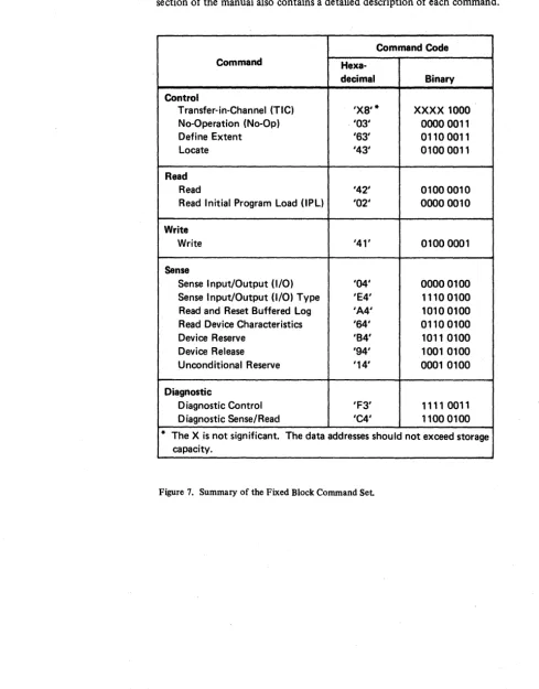
Fixed Block Command Set
Figure 7 is a summary of the fixed block command set used for 3370 operation. This section of the manual also contains a detailed description of each command.
Command Code
Command
Hexa-decimal Binary
Control
Transfer-in-Channel (TIC) 'X8'* XXXX 1000 No-Operation (No-Op) '03' 00000011
Define Extent '63' 01100011
Locate '43' 01000011
Read
Read '42' 01000010
Read Initial Program Load (lPL) '02' 00000010
Write
Write '41' 01000001
Sense
Sense Input/Output (I/O) '04' 00000100 Sense Input/Output (I/O) Type 'E4' 11100100 Read and· Reset Buffered Log 'A4' 10100100 Read Device Characteristics '64' 01100100
Device Reserve 'B4' 1011 0100
Device Release '94' 1001 0100
Unconditional Reserve '14' 0001 0100
Diagnostic
Diagnostic Control 'F3' 1111 0011 Diagnostic Sense/Read 'C4' 11000100 * The X is not significant. The data addresses should not exceed storage
capacity.
Figure 7. Summary of the Fixed Block Command Set.
[image:26.623.66.555.116.741.2]Transfer-in-Channel
o 78 31 32 37 3940 4748 63
Command Data Address Flags Not Used Count
Code (Decimal)
XXXX 1000 Specifies the main storage location of the Ignored 00 Ignored 'X8' next CCW.
Function
Chaining Requirements
Status;
Description
The Transfer-in-Channel (TIC) command provides chaining capabilities for CCWs not located in adjacent main storage locations.
The TIC command cannot be the first CCW designated by the channel address word. One TIC command cannot transfer directly to another TIC command.
No unit status is presented. The channel status portion of the CSW is stored if either of the special requirements is violated, or if the data address portion of the CCW does not specify an address on a double word boundary.
No-Operation
o
78 31 32 37 39 40 4748 63Command Data Address Flags Not Used Count
Code (Decimal)
00000011 Not checked for validity; should not exceed Used at the 00 Must be nonzero to avoid '03' addressing capacity
Function
Chaining Requirements
Status
Description
discretion of program check programmer
The No-Operation (No-Op) command is used to maintain channel connection during I/O operations.
None.
Channel end and device end are presented in initial status.
Define Extent
o
78 31 32 37 39 40 4748 63Command Data Address Flags l\Iot Used Count
Code (Decimal)
01100011 Specifies the main storage location of the Used at the 00 16 '63 ' first byte of parameters discretion of
Function
Chaining Requirements
Status
Description
programmer
The Define Extent command transfers 16 bytes of parameters from the channel to the storage director. The parameters define the size and location of a data extent.
The Define Extent command must not be preceded by another Define Extent command in the same chain.
Initial status is normally zero. Channel end and device end are presented after the parameters have been transferred and checked for validity. Invalid parameters cause the command to be terminated with channel end, device end, and unit check status.
The data extent area, defined by the parameters transferred to the storage director, establishes limits on the device within which subsequent chained commands are permitted to operate. The parameter list also contains an inhibit mask to determine which types of commands are permitted in the chain.
The format of the parameters transferred is:
Byte
o
I 2 and 3 4 through 7 8 through 11 12 through 15
Description Mask byte Must be zero Block size
Offset to first block of extent
Relative displacement, in the data set, to the first block of the extent
Relative displacement, in the data set, to the last block of the extent
Define Extent
o 7 8 31 32 37 39 40 4748 63
Command Data Address Flags Not Used Count
Code (Decimal)
01100011 Specifies the main storage location of the Used at the 00 16
'63' first byte of parameters discretion of
Description (Continued)
Byte 0
Byte 1
Bytes 2 and 3
programmer
This byte is the mask byte. It is used to inhibit or control certain operations in subsequent commands in the chain. The function of the bits is:
Bits
o
and 1 00 01 10 11 2 and 3 45
o
1
o
1
6 and 7
Function
Inhibits format write operations Inhibits all write operations Must not be used
Permits all write operations
Must be 00 or parameters are invalid
Data area
CE area. Used for maintenance purposes only
Inhibit diagnostic commands Permit diagnostic commands Must be 00 or parameters are invalid
This byte is not used, but it must be set to zero or the parameters are invalid.
Define Extent
o
78 31 32 37 3940 4748 63Command Data Address Flags Not Used Count
Code (Decimal)
01100011 Specifies the main storage location of the Used at the 00 16 '63' first byte of parameters discretion of
Description (Continued)
Bytes 4 through 7
. Bytes 8 through 11
Bytes 12 through ·15
programmer
These bytes define the offset, in blocks, from the beginning of the data set to the first block of the extent .
These bytes define the relative displacement, in blocks, from the beginning of the data set to the first blockof the extent.
These bytes define the relative displacement,in blocks, from the beginning of the data set to the last block of the extent.
Note: The storage director uses the offset parameters to determine if the extent of the
data set is within the limits of the addressed device. If the limit is exceeded, the Define Extent command parameters are invalid and the command is terminated with channel end, device end, and unit check status.
The following example illustrates the use of bytes 4 through 15 in the Define Extent command. This is a data set consisting of three extents recorded on two logical devices. For example, if bytes 4 through 15
=
:00 00 02 08 00 00 00 64 00 00 00 95.'Device 1
o 99 100
Extent 1 (E1) E2
Device 2
3991400 E1 4991 5191520 E2 5691
149
--,
, ,
--... ...
... >
In the example, the Define Extent command is used to specify the second extent area of the data set. The limits of the extent are defined by the two displacements relative to the beginning of the data set (blocks 10010 and 14910 ). The location of the extent on the device is specified by an offset from the beginning of the device (block 52010 ),
A subsequent Locate command would specify a particular block of data by using a
Locate
o
Command Code
01000011
1431
Function
78 31 32 37 39 40 4748 63
Data Address Flags Not Used Count
(Decimal)
Specifies the main storage location of the Used at the 00 8 first byte of parameters discretion of
programmer
The Locate command transfers eight bytes of parameters from the channel to the storage director. The parameters specify the location and amount of the data to be processed.
Chaining Requirements
Status
Description
Byte 0
The Locate command must be preceded by a Read IPL or Define Extent command in the same chain or the command is rejected with channel end, device end, and unit check status.
Initial status is normally zero. Channel end is presented after the parameters have been transferred and checked for validity. See the following description for conditions causing command termination and status associated with the termination.
The parameters transferred by this command have the following format: Byte
o
1 2 and 3 4 through 7
Description Operation byte AUxiliary byte
Number of blocks to be transferred
Relative displacement of the first data block in the data set
Byte 0 is the operation by teo It specifies the type of record orientation that is required, and the operation to be performed when the desired track position is reached. Byte 0 consists of two functional parts; bits 0 through 3 are modifier bits, and bits 4 through 7 define the operation code.
Locate
o
78 31 32 37 39 40 4748 63Command Data Address Flags Not Used Count
Code (Decimal)
01000011 Specifies the main storage location of Used at the 00 8
'43' first byte of parameters discretion of programmer
Description (Continued)
Operation Code Bits (4 through 7). These four bits define the following operations:
Bits 4-7 0100 0001 0101 0010 0110
Operation
Format defective block Write data
Write and check data Read replicated data Read
Any other combination of bit settings is invalid and will cause the command to terminate with device end and unit check status.
Data transfer between the channel and storage director associated with these operations does not occur during execution of the Locate command. Data transfer is initiated by a read or write CCW following the Locate command.
Format Defective Block (0100): This operation code causes the storage director to flag the block specified by bytes 4 through 7 as defective. The storage director assigns an alternate block and establishes the appropriate backward and forward pointers.
If the mask specified in the Define Extent command inhibits format write operations, or if the Write Inhibit switch on the device is in the read-only mode, the Locate command is terminated with device end and unit check status.
Upon receipt of the format defective-block operation code, the storage director initiates an access to the first alternate block on the same physical cylinder as the defective block. The storage director then scans for the first unused alternate block. If there is not enough space in the alternate area of the same physical cylinder, the storage director initiates an access to the alternate area of the nearest physical cylinder and continues scanning. This process is repeated until an unused alternate block is found, or until all alternate space on the device has been scanned. If all alternate space has been used, the storage director signals unit check and device end status.
If an unused alternate block is located, the storage director saves the alternate block pointer and initiates an access to the defective block specified in bytes 4 through 7 of the parameters, verifies correct orientation, and formats the block identification (ID) with the defective flag bit on and the appropriate block pointer.
Format defective block operates on a single block only. Future references to the defective block cause the storage control to access the assigned alternate block.
Locate
o
7 8 31 32 37 39 40 4748 63Command Data Add ress Flags Not Used Count
Code (Decimal)
01000011 Specifies the main storage location of the first Used at the 00 8
'43' byte of parameters discretion of
programmer
Description (Continued)
If the Locate command was preceded by a Diagnostic Control command with a subcommand of Displace ID, the storage director writes the block ID in its normal, displaced, or extended-displaced position according to the Displace ID subcommand. The storage director then performs a readback check on the block ID just written. If it is unreadable due to data errors, the operation is terminated with device end and unit check status.
If the Locate was not preceded by a Diagnostic Control command, the storage director writes the block ID in its normal position and performs a readback check on the block ID. It is is unreadable due to data errors, the storage director rewrites the block ID at a displaced position and performs another readback check. If the ID is still unreadable, the storage director re-writes the block ID at an extended-displaced position and performs another readback check. If the data is still unreadable, the operation is terminated with device end and unit check status. In either case (with or without a preceding Diagnostic Control command) if the readback check is successful, the storage director initiates an access to the alternate block, verifies proper orientation, formats the alternate block ID with the appropriate flag byte and backward pointer, and presents device end status.
Write Data (0001): This operation code prepares the storage director to write one or more blocks of data. The number of blocks to be written is specified in the block count
parameters of the Locate command (bytes 2 and 3). If the mask specified in the Define Extent command inhibits all write operations, or if the Write Inhibit switch on the device is in the read-only mode, the Locate command is terminated with device end and unit check status.
The write data operation establishes write orientation in the storage director for the addressed device.
Write data causes the storage control to initiate an access to the first block to be processed. The relative displacement of the first block specified by bytes 4 through 7 of the
parameters is converted to the appropriate physical values for the addressed device. When the access to the block is complete, the device presents device end status.
Write and Check Data (0101): The storage director performs the same functions as described for the write data operation code and, in addition, performs a read back check on the data just written.
Read Replicated Data (0010): This operation code prepares the storage director to read one or more blocks of data from a range of replicated data. The number of blocks to be read is specified in the block count parameters (bytes 2 and 3). This operation establishes read orientation in the storage director for the addressed device.
Locate
78 31 32 37 39 40 4748 63
Command Data Address Flags Not Used Count
Code .; (Decimal)
01000011 Specifies the main storage location of the Used at the 00 8
'43' first byte of parameters discretion of
...
Description (Continued)
Byte 1
Bytes 2 and 3
Bytes 4 through 7
programmer
Read Data (0110): This operation code prepares the storage director to read one or more
blocks of data. The number of blocks to be read is specified in the block count parameters (bytes 2 and 3).
Read data causes the storage director to initiate an access to the first block of data to be processed. The relative displacement of the first block specified by bytes 4 through 7 of the parameters is converted to the appropriate physical values for the addressed device. Device end is presented when the access is complete.
Byte 1 is the replication count. This byte is ignored if byte 0 specifies a format defective block. Byte 1 must be zero if byte 0 specifies read, write, or write and check data. When byte 0 specifies read replicated data (bits 4 through 7
=
0010), byte 1 specifies a range of blocks containing replicated data. The first block of this range is specified by the relative displacement in byte_s 4 through 7 of the parameters.The storage director orients to the beginning of a unit of replicated data to minimize rotational delay.
The block count (bytes 2 and 3 of the parameters) specifies the number of blocks in a unit of replicated data. For example, if the block count is two and this two-block unit is replicated five times, the replication count is ten.
If the replication count is less than the block count, or if the replication count is not a multiple of the block count, the Locate command is terminated with device end and unit check status.
If the replicated count equals the block count, the storage director converts the read replicated data operation to a read data operation.
Bytes 2 and 3 are the block count parameters. They specify the number of sequential blocks to be processed by the command immediately following the Locate command. These bytes must not be zero or the Locate command terminates with device end and unit check.
Bytes 4 through 7 specify the relative displacement, in blocks, from the beginning of the data set to the first block to be processed. The storage director compares the relative block displacement of the blocks to be processed against the logical extent limits established by the previously executed Define Extent command.
Read
o
78 31 32 39 39 40 4748 63Command Data Address Flags Not Used Count
Code (Decimal)
01000010 Specifies the main storage location where Used at the Specifies the number of '42' the first byte of data is to be transferred discretion of bytes to be read
programmer
Function
The Read command causes data to be transferred from a device to the channel.
Chaining Requirements
Status
Description
The Read command must be chained from a Locate command or the command is! rejected with channel end, device end, and unit check status.
Initial status is normally zero. Channel end and device end are presented after the data is transferred to the channel. See the following description for conditions causing command termination and status associated with the termination.
Upon receipt of the Read command, the storage director reads the block ID and verifies correct orientation.
Note: If a Read command is chained from a Locate command and the storage director
is not read oriented for this device, the Read command is terminated with channel end, device end, and unit check status. See the description of the Locate command for additional information regarding read orientation.
After verification of orientation, the following 512-byte data block is read and transferred to the channel. This process is repeated until the block count specified in the preceding Locate command or the byte count specified in the Read CCW reaches zero. If the CCW count is greater than the byte count derived from the block count specified in the Locate command, data transfer stops when the block count reaches zero. If the CCW count is less than the byte count derived from the block count specified in the Locate command, data transfer stops when the CCW count reaches zero.
If a command overrun occurs on a Read CCW, the storage director signals retry status (channel or device end with status modifier and unit check) and disconnects. After re-orientation to the block, the storage director reconnects and continues the operation. Command overrun may occur because of late channel reconnection on a record ready interrupt.
If a service overrun occurs while reading a block of data (other than the first block), the storage director terminates the operation with retry status. Unit check status is then posted on the retried Read CCW.
If the service overrun is in the first block, the storage director attempts recovery through the use of command retry. If retry is unsuccessful, the storage director terminates the command with channel end, device end, and unit check status.