SYSTEMS
MANUAL
FOR
704FORTRAN
AND 709
FORTRAN
April,
1960
Applied Programming Department
International Business Machines
Cor
poratior 590 Madison AvenueTABLE OF CONTENTS
CHAPTER I
I1
IIIIV
v
APPENDIX I
PREFATORY NOTE
m INTRODUCTION
.I SECTION ONE
-
SECTION ONE-PRIME-
$ECTION ONE-
DOUBLE -PRIME., SECTION TWO
.I SECTION THREE
-
SECT,ION FOUR.I SECTION FIVE
.
SECTIONS FIVE-PRIMEAND
PRE-SIX.
SECTION SIXa LIBRARIAN AND
LIBRARY
L MONITOR
T GENERAL DIAGNOSTIC
-
EDITORS (FORTRANAND DIAGNOSTIC)
.PREFATORY NOTE
This manual is an attempt to fulfill a long standing, much-pressed request. That is, a request for an over-all, comprehensive explan- ation of the workings of the entire Fortran System. This includes, in addition to the compiler proper, the monitor, the editor programs,
and other corollary routines. It should be noted at the outset, however,
that there a r e a number of difficulties involved in such a presentation.
W e want to take note of them immediately $ 0 that you can better apprec-
iate the form and organization of the manual that follows.
F i r s t and foremost, Fortran is a vaat, comprehensive system. This,
alone, provides its own 4ifficulties. It means that any description of i t s workings can not be subsumed under the directional efforts of a single individual who understands it all. One individual could not know all the details and subtleties comprising the insides of all the sections marked
off by the fourteen Roman numerals of this manual. We have chosen to
make the attempt to bring you many of the fine points of the system; this is done by having the "expert" on each of the sections do the writing for
that section. The price that must be paid for this approach is obvious :
a single style of presentation and a aingly oriented organization cannot easily be obtained.
A certain lack of uniformity of the level of generalization used in the
various descriptions results. We t r u s t this will be understood. In some cases this lack of uniformity results from the nature of the subject matter; in others, i t results from the difficultv described. we attemot to minimize this difficulty by having an introduction which discusses the main points of each of the sections on approximately the same level, and, in the case
of section two of the compiler, having a general level discussion then a de-
tailed description.
Certain redundancies, of course, must result. We do not apologize for
these redundancies; rather, we suspect you will find them of value. A s a
matter of fact, in a manual of this kind, repetition will prove useful, especially since each added treatment of a subject matter will present it
from a unique viewpoint. What we do apologize for here is not having more
full cross-referencing.
The descriptions a r e kept on a general level. We deliberately have avoided
making references to machine and tape locations. This is in line with our
regarding this treatment a s an explanation of the system from a logical
standpoint. In otherwords, we a r e presenting what i s permanent
--
orrelatively permanent
--
ignoring those things which a r e subject t o moment-be made t o the listings, of course, for supplementation along this line.
A further advantage of this i s that it means we can, in general, give simultaneous treatment to the 704 and 709 F o r t r a n systems. With re- spect to this, however, it should be noted that we orientate our discussion primarily t o the 709 system, making reference to the manner i n which the 704 crystem differs.
W e wish to remind you, at this point, that the F o r t r a n reference and operations manuals, particularly the latter, comprise useful supplements to the present discussion.
In
addition, an excellent paper on the compileris included i n the Proceedings of the Western Joint Computer Conference
CTION
1. The primitive elements of the F o r t r a n system a r e the master tape and appropriate editor deck. With these two a system tape is made. This i s then used in the operation of the system.
2. In both 704 Fortran and 709 F o r t r a n the system tape consists of four files. In 704 Fortran, the f i r s t two files a r e compiler files. In 709 Fortran, the f i r s t file is the monitor file and the second i s the compiler
file. In both the systems the third file i s the library subroutine file and
the fourth is the diagnostic file. When 709 F o r t r a n i s not being used in the monitor mode (i. e., a single compile only i s occurring) the f i r s t r e - cord only of the f i r s t file is used. This is the Card-Tape Simulator.
3. The system tape, itself, i s manipulated by the tape record caller
routine, 1-CS. This s i t s in lower core a l l during compilation and c a l l s
in the succeeding record from the system tape. The compiler records
a r e always called in in sequence. Once a system record has been called and execute d, it i s not called again. ' It should be noted that i n 704 Fortran
some of the records of the f i r s t file, comprising the compiler, a r e not executed until after the records of the second file, These a r e the records
comprising the second pass of the section
6
assembly program. Recordsof the compiler may be called in singly or in a string, consisting of two o r three records.
Each record has a control word telling whether control, after the record is
read in, is to go back to 1-CS or to the executive program record itself. If
control goes to 1-CS, i t means that another record i n the string is to be
read from the system tape and execution recommences. This control word,
incidentally, i s contained in the information of the Master Record Card, corresponding to it, in the Editor Deck (see X N ) .
4. What follows i s a brief over all survey of the F o r t r a n compiler proper. It will attempt to serve a s the coordinating unit for the separate detailed write-ups, covering each of the sections of Fortran, which follow. As mentioned in the prefatory note, the material will necessarily cross-cut
some of the material of the specific write-ups; it will, however, in most
cases, be at a different level of generality.
a. The six sections. As is now fairly well known, Fortran falls
naturally into six main divisions, which we call sections. These
sections a r e always executed sequentially. There is never a r e t u r n
t o one section once it has been relinquiehed to go on to its successor.
In addition to the six primary sections, there a r e four secondary
sections. These should, however, be considered a s nothing more
5', and pre-6.
F o r t r a n may conceptually be considered a s falling into two divisions: the f i r s t , comprised by sections 1, 2 , and 3; and the second, by sections 4, 5, and 6. This is because at the end of section 3, the entire object program i s essentially compiled. It i s , i n fact, compiled except for the fact that i t exists i n the C.
L
T. format and that i t has symbolic tags (reference t o index r e g i s t e r s ) instead of absolute tags. It is then the job of the remaining t h r e esections t o remedy these two features. Sections 4 and 5 handle the
task of inserting the absolute tag references for the symbolic tag references. This, of course, includes the obligation t o i n s e r t the necessary loading and saving index r e g i s t e r instructions. Section
6, then, places the instructions i n the C.
L
T. format into the properr elocatable binary format.
As for the f i r s t three sections, i t may be considered that the f i r s t
two of these do the entire task of source program analysis. This
task includes performing most of the instruction (C. I. T. ) compil-
ation. With reference to some of the instructions, however, sec-
tions 1 and 2 simply compile information, in tabular form, t o pass
on to section 3, which uses these a s the key t o i n s e r t the proper in-
structions. Because the analyses of sections 1 and 2 a r e independent,
the C. I. T t s compiled a r e kept in separate files, which must sub-
sequently be merged. Section 3, therefore, has the task of perform-
ing this m e r g e a s well a s the second m e r g e implied by the instruct- ion file which it, itself, creates. Both section 3 and the l a s t p a r t of section 5, because of their position at the end of n e c e s s a r y p r i m a r y analyses, perform certain optimizing tasks consisting mostly of r e - moving or inserting certain instructions.
It i s well t o note that the F o r t r a n compiler makes extensive use of
tables. These may be considered a s of two types: those which a r e
made up directly from the source program statements, and those which r e s u l t from further analysis. It is the former c l a s s of tables which a r e mostly included i n the reference manual l i s t of tables and their s i z e limitations. The l a t t e r c l a s s do, i n some cases, impose further s i z e limitations. Most tables a r e passed on from one section t o another; some, however, a r e created purely for use within a
section. The source program statements, once scanned, a r e placed i n tabular f o r m and the source program rrtatementa a r e not r e f e r r e d t o again,
With one exception, F o r t r a n m a y be considered a s a one p a s s system.
That is, it looks at the source program only once, and it makes a s c a n
of each statement once only. F r o m then on, references a r e to tables
only. The exception noted is i n section 1 of the 709 systems. In this
the executable statements.
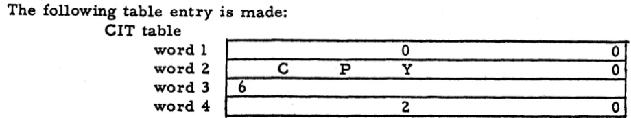
Among all the information placed in tabular form, i t would be well for the r e a d e r to keep i n mind the so-called C.
I.
T. table--
Com-piled Instruction Table. This becomes central for i t is, indeed,
the ultimate object of the compiler. Instructions, throughout the
system, until the section
6
assembly, a r e kept i n the four-word perentry table in buffers and r e c o r d s of 100 words (25 instructions).
This table i s illustrated. W e will m e r e l y note h e r e that word one con- tains the internal statement number, with an increment in the a d d r e s s
of the word, i f necessary; word two contains the mnemonic instruct-
ion code, with the address having the decrement value i f the code is
TXIs TXL, or TIX; word t h r e e has the symbolic address
(BCD)
; wordfour h a s the relative address (binary) with the a d d r e s s having f i r s t ,
the symbolic tag,
then,
the absolute tag.b. Section One. Section one has the p r i m a r y output of a file of in-
structions called the Compail file. In addition, it turns out a secondary f i l e of instructions, resulting from any Arithmetic Statement Functions
i n the problem. The Compail file consists of the following:
All
theinstructions resulting from a translation of the Arithmetic Statements. These arithmetic instructions, of course, r e f e r to symbolic tags in the word four address. Also included in this file a r e a partial translation
of the IF and GO TO Statements, the subprogram definition statements,
and the input/ output statements.
With respect to the
1,F
and GO TO Statements, section one compiles then e c e s s a r y t e s t instructions, but i t cannot compile the transfer instruct- ions. This i s because section one does not know whether any given IF and GO T O statement i s in the range of a DO and involves a t r a n s f e r out of the DO. It i s not until this is known that i t can be determined whether o r not any given transfer should be directly t o the statement indicated in the source program or t o a s e t of instructions providing necessary in- dexing, then the t r a n s f e r t o the specified source program state ment.
The analysis pertaining to these indexing instructions is left to section
two, with the physical instructions being compiled by a second p a r t of section three. In some c a s e s , a C. I. T. i s created containing the t r a n s - f e r instruction, but without the address. The a d d r e s s i s filled i n section three.
With respect to subprogram definition statements, information is gathered
which is used by section p r e - 6 i n actually filling i n the prologue and index- saving inst-ructions.
With respect to 110 statements, a l l instructions a m ompiled except
those involving
DO';
implied by 1/0 etatement l i s t s , After section onehas scanned and identified the source program statement, i t handles it
- A new internal formula number, incremented by one, i s assigned
to each input statement, whether that statement is executable o r
non-executable. Where external statement numbers
- -
i. e.,
state-ment numbers assigned by the source programmer
--
exist, theTEIFNO
table s e r v e s t o c o r r e l a t e the external and internal statement numbers.
The g r e a t e s t division in the handling of statements in section one is between the arithmetic statements and a l l others. The arithmetic com- piler proper constitutes the major portion of section one in number of instructions. The arithmetic compiler in making i t s scan of the arith- metic formula makes an enormous number of table entries in addition t o doing i t s statement analysis n e c e s s a r y for compilation. Among these
tables a r e the
TAU
tables, recording subscript combination inform-ation, the
FORVAL
and FORVAR tables recording fixed point variablesoccurring on the left and right hand sides of arithmetic statements, FIXCON and
FLOCON,
recording the converted fixed and floatingpoint numbers. It should be noted that the IF and
CALL
statementsfall onto both sides of this division. They a r e treated as arithmetic
statements, with compilation occurring that is not d u e directly t o the arithmetic compiler a s well.
The arithmetic compiler is divided into the Scan, Level Analysis,
various Optimizing routines, and the Compiler. The Level Analysis kifts out into one group a l l those algebraic operations which form a unit. A unit i s a group that must be performed together and have the s a m e o r d e r of binding strength for i t s operators. 'Plus'and h i n u s ' a r e one o r d e r of operators, multiplylandldivide' a r e another order. The l a t t e r has g r e a t e r binding strength than the f o r m e r ; consequently
when they occur i n the s a m e context the latter a r e assigned a higher level number. Needless to say, the use of parentheses in an arithmetic
statement is a p r i m e factor in determining units and, hence, level
numbers. Optimization occurs to minimize storage accesses. This
means that every attempt is made t o link one operation t o i t s s u c c e s s o r via the machine r e g i s t e r s r a t h e r than the storage cells. The com- pilation then proceeds from highest level number t o lowest.
c. Section One- r i m e . Section One-Prime is the longest of a l l the secondary sections. It has an enormous number of tasks t o p e r f o r m
involving sorting
,
combining, and moving of table information. Amongother things, using the
TEIFNO
table, i t substitutes internal formulanumbers for external formula numbers wherever these have had t o b e retained i n tables. This means that f r o m this point on, a l l F o r t r a n handling is i n t e r m s of i t s own assigned internal statement numbers. An example of where the external statement number has had t o be r e - tained till this point is in the TDO table. Here, the number r e f e r r i n g
t o the statement number of the DO itself m a y be an internal formula
number because i t is readily known due to the constant updating of the
designating the end of the DO range had t o be recorded a s an external
statement number at the time the TDO table entry was made. This
i s because i t could not then be known how many statements further on i n the program the end of the DO range occurred.
d. Section One Double-Prime. Section One Double- P r i m e is a diagnostic
section. It attempts t o find as many a s possible of the source program
e r r o r s that were not found by section one. E r r o r s pertaining t o the
syntax of any of the statements a r e detected by section one and noted in
section one's own diagnostic. Section One Double- P r i m e , then, finds as many as possible of the source program e r r o r 8 arieing f r o m a n
interrelationship of the statements. These, of course, pertain mainly
t o flow. Such things as a p a r t of the program that can't be reached o r a t r a n s f e r to a non-executable statement a r e found here. In general, then, i t is t r u e that by the end of one double-prime v e r y nearly a l l s o u r c e program e r r o r s have been found. Such things as over-lapping DO ranges and certain r a r e c a s e s of faulty flow still may not b e found until sections two and four or five. In addition, i t should be mentioned that t h e r e a r e a variety of table overflow e r r o r s which m a y be found a f t e r one double-prime. Most of the tables listed i n the Reference Manuals a r e , however, tested p r i o r t o this point and any overflow dis- covered. Both one-prime and one double-prime use the general diagnoutic of the fourth file, while erection one uses i t s own diagnostic.
e. Section Two. Section Two has for i t s p r i m a r y output a file of com- piled instructions called the Compdo file. In addition it, t 00, c r e a t e s
a secondary file, closed subroutines for the computation of relative
constant subscript combination load values. An additional important output a r e the TRALEV and TRASTO tables, which a r e essential for section t h r e e in producing the third file of F o r t r a n instructions, the
TIFGO
file.The Compdo file of instructions contains the computing and indexing instructions for the various subscript combinations contained within DO ranges and any necessary additional tags. These instructions a r e associated with the beginnings and ends of DO's. At the beginning of DO's they will contain the computing instructions n e c e s s a r y t o determine the load value for a tag (subscript combination index r e g i s t e r ) and the
load instructions. In addition, index saving instructions m a y occur.
At the end of DO's these instructions r e f e r t o the indexing required t o
increment subscript combination values for the next D 0 loop execution,
t o t e s t whether o r not control may pass out of the DO range and, i n thc l a t t e r c a s e , t o r e s e t the DO'S subscript combinations t o their lowest values if control is s t i l l in a DO containing the f i r s t DO. The instruct-
ions performing these three function8 a r e
TXI,
TXL, andT M ,
respect-ively.
within the DO-nest, on the other. A DO-nest i s defined as any s e t of
DO% all of which a r e bounded
--
contained within--
a single DO. Fig-uratively, this means that the outside single DO is on level one, the next
DO which it contains, on level two, and s o forth. Of course, in a
single nest there may be more than one DO on any one level greater
than level 1
.
(Please see IV for illustrations.
)Because this discussion of section two will be on
the
most general level,illustrations will not be provided. However, brief references to
the
structures of DO-nest in IV m a y prove useful. What we wish to do h e r e
i s present in general outline the origin of the problems that section two
must solve, which a r e explained in greater detail in IV.
Section two is a long section and much of its analysis complicated. A
great deal of this complexity ari,ses from the desire to provide an highly
optimized object program. In other words, some of the problems
could have been solved more simply, but at the cost of extra and in-
efficiently placed object instructions.
In any given DO-nest, section two attempts to place the subscript combina-
tion load value computation instructions a s far toward the outer DO of
the nest a s possible. Where these instructions cannot be placed with the
DO of level one, a search i s carefully made for the point of definition of all the parameters (nl
,
n2, n3) of the inner or higher level DO's.
These values a r e , of course, necessary for the DO computing instructions.
As soon a s they a r e found the next DO serves a s the base for the r e - quired instructions. This serves the purpose of avoiding the unnecessary
repetitions of the computing instructions if they were associated with the
inner DO's or the DOfls containing the subscript combinations to which
they r e f e r .
Another interesting way in which section two seeks maximum optim- ization is in i t s attempt to take advantage of the l k a r r y " condition
wherever possible. The k a r r y " condition may be described in this way. There a r e cases where the configuration of DO% and subscript combina- tions for a two or three dimensional a r r a y makes it possible to consider that a single one dimensional sweep over the a r r a y i s being made. In other words, the words a r e being referred to in core storage with the sequential references that a one dimensional a r r a y would have. Wherever conditions permit, section two t r e a t s such an a r r a y as if it w e r e , indeed,
single dimensional. The practical affect is to save on indexing instructions.
H e r e , a considerable, sophisticated analysis is required and it is under-
taken on the belief that gt eater object program efficiency makes it worthwhile.
Section two always uses a single tag (index register) for every subscript
combination, no matter how complex the subscript combination is. By
complexity we refer h e r e to number of subscript symbols and their associated
i t i s sometimes necessary to compile instructions, associated with the DO/ which provide proper reinitialization of the decrement value for the TXL instruction ending the DO on each successive pass through
the DO range. The SXDTX table i s used in this connection. It i s m a d e
up in section two and passed on to section three, part one. A config-
uration of indexing instructions is required for each possible config-
uration of subscript combinations
-
-
resulting from a permutation ofthe t h r e e possible subscript symbols. This means there a r e s i x possible blocks of such indexing instructions.
When a DO, LrX, i s within another DO, Y , and the
X
DO has been ex- ecuted i t s maximum number of times, there a r e two possible ways ofhandling the resetting of the X DO'S subscript combinations for the
next r e - e n t r y into the
X
DO. These, of course, must be r e s e t t o thevalue indicated by the n parameter of the
X
DO. They may be r e s e t4
a t the point of re-entry into the DO or at the point of departure from the DO. It is the l a t t e r course which F o r t r a n has chosen to take, This
accounts for the resetting TIX instruction following the TXL instruction
terminating the DO. This, in general, produces m o r e efficient object
programs, though it does c r e a t e the problem of handling."resettingl' where exit from the X (inner) DO occurs via a t r a n s f e r to a point in the
Y DO rather than through a normal termination of the X DO. T o handle
this problem, among others, i t i s necessary t o have a third file of in- structions, the TIFGO f i l e .
Whenever' a transfer is made from a DO to a point completely outside
its DO-nest, the values of all the indices of all the DO'S within whose
range the transfer instruction exists a r e saved. 'If, on- the other hand,
the t r a n s f e r goes to a point
-
-
really, a level--
outside the immediate DO but still within the DO-nest, section two makes a search to de- termine if it i s necessary t o save the index of the immediate DO o r DO'S from which the transfer occurred. This s e a r c h i s made by check-i a l l
FORVAR
entries existing on the level of the transfer point. Onesource of FORVAR table entries was.mentioned above; others a r e listed in II.
With respect to transfers, legal and illegal, section two does catch t r a n s f e r s f r o m within a DO into another DO. It does not, however, stop t r a n s f e r s from entirely outside a DO-nest into a DO. This is t o allow programmers t o take advantage of the feature enabling them t o t r a n s f e r out of a DO, execute a stretch of program, and r e t u r n t o the point of origin within the DO.
There a r e certain c a s e s where section two c r e a t e s a tag; that is, a tag
does not correspond t o a source program subscript combination. The
m o s t obvious case where this i s done is where a counter for a DO is
required. This i s where a DO on I does not have I appearing a s a
also created to handle the conditions described immediately above
--
where FORVARts a r e involved and the DO does not have i t s index symbol a s a tag anywhere in i t s range.But these instances a r e the simplest c a s e s of added tags: they r e f e r only t o a DO index. In other c a s e s , m o r e complicated tags, involv- ing two or t h r e e dimensioned subscript combinations, a r e created. Assume a DO on K within a DO on
J
within a DO on I, and the appear- ance of the subscript combination (I,J,
K, ) on level two; i. e.,
not i n the range of the DO on K, but i n the range of the other two DO's.Assume f u r t h e r that the value of
K
i n this subsctipt combination 1s s e t by a t r a n s f e r from within the DO on K t o a point in level two. In thiscase, i f the subscript combination (I,
J,
K, ) does not already existwithin the DO on K, one is created and placed there. This tag w i l l
then have the value needed a t the time of transfer. This situation accounts for another of the six types of
TRASTO
table e n t r i e s required t o inform section t h r e e of the TIFGO file instructions it m u s t cumpile.This l a s t c a s e a l s o help t o point up another important function of
section two: Tag Name Changes. Subscript combinations or tags are
given names which a r e nothing m o r e than the table entry recording
the information of the subscript combination. When section one m a k e s
up the ;elevant TAU table e n t r i e s i t does s o while examining each s t a t e -
ment separately, independent of i t s position within DO's. Therefore,
subscript combinations which syntactically look alike receive the s a m e TAU table entry and,consequently, the s a m e name. However, where subscript combinations receive their definitions and derive their load values independently of each other they a r e , for all p r a c t i c a l purposes,
different even though their syntactic appearance is identical. Section
two, t h e r e f o r e , m u s t s e e that *the names a r e changed t o a s s u r e independ- ent treatment of their indexing. F o r this purpose, a table called Un-
edited Change Tag Table is made up. Section t h r e e then physically
i n s e r t s the name changes.
A considerable portion of the work of section two i e devoted
t o tho p r o p c r handling of eubscript combinations which - are called r e -
-
lative constants. A relative constant is a subscript symbol not under control of a DO on that symbol. That is, i t receives i t s defintion i nsome fashion other than the indexing normally associated with a DO.
A subscript combination may, therefore, be a pure relative constant
(where none of i t s symbols is under control of a D O ) , a mixed=- lative constant ( w h e r e a t l e a s t one is not under control of a DO while the o t h e r s are), or a normal DO- subscript combination (where a l l
subscript symbols a r e under control of a DO). Each of t h e s e t h r e e types r e q u i r e s i t s own mode of treatment by section two. A b a s i c
point concerning handling of relative constants is that the computation
of the relative constant subscript combination load value i s done a t the point of definition of the relative constant r a t h e r than at the point of
use. This decision was m a d e p r i m a r i l y on the supposition that u s e s
-
point of definition, then, covers a variety of uses.
f'
F o r pure relative constants, there a r e two ways in which the com- putation appears at the point of definition. One i s simply by means
of the
LXD
instruction, loading from the relcon (relative constant)cell. This way applies only where the relative constant subscript
1 combination i s one dimensional and has no coefficient. The other i s
I
1 by means nf a transfer t o a closed subroutine, mentioned e a r l i e r ,
which computes the load value. This applies where the relevant sub- s c r i p t combination i s g r e a t e r than one dimension o r has a coefficient. Where relcons a r e of the mixed type, the closed subroutine f o r m will be used in some cases and, i n others, the computation will be associ- ated with the D W i n the usual way. The deciding factor here i s the level of definition of the relcon symbol. If the definition occurs within the s a m e DO-as the mixed relcon itself, the closed subroutine m u s t be used. In this case, in order to a s s u r e that the closed subroutine has a l l the subscript symbols available for computation, section two must s e e to i t that the DO subscript symbols of the mixed relcon a r e stored before the transfer i s made. Where the definition of the subscript symbol
is outside the DO, the computing instructions a r e associated with the
DOCof the next possible higher level DO.
*
The table
FORVAL
is the key in determining point of definition of r e - lative coastants. Causes of entries in this table were indicated above; others a r e described in 11. Every point of definition i s used a s the base for a relcon computation (of one of the two f o r m s described above). Section two cannot make the flow analysis necessary to eliminate super-fluous points. F o r example, where
I
i s a telcon and the problem con-tains two arithmetic statements in which I appears on the left side and
only one of them gets executed on the path of flow leading to the I relcon,
section two makes the computation instruction e n t r i e s at both points even though only one of them i s effectively valid.
W h e r e poosible, one of the subscript combinations appearing i n a DO is uaed
to
rervo ar the t e r t tag for the end of the DO; that i., it i. referred to by the terminatingTXL.
Where the DO index, itself, appears as o s e p a r a t e tag (whether because it i s a subscript in the source program or section two created one for i t ) , this tag is used to test the end of DO.In all othcr cases, section two attempts to determine the best tag for u s e
i n the end of DO test.
As a result of analyses like those mentioned above, and some others
that a r e indicated in the section two write-up, the
COMPDO
file i s madet o contain instructions giving highly efficient handling of DO loops.
with the .FIRSTESILE.
g. The program up to this point assumes an object machine with a s
many index r e g i s t e r s a s symbolic tags a r e used i n the section two in- structions. Since, however, the machine will have three index r e g i s t e r s , i t is necessary t o substitute assignments of these three for the indef- initely high number of symbolic tags. The object h e r e will be t o min-
imize the number of LXD1s and SXD's
- -
load and save instructions--
required by this fact. By %umber1' here, we mean'not only the number
of separate physical instructions, but also the number of executions of
them. That. is, optimization with respect to time takes precedence over optimization with respect to space. F o r example, if a tag is used i n a
v e r y high frequency part of the program (such a s the inner DO of a
DO-
nest three levels deep), and a branch transfer is made to four different a r e a s i , each of which requires saving of the tag b e f o r e i t is reused,
a single save instruction before transferring out of the high frequency a r e a is logically sufficient. However, our method is to place four
separate save i n ~ t r u c t i o n s a t the point of entry t o each of the four branch points, thus eliminating the instruction from the path which would r e - quire m o s t frequent executions of it.
This case a l s o s e r v e s t o illustrate some of the problems confronting
sections four and five
- -
the two sections whose concern this task is.It shows that there is a linkage, with-respect to index r e g i s t e r s , of different p a r t s of the program and that details of-the linkage must be knowin for efficient insertion of load and save instructions.
~ d r
example, i n the above case, the SXD will not be used on any of the four paths wherei t is not required. Furthermore, a comprehensive knowledge of a r e a s
and their expected frequencies of object time flow is necessary. As a
corollary t o these problems, t h e r e is the one of avoiding the SXD in- struction for a tag which i s no longer t o be used. That is, the tag can .
be efficiently
-
killed by over-loading i t i n i t s index register. T h e r e is a l s o the problem of knowing when t o save an index register when the next use of the tag i n i t requires a load instruction. If the l a s t reference to this tag is one that changed i t s value, it must be saved; i f the l a s t r e - ferences did not change i t s value but m e r e l y used i t s e a r l i e r established value, i t is not necessary t o save. Here, a distinction between active and passive references t o tags is necessary.This
entire complex of problems comprise the task of sections,$our and five. The work required of these sections falls naturally into twodivisions, allowing the division of labor between them. section four in- forms section five of the divisions of the object program for purposes of flow analysis and the relative frevquency of paths of flow over these divisions. Its task i s much the l e s s e r of the two sections. Section five then uses this information along with a knowledge of the specific tags required by each of the "divisions" t o assign absolute index r e g i s t e r s and compile neces s a r y indexing instructions.
it is well t o note how this work was presupposed i n the handling of symbolic index registers by the e'arlier sections of Fortran. Essent- ially, this can be stated very simply: the e a r l i e r sections simply ignored the problem and acted a s i f a s many index r e g i s t e r s a s were wanted were available. That i s , load instructions may appear in sequence up to
any number. The assumption i s the "savestt necessary to make the
"loadsH effective will be added later. The important thing t o note here is that SXDts and LXDts a r e not always coupled a s the previous discussion might imply. There i s an asymmetrybetween them; the e a r l i e r sections have complete freedom with respect to LXDts, very r a r e l y compiling an SXD. On the object program level this difference i s reflected in the cells which the SXD's and LXDts address. Section two's instructions, for example, mostly refer to the subscript symbol cells i n the regular data a r e a of core storage. On the other hand, section five's ins-tructions always r e f e r to the specially designated erasable a r e a for storage of index r e g i s t e r s . These erasable storage cells a r e r e f e r r e d to a s the
C) cells. The actual designation i s C)i, where i i s an increment result-
ing f r o m the conversion of the symbolic tag name. By means of this device t h e r e i s co-ordination between section five references to such tag storage cells and whatever section two references a r e necessary.
h. Section four has for i t s main task the assembling of four different
tables. These a r e the BBB table, the Predecessor, the Successor table, and the Tag List table. The p r i m a r y input to section four is the single file of merged C. I. T. Is; section four also uses other tables created earlier. The BBB table i s a l i s t of the Basic Blocks of the object pro- gram, plus indices referring to each Basic Bloc& Successors and
P r e d e c e s s o r s . A Basic Block i s the primary unit that section four works with
--
i t was referred t o by the word "divisiontt i n g. above. A BasicBlock is a stretch of program into which there i s only one entrance and
f r o m which there i s only one exit. wExit'' must here be interpreted i n the logical sense; that i s , i t may consist of m o r e than one transfer in-
struction, going to a variety of Basic Blocks. Each of these Basic Blocks, then, i s a Successor Basic Block. As implied by this, section
four m u s t m a r k off the Basic Blocks of the program and determine the
Successor and Predecessor Basic Blocks for any one Basic Block. A
BBB
entry corresponds t o each Basic Block; i t has references to theP r e d e c e s s o r and Successor tables denoting i t s P r e d e c e s s o r and Successor Basic Blocks. But section four's work goes beyond this. It must pro- vide the information to section five concerning frequency of paths of flow.
Therefore, the form of the Predecessor and Successor table entries which section four passes on to section five will contain, in addition t o the Basic Block reference number, a number denoting relative f r e - quency of transition between the two Basic Blocks. Here, the two Basic Blocks r e f e r to the BBB Basic Block and the Basic Block or Blocks of the P r e d e c e s s o r and Successor table that it designates. In order to achieve
these relative frequency numbers, section four performs a simulated
The major problem h e r e is in determining which Successor Basic Block to go to when, a s a result of a conditional transfer, a possibility of m o r e than one Successor Basic Block exists. At this point a "Monte Carloll technique' i s used. A random number i s generated and, i n
accordance with the numeric possibilities of succession indicated by the
frequency statement entries for that conditional transfer, a particular Successor Basic Block i s chosen. The random p u h b e r i s meant t o a s s u r e that over the long run of the entire simulated flow, the possible Successors will be .chosen in the proportions indicated by the Frequency entries. Where no Frequency entry i s made by the source programmer, the assumption i s that of equal probability for all paths of succession.
Some of the special problems encountered during the performing of this simulated flow a r e those given by conditional t r a n s f e r s where the con- ditions a r e s e t directly i n the source program (such a s
ASSIGN
GO T o ' s and Sense /Light Tests) and DO's involving variable parameters. F o r both of these additional intermediate tables a r e necessary. In the .caseof DO-nests, three general c i r curnstances, involving flow analysis problems, may occur. One i s a DO-nest whose DO'S all have constant p a r a m e t e r s and contain no transfers, another i s constant p a r a m e t e r s with transfers, and the third i s a DO-nest at l e a s t one of whose DO's has variable parameters. For the l a s t mentioned circumstance, either the frequency entry for the DO must be used or barring that, a frequency of five i s posited for the number of times oferepetition of the DO range.
F o r purposes of the simulated flow, a large number i s chosen, which i s
a function of the number of; Basic Blocks and distinct transfer' branches
occurring in the problem. . F o r every transition between a Basic Block
and i t s Successor that i s made during the simulation, this number is
ticked off by one. The flow ends when this number equals zero.
It should be pointed out, finally, that this simulated flow has nothing
whatever to do with the individual instructions of the problem. It is
concerned only with Basic Blocks a s units and not with the contents of a Basic Block. As f a r a s section four i s concerned a Basic Block m a y actually contain one hundred instructions or two instructions, and these instructions may contain many tags or no tags: section four's t r e a t - ment of i t i s the same. It may also be mentioned h e r e that the division
into Basic Blocks is based on an examination of the compiled instruct-
ions. Of course, the recognition of transfers
- -
beginning with theletter I1T"
--
i s vital. For this reason, section one finds it necessary t o use pseudo-names in the C. I. T. ' s of some of i t s instructions. It does not wish section four t o think that these end Basic Blocks when actually they do not.After the flow analysis i s completed, section four assembles the BBB, P r e d e c e s s o r , and Successor tables. These a r e a summary of the Basic
Block flow and relative frequency of this flow. The
BBB
entries a l s ol a s t significant item that each BBB entry contains i s an index t o the Tag List entries belonging to it. The Tag List table is made up a t the end of section four; i t is a l i s t of ail symbolic tags contained in the
C.
I. T. 's of the program togethei with a code designating the type of instruction referring to the tag. The index to this table that is placed i n the BBB entry, then tells which tags occur i n each Basic Block of the program and how they a r e used.i. Section Five m u s t now substitute references to tags 1 , 2 , and 4 for the symbolic tags which occupy the a d d r e s s portion of word 4 of the C. I. T. '8. A8 a corollary t o this, the loading and aaving instruction.
would be inserted for the appropriate index registers. These will load
from and lrave in the group of cells designated as C)--cells. The in-
formation contained i n the four tables created for i t by ~ e c t i o n four a r e sufficient to do thicr.
To perform this main task, section five operations fall logically into two
broad divisions. These are Region Generation and LXD and SXD Assign-
ment.
Region Generation i s the method of setting aside a portion of the p r o g r a m . consisting of one o r m o r e basic block^, for independent treatment with respect to index register assignment. After a s e t of basic blocks have been s e t aside a s a region and treated, i t then, a s a region, becomes a separate unit liable to be incorporated i n a new region along with other basic blocks. The flow configuration of a problem determines when a region itself becomes part of another region. When it does i t losee i t s
identity for the new region is an independent and separate unit. Ultimate-
ly, of course, all regions and basic blocks become absorbed into a single
region which i s the entire program. At this point the section five analysis
i s complete.
In
referring to "treatment" above, we mean the LXD andSXD
Aesignment.There is, then, an interweaving of the operations of the two main divisions
of section five, Region Generation and SXD and
LXD-
Assignment. (Thesecond of these divisions i s often r e f e r r e d t o as the LXing P a s s . ) The regions grow recursively until the entire problem i s one region. At any given time during this recursive treatment, several regions may exist independently or one only may exist.
P r i o r i t y i s given the high frequency path of flow in index r e g i s t e r assign- ment by the manner i n which regions a r e generated. Basic blocks a r e traced forward and backwards in flow, via the P r e d e c e s s o r and Successor
Tables, and those basic blocks a r e used f i r s t whose numeric linkages are
highest with other basic blocks, a s indicated in the figure on comparative frequency of paths of flow given by section four. When a region has been treated, if a l l three index r e g i s t e r s a r e assigned to the tags of that
region, i t is considered to be an opaque region. The tracing of basic
either a) there a r e no m o r e untreated linkages, b) a n opaque
region i s encountered, c) a loop is formed. The c ) case occurs
where the Predecessor o r Successor basic block i s one already i n the string. In this case, a l l basic blocks not within the scope of the loop a r e cut off. Where a region encountered during this t r a c e is a transparent region, as distinct from an opaque region, the t r a c e continues by way of the highest frequency untreated l i n k from i t o r into it, depending upon which direction the t r a c e is taking. Because, by definition, all the index r e g i s t e r s of a transparent region have not been used, i t i s subject t o further treatment and, consequently, may
be absorbed into the region a s a basic block is.
The "treatment" of a region is based on another type of simulated flow through it. This simulated flow affects the symbolic index r e g i s t e r
usage occurring i n the region. In cells representing the three index
r e g i s t e r s , the symbolic tags a r e loaded, then comparisons made with
successive symbolic tags, as these a r e revealed in Tag list. When
i t becomes necessary to save one of the t h r e e index r e g i s t e r s , a look ahead through Tag l i s t is made t o determine which i t is preferable t o save ; that is, which is l a s t used further ahead i n the program. It should be noted that two fundamental problems a r e involved here. One i s simply the problem of assignment of index r e g i s t e r s ; this involves . t h e compilation of LXD1s and the choice of a n index register. The
other is the problem determining when to save a n index r e g i s t e r when
the quantity is subsequently going to be over-written by a load into
that index register.
With respect t o the second of these two problems, a tag must be
saved t o initialize the appropriate C) cell for l a t e r loading, and t o handle "active" index r e g i s t e r s . "Activity" is denoted by the type of reference made to the tag i n the tag instruction. The Tag List code r e f e r r i n g to the tagged instruction tells essentially whether that
instruction is active o r passive. An active instruction i s simply one
that changes the value of an index register (such a s TXI or LXD) and
a passive instruction is one that uses the tag only ( such as CLA).
Where 'tactivitylt is present and a subsequent load will over-write the
index register, an
SXD
is inserted following the l a s t use of thesymbolic tag. Adtivity has meaning applying beyond the context of the
immediate region i n which i t is discovered. It may subsequently be
found that a pass on the flow f r o m this region r e q u i r e s the new tag value. Activity for regions, then, must be carefully noted.
As a result of this simulation within a region, the index r e g i s t e r s upon entry into a region and upon exit f r o m i t a r e assigned c e r t a i n
symbolic tags. These a r e noted in the
BBB
entry for the basic blocka s i t s entrance and exit conditions. When a region
--
which, of course,has been previously treated
--
ia encountered a match must be madeof the exit conditions of the l a s t basic block with the entrance con-
ditions of the basic block by which they region is entered. Where
treated region takes place to force compliance. If a match cannot be made, LXD1s a r e called for a t the head of the region. These LXD's a r e called inter-block LXDts because they concern the link- age between regions a s distinct f r o m basic blocks. There a r e a l s o
inter -block SXD1s. These r e s u l t from activity within a region already
treated. The SXD is placed a t the head of the region using the active tag. In this way, incidentally, the deployment of save instructions among different low frequencies paths raother than the single save instruction within the high frequency path occurs. This was r e f e r r e d to i n g.above.
Continuing to work i n this way, f r o m region to region, the high frequency paths of flow naturally receive priority i n the assignment
of index registers. . T h e SXDts and
LXD's
a r e inserted enforcingconformity of the low frequency paths with the already assigned high
frequency paths.
During this entire analysis, Section 5 r e c o r d s within tables the in- formation nceded to make the actual compilation and insertions of the
LXD and SXD instructions. The compilation itself occurs later.
A new table, the STAG table, i s created for recording these instruct- ions a s needed within a region. The necessity for inter-block in- structions is recorded in the P r e d e c e s s o r table.
T h e inter-block instructions, because they a r e at the head of a region, must take their own location symbols so that t r a n s f e r s may occur to the block. T h e s e location symbols a r e : D), when the instruction i a a n LXDj and E), w h e n i t is an SXD. A TRA instruction m a y have t o be added to bypass these instructions when entry t o the block occurs f r o m the p a r t of the progr am immediately preceeding it.
Section Five, also because i t makes a p a s s over the entire program,
p e r f o r m certain small optimizing operations on the compiled program.
j. Section Five prime places the information, which r e p r e s e n t s program constants, in the CIT format. Section P r e - s i x does s o m e compilation. This covers mostly the prologue to F o r t r a n sub-pro-
grams. Section Six does the final assembly for the program. The
Section Six write-up that follows is also presented on two levels of
generality.
5. This survey of the F o r t r a n compiler is supplemented i n detail by the
sections that follow. By m'eans of this survey, some of the details m a y
FORTRAN 11, Section One (704 Version)
This se ction i s the initial processor of the FORTRAN compiler. It
makes those entries in the Compiled Instruction Table which a r e possible a t a f i r s t level. A l l i n f o r s t i o n w h i z cannot b e p r o c e s s e d is recorded in one o r m o r e tables,
*Input:
The
input to Section One is the Source Program on a BCD tape.It i s a single file.
Output: Tables which m a y be classified into two groups:
Generated by Section One and required for reference. Theee
tables, retained in cores and on drums, are:
DIM1 TAU1 FIXCON E N D
DIM2
TAU2 FLOCONDIM3
TAU3 FORSUBGenerated by Section One and not required for reference. These tables, written on tape(s) in buffer- sized reazords, with labels where needed are:
CIT FORTAG CLOSUB NONEXC
TEIFNO
FORVAR FORMAT TSTOPSTDQ
FORVAL SUBDEF CALLFNTIFGO
FRET
C O M M O N
FMTEFNTRAD EQUIT HOLARG
TSKIPS
P a r a m e t e r s describing above tables. Residual contents of'buffers,
Most tables a r e simple in format and their meaning and usage fairly
obvious. The following discussions of processors will show specific
table entries. Briefly the tables are:
N A M E
DESCRIPTION
DIM1 one-dimensional a r r a y s
DIM2
two- dimensional a r r a y s DIM3 three-dimensional a r r a y sTA
U1
one- dimensional subscriptsTA
U2
two-dimensional subscriptsTA.U3 three-dimensional aubecripts
FIXCON fixed-point constants
FLOCON floating-point constants
FORSUB arithmetic statement functions
E N D . options specified in E N D statement
TEIFNO
corresponding IFNs and E F N sTDO DO statements
TIFGO IFs, GO TOs,
ASSIGN
statementsTRAD
GO TO statementsFORTAG IFNs
-
I-
TAU tagsFORVAR fixed-point variable u s age r r C. N I LJ ' J
FORVAL
fixed-point variable definitionFRET
FREQUENCY
statementsEQUIT
CLOSUB
FORMA T
SUBDEF
C O M M O N
HOLARC
NONEXC
TSTOPS
CALLFN
FMTEFN
TSKIPSEQUIVA.LENCE statements
names of closed subroutines referenced F0RMA.T statements
SUBROUTINE or
FUNCTION
statements COMMON statementsHollerith arguments in CALL statements IFNs of non-executable statements
IFNs of STOP and RIETURN statements
first a ~ d last IF'Na of CALL statements ~u~wILL)
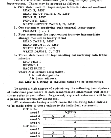
1-0
statementreferences
to FORMATnumbers
FORTRAN
11, Section One (704 Version)ASSEMBLY routine reads records from the BC;D input tape until a
statement and a l l its continuation cards a r e assembled in an erase-
able buffer termed the F- region. This region remains until replaced,
by the following statement. In order to ascertain that all continuation cards have been read the program reads one record ahead into an a r e a
termed FT. Blank cards and comments cards a r e ignored.
A word of all-ones i s written after the l a s t non-blank word in the
F-
region to serve a s an end-of-statement marker.An internal statement number O((1FN) i s assigned.
If an external statement number (EFN) appears in the source state-
ment it i s converted to binary and following table entry made: TEIFNO table
word 1
1
(X(1FN) O((EFN)
(
Any special mode character in cc 1 a r e isolated and saved.
CLASSIFICATION After assembly each statement i s classified accord-
ing to type. This classification is a two-phase procedure.
I. The sqatement i s classified as arithmetic if: 1) There exists an
=
sign not within "(" ")".2 ) This t sign is not followed by a t t
,
not within "('* ")".Control goes to the ARITHMETIC processor.
11. If the statement i s not classified a s .arithmetic by the above pro-
cedure it i s assumed to be non-arithmetic. The beginning of
statement i s compared to entries in a dictionary of non-arithmetic statement beginnings. When identified a s to type control goes to the appropriate processor. Failure to identify causes a Diagnostic message.
ARITHMETIC P r o c e s s o r
The reader is advised that this preliminary paper does not include a
description of
the
ARITHMETIC Proc,essor. A paper, describing thisprocessor from a theoretical standpoint, m a y be found in the commun-
ications of the Association for Computing Machinery, Vol. 2, No. 2,
FORTRAN 11, Section One (704 Version)
DIMENSIONS
V(
I ~ ,. . .
,
1 ~ 1 ~
V ( I ~ ,. .
.
,
1 ~ 1 ~
.
.
.
The statement i s scanned collecting the variable name V and assoc-
iated specification (Il,
.
.
,
Ik) where Kk
3. It i s verified that Vhas not been previously defined in a
DIMENSION
statement. Dimen-sionality i s based on the number of specifications Ikwhere 1
a.
K4
3. There a r e thus three possible cases:K
1.The
following table entry i s made:D I M table
word 1 V a r i a b l e N a m e (BCD)
1
word 2
1
0I
K
=
2. The following table entry i s made:DIM3 table
w o r d 1
I
V a r i a b l e N a m e (BCD)1
DIM2 table
L .#
word,l word 2
processed.
V a r i a b l e N a m e (BCD)
I1 12
word 2
word 3
Each specification of .equivalence i s scanned. The variable name i s
collected. The constant, i f present, i s collected and converted to binary.
If not present i t i s understood to be 1. The following table entry is made:
K
It 3. The following table entry i s made:I1
I20 Iq A
This procedure i s repeated until a l l V(Ip
.
,
.
Ik)
have beenOn the l a s t such the following table entry is made:
EQUIT table -
EQUIT
table 3word 1 V a r i - a b l e N a m e (BCD)
word 2
-
Nwhere the
-
signifies the end of a specification.The entire procedure i s repeated
for
each specification.word 1
word 2
V a r i a b J e N a m e (BCD)
N
whereN
i s the associated constant o r 1. 'FORTRAN 11, Section One (704 Version)
COMMON
Vl*
.
a VnEach variable name i s collected and the following table entry made: COMMON table
w o r d 1
I
V a r i a b l e N a m e (BCD)I
If the variable name i s fixed-point the following table entry i s made:
FORVAL
tableword 1
I
1 01
w o r d 2
1
V a r i a b l e N a m e(BCD)
1
The above procedure i s repeated for each argument name.
The statement i s scanned, collecting the statement number Bi. It i s converted to binary and the followjng table entry is made:
FRET
table 5word 1
I
-
0 Bi(EFN)I
Each branch frequency Ni i s collected and converted to binary. The following table entry is made:
FRET
tableword 1
I
0id
This i s repeated for each branch frequency. The entire procedure
END (11,
.
6 aIn)
is repeated for each specification.
Each specification is
END
table word 1collected and the following table entry made:
This is repeated for each specification.
FORTRAN
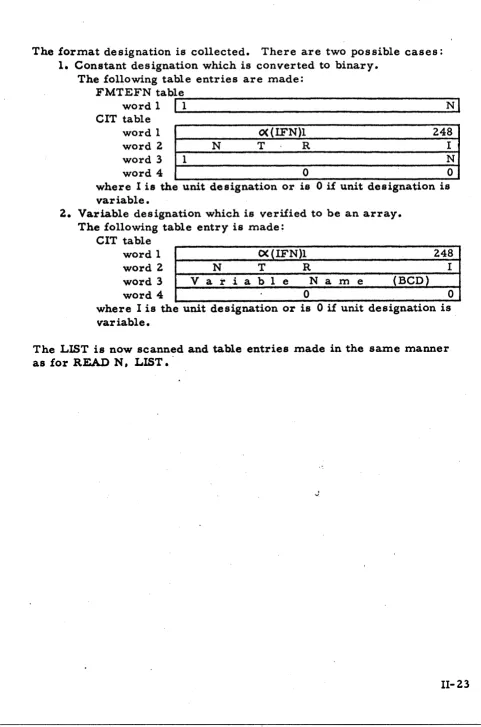
11, Section One (704 Version) FORMAT ( ..
.
)The following table entry is made: FORMA T table
w o r d 1 1 1 6C(EFN)
1
Each word of the
FORMAT
specification as found in the F-
region i smade into the following table entry:
FORMAT
tablew o r d 1 I ~ o r m a t S p e c i f i c a t i o n (BCD)
1,
The f i r s t word, if l e s s than eix characters, is prefaced by blanks.
When the entire Format specification has been entered the following
table entry i s made:
During the above procees&g
a
scan i s made of the Format specificationfor legality of charactere and balance of parenthesie (excluding hollerith
FORTRAN
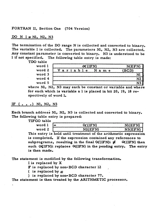
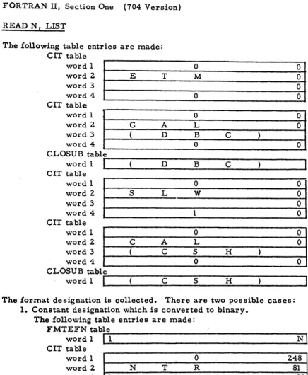
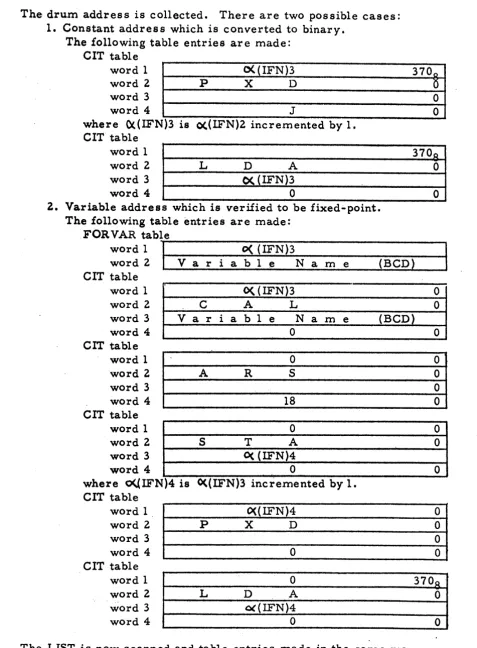
11, Section One (704 Version)The termination of the DO range N i s collected and converted to binary.
The variable I i s collected. The parameters M, N2, N3 a r e collected.
Any constant parameter i s converted to binary.
N3
i s understood to be1 if not specified. The following table entry i s made:
TDO table
word 3 1 N1 1
word 1 word 2
H
(IFN) N(EFN)V a r i a b l e N a m e
(BCD)
where N1, N2,
N3
may each be constant o r variable and whereword 4
word 5
for each which is variable a 1 i s placed in bit 20, 19, 18 re- ~2
N3
spectively of word 1.
Each branch address M,
NZ,
N3 i s collected and converted to binary.The following table entry is- prepared:
TIFGO table
This entry i s held until treatment of the arithmetic expressick
--- - - - -
is completed. If the expression contained any references to
subprograms, resulting in the final O((IFN)i
#
O((1FN) thensuch M I F N ) i replaces O((1FN) in the pending entry. The entry
is then made. word 1
word 2
The
statement is modified by the following transformation.I is replaced by
X
F
is replaced by non-BCD character 12 ,( is replaced by
=
) i s replaced by non-BCD character 77.
The statement i s then treated by the ARITHMETIC processor.
-
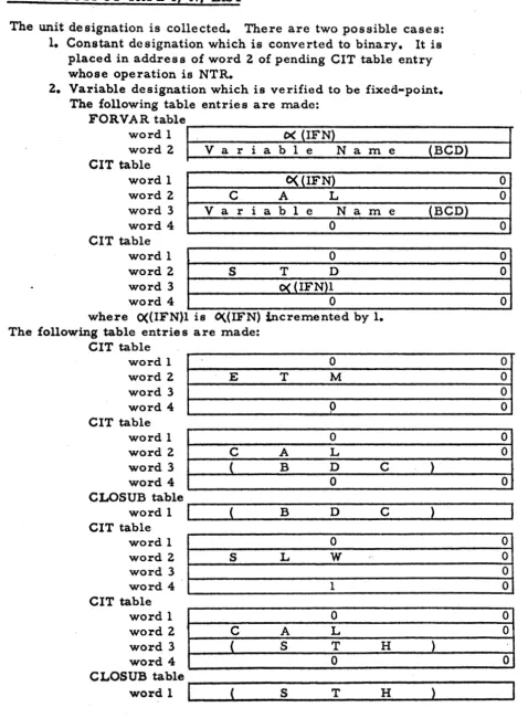
O((1FN) Nl(EFN) [image:26.614.50.534.45.763.2]FORTRAN
11, Section One (704 Version)IF ACCUMULATOR
OVERFLOW
Nl,
N2The branch addresses Nl, NZ a r e collected and converted to binary. The following table entries a r e made:
CIT table
IF QUOTIENT
OVERFLOW
M I
MZ word 1word 2
word 3
word 4
TIFGO
tableThe branch addresses N1, N2 a r e collected and converted to binary.
word 1
The following table entries a r e made:
q ( I F N ) 0
T 0 V 0
0
0 0
4
O((IFN) 5
CIT
tableword 1
word 2
word 3
word 4
TIF'GO table word 1
word 2
.I
word 2 L M ( E F N ) W ( E F N )
IF DIVIDE
CHECK
M, N2T h e
branch addresses N1, N2 a r e collected and converted to binary. The following table entries a r e made:CIT
tableword 1 word 2
word 3
word 4
TIFGO
table word 1word 2
FORTRAN
11, Section One (704 Version)SENSE
LIGHT
IIF (SENSE LIGHT I) M, N2
The sense light designation I i s collected. It i s converted to binary and
added to 14O8e The following table entry is made: CIT table
The sense light designation I i s collected. It i s converted to binary and
added to 1408. The following table entry is made:
b word 1 word 2
word 3
word 4
CIT table
word 1 C%
(IFN)
0o<
( I F N ) 0P
SE
00
A ( 1 4 0 , ~ I ) 0
word 2
1
M SE
The branch addresses
N1,
N2 a r e collected and converted to binary.The following table entry i s made:
word 3
word 4
TIFGO
tableword 1
I
31
0
(140R+ I ) 0
word 2
IF(SEMSE
SWITCH
I) N1, N2The sense switch designation I i s collected. It i s converted to binary and
added to
1608.
The following table entry is made:CIT table T
word I
,
The branch addresses Nl, N2 a r e collected and converted to binary.
- The following table entry i s made:
W
(IFN) 0'
word 3
word 4
word 2 P S
E
0 \0
(160R+1 ) 0
TIFGO
table word 1 word 2W (IFN 3
FORTRAN 11, Section One (704 Version)
The
The
branch a d d r e s s
N
i s collected and converted to binary. following table entries a r e made:CIT table word 1 word 2
word 3
word 4
TWGO table word 1
word 2
tX
(IFN)
0T R A. 0
Each
branch a d d r e s s Ni is collected and converted to binary. Thefollowing table entry i s made:
TRAD table
ward 1
I
0 Ni(EFN))'
This i s repeated for each Ni until i tr m e
Ni in
TRAD
table.The following table entry i s made:
TIFGO table
The variable I i s collected and treated by the subscript p r o c e s s o r as a word 1
one-dimensional subscript (I). The following table entry i s made:
o((1FN) 2
'
word 2 TRAD(Ni) TRAD(N&
where TRAD(Ni) i s the complement (table size) of position of
CIT table word 1
word 2
word 3 word 4
a ( I F N ) 0
T R A 0
0
0 1 - 7
FORTRAN
11, Section One (704 Version)GO TO N, (Il8 Iz8
. .
.
,
Im)Each permissible branch a d d r e s s
Ik
i s collected and converted to binary.The following table entry i s made: TRA D table
word 1
I
0 I ~ ( E F N #Tha
variableN
i a collected. The following table entry i s made: CIT tableword 1 word 2
word 3
word 4
Ik
in TRAD table.o<
(IFN) 0T
R
A 0V a r i a b l e N ' a m e
(BCD)
,
0 0This i s repeated for each Ik until k r m. The following table entry i s
made:
TIFGO table
ASSIGN I TO N
word 1
word 2
The
E F N being assigned (I) i s collected and converted to binary. The variable N i s collected. The following table entries a r e made:M
(IFN)
1TRAD(Il ) TRAD(
CIT table word 1 word 2
word 3
word 4
CIT
tableword 1
word 2
word 3
word 4
TIFGO table word 1
word 2
where TRAD(1k) i s the complement (table s i z e ) of
W (IFN) 0
<