ISSN (Online) : 2319 - 8753 ISSN (Print) : 2347 – 6710
International Journal of Innovative Research in Science, Engineering and Technology
An ISO 3297: 2007 Certified Organization Volume 7, Special Issue 5, April 2018
1st International Conference on Recent Innovation in Civil Engineering and Management (ICRICEM '18)
22nd March 2018 Organized by
Department of Civil Engineering & MBA, Loyola Institute of Technology, Chennai, Tamilnadu, India
Studies on Structural Behavior and
feasibility of construction methodology of
Bubble Deck Slab
S.Radha1 , N.Mareeswari Andal2
UG Student, Department of Civil Engineering, Jayaram College of Engineering and Technology, Trichy, India1
Teaching Fellow, Department of Civil Engineering, Jayaram College of Engineering and Technology, Trichy, India2
ABSTRACT: Bubble deck slab is a method of virtually eliminating all concrete from the middle of a floor slab, which is not performing any structural function, thereby dramatically reducing structural dead weight. High density polyethylene hollow spheres replace the in-effective concrete in the centre of the slab, thus decreasing the dead weight and increasing the efficiency of the floor. By introducing the gaps leads to a 30 To 50% lighter slab which reduces the loads on the columns, walls and foundations, and of course of the entire building. The advantages are less energy consumption - both in production, transport and carrying out, less emission - exhaust gases from production and transport, especially CO2 .The aim of this paper is to discuss about various properties of Bubble deck slab based on the
various studies done and different methodology of construction and different manufacturing techniques.
KEYWORDS: Biaxial Hollow core slabs, Bubble deck slab, Solid slab, concrete , steel , Hollow plastic spheres.
I.INTRODUCTION
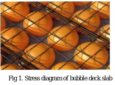
BUBBLE deck slab is a biaxial hollow core slab invented in Denmark. It is a method of virtually eliminating all concrete from the middle of a floor slab not performing any structural function (fig 1), thereby dramatically reducing structural dead weight. Bubble deck slab is based on a new patented technique which involves the direct way of linking air and steel. Void forms in the middle of a flat slab by means of plastic spheres eliminate 35% of a slab’s self-weight removing constraints of high dead loads and short spans. Its flexible layout easily adapts to irregular and curved plan configurations. The system allows for the realization of longer spans, more rapid and less expensive erection, as well as the elimination of down-stand beams. According to the manufacturer, Bubble deck slab can reduce total project costs by three percent. Bubble deck slab is a new innovative and sustainable floor system to be used as a self-supporting concrete floor. The application of the Bubble deck slab floor system in the Netherlands is manifested as the world-wide first application. The Bubble deck slab floor system can be used for storey floors, roof floors and ground floor slabs. A Bubble deck slab floor is a flat slab floor, therefore without beams and column heads. The principal characteristic is that hollow plastic spheres are incorporated in the floor, Clamped in a factory-made reinforcement structure. This reinforcement structure constitutes at the same as the upper and lower reinforcement of the concrete floor.
ISSN (Online) : 2319 - 8753 ISSN (Print) : 2347 – 6710
International Journal of Innovative Research in Science, Engineering and Technology
An ISO 3297: 2007 Certified Organization Volume 7, Special Issue 5, April 2018
1st International Conference on Recent Innovation in Civil Engineering and Management (ICRICEM '18)
22nd March 2018 Organized by
Department of Civil Engineering & MBA, Loyola Institute of Technology, Chennai, Tamilnadu, India
This is not the last of the advantages of the Bubble deck slab floor system: because of the lower weight of the floor system itself, also the supporting constructions such as columns and foundations can be less heavy. This can results eventually in a total weight or material saving on the building construction of up to 50 %. Since the weight of the structure reduced, this type of structure can useful to reduce earthquake damage.
Fig 1. Stress diagram of bubble deck slab
II. GEOTECHNICAL REQUIREMENTS
Bubble deck slab is composed of three main materials; they are steel, plastic spheres and concrete
2.1 Concrete : The concrete is made of standard Portlandcement with max aggregate size of 20 mm. No plasticizers
are necessary for concrete mixture.
Fig 2. Construction of Biaxial hollow core slab
2.2 Steel: The steel reinforcement is of grade Fy415 strengthor higher. The steel is fabricated in two forms –meshed
layers for lateral support and diagonal girders for vertical support of the bubbles.
ISSN (Online) : 2319 - 8753 ISSN (Print) : 2347 – 6710
International Journal of Innovative Research in Science, Engineering and Technology
An ISO 3297: 2007 Certified Organization Volume 7, Special Issue 5, April 2018
1st International Conference on Recent Innovation in Civil Engineering and Management (ICRICEM '18)
22nd March 2018 Organized by
Department of Civil Engineering & MBA, Loyola Institute of Technology, Chennai, Tamilnadu, India
III. PROPERTIES OF BUBBLE DECK SLAB
3.1 Flexural strength
Bubble deck slab is conceived to omit a significant volume of concrete (compared to a solid slab) in the central core where the slab is principally un-stressed in flexure [3]. In slabs, the depth of compressed concrete is usually a small proportion of the slab depth and this means that it almost always involves only the concrete between the ball and the surface so there is no sensible difference between the behavior of a solid slab and Bubble Deck. The only elements working are the outer ‘shell’ of concrete on the compression side and the steel on the tension side. In terms of flexural strength, the moments of resistance are the same as for solid slabs provided this compression depth is checked during design so that it does not encroach significantly into the ball refer Table 1 (a 20% encroachment has been shown to be insignificant).
3.2 Shear Strength
In any flat slab, design shear resistance is usually critical near columns. The shear stresses remote from the columns diminishes rapidly and outside the column zones it has been demonstrated by testing and calculation the transverse and longitudinal shear stresses are within the capacity of the Bubble deck slab system. Near the columns, bubbles are left out so in these zones a Bubble deck slab is designed exactly the same way as a solid slab. Shear resistance of Bubble deck slab is 0.6 times the shear resistance of a solid slab of the same thickness [3]. If this is exceeded by the applied shear, at a column for example, we leave out the balls and use the full solid shear values. Using Euro code 2, we would calculate the applied shear at 2d and subsequent perimeters from the column face as per the code requirements, as well as at the column face itself. We would then compare this to our calculated resistance. If the applied shear is less than the un-reinforced hollow slab resistance, no further check is required. If the applied shear is greater than the hollow slab resistance we omit balls and make it solid and then Check the solid part. The shear capacity is measured for two ratios of a/d (distance from imposed force to support divided by deck thickness). The results are shown in table 2. If the resistance is still greater than the solid slab resistance and less than the maximum allowed, we provide shear reinforcement. For these reasons, it is demonstrated that the design may be carried out in every way treating the slab as a solid slab, with the provisions mentioned above, which are all taken account of in the design process. We therefore use Euro code 2, which is fully compatible with the system, for our design and which is somewhat more up to date than BS8110. Punching shear [3] the average shear capacity is measured to 91 % compared to the calculated values of a solid deck.
Table 1
Comparison of bending strength in Bubble deck slab and solid slab [3]
In % of a
solid deck Bubble deck slabVs. Solid deck
Same Same
Same bending concrete strength stiffness volume
strength 100 105 150*
Bending
stiffness 87 100 300
Volume
of concrete 66 69 100
ISSN (Online) : 2319 - 8753 ISSN (Print) : 2347 – 6710
International Journal of Innovative Research in Science, Engineering and Technology
An ISO 3297: 2007 Certified Organization Volume 7, Special Issue 5, April 2018
1st International Conference on Recent Innovation in Civil Engineering and Management (ICRICEM '18)
22nd March 2018 Organized by
Department of Civil Engineering & MBA, Loyola Institute of Technology, Chennai, Tamilnadu, India
3.3 Durability
The durability of bubble deck slab is not fundamentally different from ordinary solid slabs. The concrete is standard structural grade concrete and combined with adequate bar cover determined in accordance with EC2 or BS8110[5] provides most control of durability commensurate with normal standards for solid slabs. When the filigree slabs are manufactured, the reinforcement module and balls are vibrated into the concrete and the standard and uniformity of compaction is such that a density of surface concrete is produced which is at least as impermeable and durable, arguably more so, to that normally produced on site. Bubble deck slab joints have a chamfer on the inside to ensure that concrete surrounds each bar and does not allow a direct route to air from the rebar surface. This is primarily a function of the fire resistance but is also relevant to durability.
Cracking in Bubble deck slab is not worse, and probably better, than solid slabs designed to work at the same stress levels. In fact Bubble deck slab possesses a continuous mesh, top and bottom, throughout the slab and this ensures shrinkage restraint is well provided for and that cracking is kept to a minimum whether it is intrinsic or extrinsic cracking. Unlike an off-the-shelf product, this is a system that is bespoke designed for each and every project. All the peculiarities of a project are therefore taken into account in the design; therefore there is no risk of the product being misused by applying it to uses for which it is not intended.
Table 2
Comparison of shear capacity in girders with solid deck and bubble deck slab [4]
Shear
capacity (in % a/d=2.15 a/d=3
of solid deck)
Solid deck 100 100
Bubble deck,
91 78 (81)
secured girders Bubble deck,
77 loose girders
3.4 Vibration
ISSN (Online) : 2319 - 8753 ISSN (Print) : 2347 – 6710
International Journal of Innovative Research in Science, Engineering and Technology
An ISO 3297: 2007 Certified Organization Volume 7, Special Issue 5, April 2018
1st International Conference on Recent Innovation in Civil Engineering and Management (ICRICEM '18)
22nd March 2018 Organized by
Department of Civil Engineering & MBA, Loyola Institute of Technology, Chennai, Tamilnadu, India
3.5 Fire Resistance
The fire resistance [8] of the slab is a complex matter but is chiefly dependent on the ability of the steel to retain sufficient strength during a fire when it will be heated and lose significant strength as the temperature rises. The temperature of the steel is controlled by the fire and the insulation of the steel from the fire. In any case, all concrete is cracked and, in a fire, it is likely that the air would escape and the pressure dissipated. If the standard bubble material is used (HDPE), the products of combustion are relatively benign, certainly compared to other materials that would also be burning in the vicinity. In an intense, prolonged fire, the ball would melt and eventually char without significant or detectable effect. Fire resistance depends on concrete cover nearly 60-180 minutes. Smoke Resistance is about 1.5 times the fire resistance. Depth of smokeless is than 10 m on both sides. Balls simply carbonize. No toxic gasses will be released [4].
Table 3
Sound insulation test results [5]
3.6 Deflection
Span depth ratio calculations for deflections are very approximate and are not appropriate in flat slabs of irregular layout except for the most simple or unimportant cases. FE modeling, including non-linear cracked section analysis is used to calculate the deflection using normal structural concrete with a Young’s Modulus (secant) Ecm,
multiplied by 0.9 and a tensile strength, fctm multiplied by 0.8 (to reduce the crack moment as mentioned above. This
is mainly significant in the computation of uncracked curvatures where the geometry of the concrete section is significant but is of increasingly negligible significance after cracking). The deflections in Bubble deck slab and solid slab are explained in terms of stiffness as shown in table 1[6]. It is not presently possible to calculate for the difference in age related properties in the filigree and in-situ concrete parts. This is not considered to be a significant weakness.
3.7 Sound Insulation
ISSN (Online) : 2319 - 8753 ISSN (Print) : 2347 – 6710
International Journal of Innovative Research in Science, Engineering and Technology
An ISO 3297: 2007 Certified Organization Volume 7, Special Issue 5, April 2018
1st International Conference on Recent Innovation in Civil Engineering and Management (ICRICEM '18)
22nd March 2018 Organized by
Department of Civil Engineering & MBA, Loyola Institute of Technology, Chennai, Tamilnadu, India
3.8 Contact between bubbles and Reinforcements
The potential for any contact is only theoretical because the balls do not perfectly fit between reinforcement bars and moves slightly during assembly / site concrete compaction so that some grout surrounds it and provides a measure of passivation. However, even if there were contact between the ball and the steel, the environment inside the void is very dry and protected - there is also no breach (apart from micro cracking) of the concrete to the outside air. It is a better situation than exists with inclusion of plastic rebar spacers within solid slabs that create a discontinuity within the concrete between the outside air and the rebar in solid reinforced concrete slabs. We therefore have a situation that is better than existing with plastic rebar spacers and these have been permitted for many years. Tests carried out in Denmark, Germany and Holland showed that the flexural stiffness is approximately 87% to 93% of the same thickness of solid slab - In design we use an average of 90% and, in addition, the cracking moment is factored by 80% as recommended in Dutch research. In fact one of the major benefits of the system is its virtue of reducing deflections for a given span because the one-third weight reduction overwhelmingly more than compensates for the very small reduction in stiffness.
IV. METHODOLOGY
The actual construction of the bubble deck incorporates what is known as biaxial slab, meaning that two wire grids rest on a ball. Each of these grids can be placed between slabs of concrete, with numerous balls closely arranged in a approximate grid form and a thinner grid is welded on top to form a “cage”. This cage is fixed into 3 inches of concrete to form a panel. The bubbles are made by embodying high density polypropylene in the concrete and placed between the reinforcement meshes. The material that are not react chemically with the concrete or the reinforcement, it has no porosity, has enough rigidity and strength to take over loads as much
as possible from the pouring of concrete.
The nominal diameter of bubble gaps may be 180,225,270,315 or 360mm. The minimum distance between gaps is 1/9 of the gaps diameter. The total height of the bubble deck slab elements is constant. Function of the diameter of bubbles that are used may be the total height of slab is 230,280,340,390 or 450mm. The weight of the bubble deck slabs are corresponds to the function of its dimensions. In order to increase the shear strength capacity and bending moment in the areas with stress concentration it is possible that in these areas gaps are not provided. Span of the slab various between 12m to 17m and width may be 2.4m or 3m. The concrete used for the precast layer can be of common concrete or self leveling concrete. Minimum grade of concrete that is used for the construction of slabs are M20 or M25.
The bubble deck slab gaps elements can be delivered by three versions that are
ISSN (Online) : 2319 - 8753 ISSN (Print) : 2347 – 6710
International Journal of Innovative Research in Science, Engineering and Technology
An ISO 3297: 2007 Certified Organization Volume 7, Special Issue 5, April 2018
1st International Conference on Recent Innovation in Civil Engineering and Management (ICRICEM '18)
22nd March 2018 Organized by
Department of Civil Engineering & MBA, Loyola Institute of Technology, Chennai, Tamilnadu, India
Fig.1: Version A – Reinforcement Modules.
Version B : Partial precast concrete elements. They have the bottom part made of precast concrete and the connections between elements and the over concreting are cast in place.
Fig.2: Version B – Filigree Elements.
Version C : Finished plank is a shop-fabricated module that includes the plastic spheres, reinforcement mesh and concrete in its finished form. The module is manufactured to the final depth in the form of a plank and is delivered on site. Unlike, version A and B, it is a one-way spanning design that requires the use of support beams or load bearing walls. This class of Bubble Deck is best for shorter spans and limited construction schedules.
Fig.3: Version C - Finished Plank.
V. MANUFACTURING
In order to achieve the reinforcement modulus for bubble deck slabs with gabs the following operations must take place.
Version A
a) Making the reinforcement meshes.
b) Placing the pipelines, cables and element of electric fitting if in case.
ISSN (Online) : 2319 - 8753 ISSN (Print) : 2347 – 6710
International Journal of Innovative Research in Science, Engineering and Technology
An ISO 3297: 2007 Certified Organization Volume 7, Special Issue 5, April 2018
1st International Conference on Recent Innovation in Civil Engineering and Management (ICRICEM '18)
22nd March 2018 Organized by
Department of Civil Engineering & MBA, Loyola Institute of Technology, Chennai, Tamilnadu, India
d) Placing of the polypropylene spheres between the meshes according to plan. e) Labeling of the reinforcement modules.
Version B
a) Making of the reinforcement meshes.
b) Placing of the installation on the reinforcement meshes.
c) Fixing small boxes or pieces of polypropylene on reinforcement meshes or directly on the formwork for marking the portion of the walls or the columns and installation.
d) Placing of polypropylene spheres between the meshes according to planes. e) Preparing the formwork. (cleaning, assembling, greasing)
f) Checking of the formwork and the reinforcement before pouring the concrete. g) Preparing the concrete.
h) Pouring the concrete.
i) Foreseeing labels on elements.
VI. CASTING
Making cast in place slabs.
o The formwork is made with supports calculated to hold the concrete’s own weight and the loads that occur during pouring the concrete.
o The reinforcement is placed according to the planes. o The position of the spheres is checked.
o Placing the reinforcement at the connection with the columns or the wall areas. o The concrete M20/M25 is poured and vibrated.
o The supports of the formwork and the formwork are removed when the slab is able to take over the own weight and the live loads.
Making the semi precast concrete slabs.
o Each slab element needs to be temporary propped. The supporting elements need to be dimensioned so they can take over the weight of the semi precast elements, the reinforcement and the fresh concrete and also all the loads that occurs until the operation of concreting is finished.
o The distance between the supporting beams should not be larger than 1800mm.
o The temporary propping elements are kept in position until each part of the slab can support by itself. o The transversal reinforcement bars must be embedded in the adjacent slab elements.
o In case that geometrical misshapes occur the adjustments of the element is possible by the means of a diamonded disk that creates the area that takes over shear force. In these situations the integrity of the top part mesh is assured and also of the inclined reinforcement.
o In this phase, the polypropylene pieces that mark the position of different elements are removed.
ISSN (Online) : 2319 - 8753 ISSN (Print) : 2347 – 6710
International Journal of Innovative Research in Science, Engineering and Technology
An ISO 3297: 2007 Certified Organization Volume 7, Special Issue 5, April 2018
1st International Conference on Recent Innovation in Civil Engineering and Management (ICRICEM '18)
22nd March 2018 Organized by
Department of Civil Engineering & MBA, Loyola Institute of Technology, Chennai, Tamilnadu, India
o Immediately after pouring, the surface of the concrete is cleaned with under pressure water to remove the dust and to moisture the surface. Especially in times of high temperature the surfaces of the precast elements is kept wet to ensure the needed adherence.
Bubble deck with gaps reinforced on two directions, assures the mechanical strength and stability of construction by designing of the slab by calculating it for stresses given by dead and live loads. Reducing the weight of the construction loads is to reducing of the calculus seismic force. Bubble deck slabs with gaps are not toxic and environmental friendly, doesn’t diffuse noxious substances and they are not radioactive and also reduce the quantity of carbon emitted.
ADVANTAGES:
1) SUPIRIOR STATICS:
It helps to reduce the self weight or dead weight up to 50% Larger spans (L/36) and larger overhangs (L/10) can be achieved. No beams or ribs under the ceiling, pillars have no capital. It needs only less number of columns.
2) PRODUCTION AND CARRYING OUT:
Higher quality through automated production of prefabricated units. Less work in in situ.
Easier and more simple erection. Less storage space.
Light and cheap lifting equipment. 3) SAFETY:
Fireproof construction.
Earthquake- Safety will benefits significantly alone from the weight reduction. Moisture- Condensation- safe construction.
4) ECONOMIC SAVING:
Savings in materials are substantial up to 50% Subsequent works are simplified.
Buildings are more flexible. Life span of buildings is longer.
Manual mounting of reinforcement meshes o the building site is avoided.
5) ENVIRONMENTAL IMPROVEMENT:
Less energy consumption- both in production, transport and carrying out. Less emission- exhaust gases from production and transport, especially co2S.
No waste generation- 100% recycling. Improvement of working conditions.
Reduced building time means less disturbances of surroundings. Less emission of noise- in production, transport and assembly.
ISSN (Online) : 2319 - 8753 ISSN (Print) : 2347 – 6710
International Journal of Innovative Research in Science, Engineering and Technology
An ISO 3297: 2007 Certified Organization Volume 7, Special Issue 5, April 2018
1st International Conference on Recent Innovation in Civil Engineering and Management (ICRICEM '18)
22nd March 2018 Organized by
Department of Civil Engineering & MBA, Loyola Institute of Technology, Chennai, Tamilnadu, India
DISADVANTAGES:
Lack of skilled labors – If the construction worker substitute the bubbles in the place of concrete at the support region, it might prove disastrous.
Fitting of hollow plastic bodies in between lower steel mesh and upper steel mesh is always done in high position where a bubble deck is casted, productivity of engineers and workers thus is being reduced much at the same time casting more time due to travel up and down or in case of casting concrete deck covered thousand square meter.
Costing much money for building formwork system.
Requiring specialized welding machines and much time to weld spacers to connect lower and upper steel mesh. Moreover, structure with too much welding joints may change the properties of steel and reduce the durability of deck structure.
Because spherical plastic bodies are hollow, these plastic bodies will float on to the surface as pouring concrete causing thrust and unstable structure.
Costing much money for building of factories or workshop to manufacture deck elements.
Costing much money for transport these structures to construction sites. Besides, the thin concrete layer may be broken during transportation.
Because hollow concrete deck structure is heavy, It is essential to use huge capacity crane to lift these structure to the planned position and it is also very difficult for crane to access the desired position.
Costing more steel used to fabricate stiffeners which are used to move and lift deck structure.
Due to the thin concrete layer is not at the same time casted with the concrete casted at construction sites, thus there is no integrity between them. This reduces technical efficiency and durability of bubble deck elements. IS codal – The scope of our codal provisions aren’t that wide and experimenting with new tech isn’t
something which is easy at that moment.
VII. CONCLUSION
The construction floors in the building industry consists mainly of massive concrete floors, prefabricated filigree slab floors and hollow core slab floors. This situation has not changed for more than 20 years. But this innovative bubble deck slab construction technology is proven to be more efficient than a traditional biaxial concrete slab in an office floor system. As it saves the cost of building and reduces nearly 50% of self weight of the building.
Thus, the studies on a variety of methodology and construction techniques to determine the feasibility of bubble deck slab in a commercial and high rise buildings construction are discussed on brief.
REFERENCES
1. Tina Lai ”Structural behavior of bubble deck slab and their applications to lightweight bridge decks” ,M.Tech thesis, MIT, 2009. 2. Sergiu Calin, Ciprian Asavoaie and N. Florea, “Issues for achieving an experimental model” Bul. Inst. Polit. Iaşi, t. LV (LIX), f. 3, 2009. 3. Martina Schnellenbach-Held and Karste Pfeffer,”Punching behavior of biaxial hollow slabs” Cement and Concrete Composites, Volume 24,
Issue 6, Pages 551-556, December 2002.
ISSN (Online) : 2319 - 8753 ISSN (Print) : 2347 – 6710
International Journal of Innovative Research in Science, Engineering and Technology
An ISO 3297: 2007 Certified Organization Volume 7, Special Issue 5, April 2018
1st International Conference on Recent Innovation in Civil Engineering and Management (ICRICEM '18)
22nd March 2018 Organized by
Department of Civil Engineering & MBA, Loyola Institute of Technology, Chennai, Tamilnadu, India
5. Sergiu Calin and Ciprian Asavoaie, “Method for Bubble deck slab concrete slab with gaps”, The Buletinul Institutului Politehnic din Iasi, LV (LIX), f. 2,2009.
6. Sergiu Calin, C. Mugurel, G. Dascalu, C Asavoaie, “Computational simulation for concrete slab with spherical gaps”, Proceedings of The 8-th International Symposium, Concepts in Civil Engineering, Ed. Societatii Academice "Matei-Teiu Botez", 2010, pp. 154-161.
7. BubbleDeck voided Flat Slab Solutions- Technical Manual and Documents,Version:5, Issue 1, BubbleDeck UK, White Lodge, Wellington Road, St Saviour, JERSEY, C.I.,2008,Available: www.BubbleDeck-UK.com.
8. BubbleDeck Engineering Design & Properties Overview – Technical Manual and Documents, Issue 3, BubbleDeck UK, White Lodge, Wellington Road, St Saviour, JERSEY,C.I.,2007,Availa.
9. BubbleDeck Acoustic Tests and Reports, Issue:4,BubbleDeck UK, White Lodge, Wellington Road, St Saviour, JERSEY, C.I.,2006,Available: www.BubbleDeck-UK.com
10. BubbleDeck Fire resistance Tests and Reports, Test Report D3,BubbleDecak UK, White Lodge, Wellington Road, St Saviour, JERSEY, C.I.,2002,Available: www.BubbleDeck-UK.com.
11. Tina Lai ”Structural behavior of bubble deck slab and their applications to lightweight bridge decks” ,M.Tech thesis, MIT, 2009. 12. Sergiu Călin, Ciprian Asăvoaie and N. Florea, “Issues for achieving an experimental model” Bul. Inst. Polit. Iaşi, t. LV (LIX), f. 3, 2009. 13. Martina Schnellenbach-Held and Karsten Pfeffer,”Punching behavior of biaxial hollow slabs” Cement and Concrete Composites, Volume
24,Issue 6, Pages 551-556, December 2002.
14. Sergiu Călin, Roxana Gînţu and Gabriela Dascălu, ”Summary of tests and studies done abroad on the Bubble deck slab system”, The Buletinul Institutului Politehnic din Iaşi, t. LV (LIX), f. 3, 2009.
15. Sergiu Calin and Ciprian Asavoaie, “Method for Bubble deck slab concrete slab with gaps”, The Buletinul Institutului Politehnic din Iaşi, LV (LIX), f. 2,2009.
![Table 1 Comparison of bending strength in Bubble deck slab and solid slab [3]](https://thumb-us.123doks.com/thumbv2/123dok_us/1501185.1183767/3.595.53.436.542.754/table-comparison-bending-strength-bubble-deck-slab-solid.webp)
![Table 2 Comparison of shear capacity in girders with solid deck and bubble deck slab [4]](https://thumb-us.123doks.com/thumbv2/123dok_us/1501185.1183767/4.595.164.431.477.587/table-comparison-shear-capacity-girders-solid-deck-bubble.webp)
![Table 3 Sound insulation test results [5]](https://thumb-us.123doks.com/thumbv2/123dok_us/1501185.1183767/5.595.162.436.378.530/table-sound-insulation-test-results.webp)
