ISSN(Online): 2320-9801
ISSN (Print): 2320-9798
I
nternational
J
ournal of
I
nnovative
R
esearch in
C
omputer
and
C
ommunication
E
ngineering
(An ISO 3297: 2007 Certified Organization)
Vol. 3, Issue 7, July 2015
Smart Highways Systems for Future Cities
Anshu Adwani1, Kirti H. Madan2, Rohit Hande3
Lecturer, Dept. of ENTC Engineering, DMIETR, Sawangi (Meghe), Wardha, Maharashtra, India1
Lecturer, Dept. of Electronics & Tele-Comm. Engineering, A.S. Polytechnic, Pipri, Wardha, Maharashtra, India2
Lecturer, Dept. of ENTC Diploma, DMIETR, Sawangi (Meghe), Wardha, Maharashtra, India3
ABSTRACT: An intelligent Highway is an innovative concept for smart roads of future smart cities. It is a program of innovation that links a different way of looking at things with innovative ideas that apply the opportunities offered by new technologies in smart ways. Nowadays safety on road has become an important factor in our life because there is an increasing amount of accidents on the road and there are some places where accident occur frequently such as crossings, turns. Also there is a big problem of traffic jams on the road. Due to heavy rain fall, there is a possibility of water overflow on the bridges and accident may occur. In hilly area there is a possibility of landslide. so, there came a need to design a system which can detect these unexpected events. So we are designing a system that is “An Intelligent Highway system with (Weather Accidents Landslides and traffic) W.A.L.T.” which is an innovative concept to maintain safety on roads. The system will make use of digital sensor to acquire data of landslide, accidents traffic jams and weather condition and that will be displayed on active LED display on road, using XBee and GSM technologies.
KEYWORDS: Accidents, Smart highways, XBee, landslides.
I. INTRODUCTION
This paper proposes a system for smart highways of future cities. Common city roads have to face many problems such as traffic jams which cause loss of valuable time. And also there is no display indication on our roads for showing traffic conditions in the city. This paper proposed a wireless sensor based system which will be situated in the city roads and read the traffic data and send it to the displays or road signs which are digital led boards providing information about all data. The second part of system consist accident detection system based on the sound sensor it records the sound of accident and with the help of that it decides whether accident has happen or not depending on intensity of sound and if accident get detected it will send MSG through GSM modem to nearest police station and hospital. The next provision in this system will be of bridge overflow detection. In many areas water flows over the bridges in monsoon and that causes heavy traffic jams and kilometre long lines of vehicles. To avoid this water overflow sensor will read the water data of the river bridge and send to control station which will send this to active LED road signs where that will be displayed. The fourth provision is for the landslides happening in the hilly areas which are the cause of traffic jams and heavy loss. The areas where landslide happens are located in remote parts so very few communication devices are available there. In this using ultrasonic sensor based landslide detector sensor will be placed at such places which will detect landslide and send information to the disaster management system using GSM or XBee.
II. RELATED WORK
ISSN(Online): 2320-9801
ISSN (Print): 2320-9798
I
nternational
J
ournal of
I
nnovative
R
esearch in
C
omputer
and
C
ommunication
E
ngineering
(An ISO 3297: 2007 Certified Organization)
Vol. 3, Issue 7, July 2015
groups represent individual vehicle trajectories, which can be used to measure traditional traffic parameters as well as new metrics suitable for improved automated surveillance. The system works by using latest technologies like digital image processing not use that node.
III. PROPOSED SYSTEM
A. Design Considerations:
Sensor arrays for detecting traffic jams. Water detector sensors over every bridge Landslide detector Sensors.
Accident detector sensors. Active Led display boards.
B. Block diagram of the Proposed System:
Fig.1 Block diagram of transmitter section
The block diagram of system shows all basic components of the smart highways. Various sensors that are connected to a microcontroller which is Arduino ATMega 328 an AVR core based microcontroller. All the data from sensors is read by the microcontroller and particular information is sent by GSM and XBee. As shown in the block diagram, transmitter section consist of the four sensors, one microcontroller, one GSM modem, XBee transmitter. If any condition occurs it is detected by particular sensor and information about the event is given to the microcontroller. Microcontroller is heart of the system which controls all the operation related to the accident, landslide, and water overflow on the bridge and traffic jam. The message will be sent to ambulance and disaster relief team with GSM
Controller
GSM
Modem
XBee
Transmitter
Accident
Sensor
Weather
Sensor
Land Slide
Sensors
ISSN(Online): 2320-9801
ISSN (Print): 2320-9798
I
nternational
J
ournal of
I
nnovative
R
esearch in
C
omputer
and
C
ommunication
E
ngineering
(An ISO 3297: 2007 Certified Organization)
Vol. 3, Issue 7, July 2015
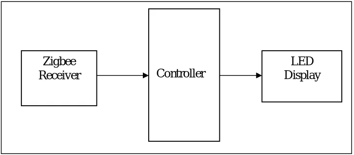
modem. With the help of the XBee transmitter message will be transmit to the receiver section This section consist of one XBee receiver, one microcontroller and one LED board.
Fig. 2 Block diagram of Receiver side
The message will be received by receiver section and displayed by LED board. XBee operates in 16 channel of 2.4GHz band and provides a data of 250Kbps.It has been designed for single channel 868MHz, which provides 20 Kbps in Europe and 10 channel 915 MHz It provides 40 Kbps in America. A XBee device can function either a node or as a coordinator. A node is like client or slave device that can receives command or data from the coordinator. A node cannot initiate connection with other nodes. Coordinator can control up to 255 nodes. XBee devices can form PAN using mesh, star or cluster topology. Multiple network coordinators can be linked together to form large network coordinators can be linked together to form control up to 65,536 devices. Advanced encryption services (AES) will enable highly secured services networks and applications profile will provide highly interpretable products and solutions. The focus of network applications under the IEEE 802.15.4 / XBee standard include the features of low power consumption, needed for only two major modes (Tx/Rx or Sleep), high density of nodes per network, low costs and simple implementation with 2.4GHz and 868/915 MHz dual PHY modes. This represents three license-free bands: 2.4-2.4835 GHz, 868-870 MHz and 902-928 MHz. The number of channels allotted to each frequency band is fixed at sixteen (numbered 11-26), one (numbered 0) and ten (numbered 1-10) respectively. The higher frequency band is applicable worldwide, and the lower band in the areas of North America, Europe, Australia and New Zealand. Low power consumption, with battery life ranging from months to years is the need of every area. Considering the number of devices with remotes is used at present, it is easy to see that more numbers of batteries need to be provisioned every so often, entailing regular (as well as timely), recurring expenditure. In the XBee standard, longer battery life is achievable by either of two means: continuous network connection and slow but sure battery drain, or intermittent connection and even slower battery drain.
LED
Display
Controller
ISSN(Online): 2320-9801
ISSN (Print): 2320-9798
I
nternational
J
ournal of
I
nnovative
R
esearch in
C
omputer
and
C
ommunication
E
ngineering
(An ISO 3297: 2007 Certified Organization)
Vol. 3, Issue 7, July 2015
No No No No
Yes Yes Yes Yes
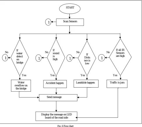
Fig. 4 Flow chart
As shown in the block diagram, transmitter section consist of the four sensors, one microcontroller, one GSM modem, XBee transmitter. If any condition occurs it is detected by particular sensor and information about the event is given to the microcontroller. Microcontroller is heart of the system to control all the operation related to the accident, landslide, water overflow on the bridge and traffic jam. The message will be ambulance and disaster relief team with GSM modem. With the help of the XBee transmitter message will be transmit to the receiver section This section consist of one XBee receiver, one microcontroller and one LED board. The message will be received by receiver section and displayed by LED board.
START
Scan Sensors
If water detect on bridge
Water overflow on
the bridge
Accident happen Landslide happen Traffic is jam
Send message
Display the message on LED board of the road side
1
1
1
If sound is high
If Dista nce is
low
If all IR Sensors are high
ISSN(Online): 2320-9801
ISSN (Print): 2320-9798
I
nternational
J
ournal of
I
nnovative
R
esearch in
C
omputer
and
C
ommunication
E
ngineering
(An ISO 3297: 2007 Certified Organization)
Vol. 3, Issue 7, July 2015
IV. PROTOTYPE CIRCUIT DIAGRAM
Fig. 5.Circuit diagram
ISSN(Online): 2320-9801
ISSN (Print): 2320-9798
I
nternational
J
ournal of
I
nnovative
R
esearch in
C
omputer
and
C
ommunication
E
ngineering
(An ISO 3297: 2007 Certified Organization)
Vol. 3, Issue 7, July 2015
SIM900 GSM module which is manufactured by SIM Com. Designed for global market, SIM900 is a quad-band GSM/GPRS engine that works on frequencies GSM 850MHz, EGSM 900MHz, DCS 1800MHz and PCS 1900MHz. SIM900 features GPRS multi- slot class 10/ class 8 (optional) and supports the GPRS coding schemes 1, 2, CS-3 and CS-4. With a tiny configuration of 24mm x 24mm x CS-3mm, SIM900 can meet almost all the space requirements in User’s applications, such as M2M, smart phone, PDA and other mobile devices.
V. SIMULATION RESULTS
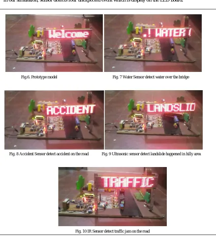
In our simulation, sensor detects four unexpected event which is display on the LED board.
Fig.6. Prototype model Fig. 7 Water Sensor detect water over the bridge
Fig. 8 Accident Sensor detect accident on the road Fig. 9 Ultrasonic sensor detect landslide happened in hilly area
ISSN(Online): 2320-9801
ISSN (Print): 2320-9798
I
nternational
J
ournal of
I
nnovative
R
esearch in
C
omputer
and
C
ommunication
E
ngineering
(An ISO 3297: 2007 Certified Organization)
Vol. 3, Issue 7, July 2015
Above pictures displays the working of proposed system. Fig 6 shows all prototype models within normal working condition which will display welcome message on the display board. Figs 7 displays the working condition when there is water overflow occurs on the bridge which is sensed by the level sensor and data sent to the board through GSM and XBee which will be displayed on the board using microcontroller. In the next figure i.e. fig.8 Accident detection process is shown. Accident will be detected by the MEMS sound sensors and data will be shown on display. If any landslides happen in area, it will be detected by the ultrasonic distance detecting sensor and message will be displayed on the LED board. Fig. 10 shows the traffic congestion condition in city which is detected by the sensor array and if all the sensors are found high then it is displayed on the LED board. In this way, all the sensor data is displayed on the LED board which is very useful for people travelling in the highways.
VI. CONCLUSION AND FUTURE WORK
In this paper, a novel idea is proposed for monitoring the accident over the road. Landslide and water overflow on bridge is detected with the help of using different sensors. Also with the help of GSM modem, message will be sent to the natural disaster management, hospital, police station and message is also displayed on the LED display. In this landslide in hill area is detected by using ultrasonic sensor, water overflow on bridge is detected by using water sensor, and accident on road is detected by using sound sensor, traffic jam on the road is detected by using IR sensor. The GSM is used to send the message. The massage can be transmitted to each receiver separately using XBee technology in mesh networking. Also the message is displayed on the LED board performance.
REFERENCES
1. Automatic Vehicle Accident Detection System Based on ARM &GPSNiravThakor1, TanmayVyas2, DivyangShah.International Journal for Research in Technological Studies ISSN: - Applied (Online) Vol-1, Issue - 1, Dec 2013
2. Traffic Jam Detection Using Image Processing Prof. Uma Nagaraj*, Jinendra Rathod*, PrachiPatil*,Sayali Thakur*,Utsav Sharma*
International Journal of Engineering Research and Applications (IJERA) ISSN: 2248-9622www.ijera.com Vol. 3, Issue 2, March -April 2013, pp.1087-1091
3. Zutao Zhang, Jiashu Zhang, “A Novel Vehicle Safety Model: Vehicle speed Controller under Driver Fatigue”, IJCSNS International Journal of Computer Science and Network Security, VOL.9 No.1, January 2009.
4. M. Bertozzi, A. Broggi, M. Cellario, A. Fascioli, P. Lombardi, and M.Porta, “Artificial vision in road vehicles”, Proceedings of the IEEE,
vol. 90,no. 7, pp. 1258–1271, 2002.
5. S. Tsugawa and Sadayuki, “Vision-based vehicle on Japan: Machine vision systems and driving control systems”, vol. 41, no. 4, pp. 398–
405, 1994.
6. Qingfeng Huang and Ying Zhang,“Dynamic balancing of push and pull in distributed traffic information system”, In IEEE Consumer