ISSN(Online): 2320-9801
ISSN (Print): 2320-9798
International Journal of Innovative Research in Computer
and Communication Engineering
(An ISO 3297: 2007 Certified Organization)
Vol. 3, Issue 8, August 2015
Diagnose Movements of Object using Face
Tracking in Wireless Sensor Networks
Raju Dole, M.Srinivasulu, Bullarao Domathoti
Pursuing M. Tech, Dept. of ECE., SITS, JNT University, Ananthapuram, AP, India
Associate Professor, Dept. of ECE., SITS, JNT University, Ananthapuram, AP, India
Assistant Professor, Dept. of CSE., SITS, JNT University, Ananthapuram, AP, India
ABSTRACT: Target following is one in every of the key applications of wireless detector networks (WSNs). Existing work largely needs organizing teams of detector nodes with measurements of a target’s movements or correct distance measurements from the nodes to the target, and predicting those movements. These are, however, typically troublesome to accurately attain in apply, particularly within the case of unpredictable environments, detector faults, etc. during this paper, we tend to propose a replacement following framework, referred to as Face Track, that employs the nodes of a abstraction region close a target, referred to as a face. rather than predicting the target location singly during a face, we tend to estimate the target’s moving toward another face. we tend to introduce a grip detection formula to come up with every face more in such away that the nodes will prepare prior the target’s moving, that greatly helps following the target during a timely fashion and sick from special cases, e.g., detector fault, loss of following. Also, we tend to develop Associate in Nursing optimum choice formula to pick out that sensors of faces to question and to forward the following knowledge. Simulation results, compared with existing work, show that Face Track achieves higher following accuracy and energy potency. we tend to conjointly validate its effectiveness via a proof-of-concept system of the Imote2 detector platform.
KEYWORDS: energy Wireless sensor networks, target tracking, sensor selection, edge detection, face tracking, fault tolerance
I. INTRODUCTION
Wireless detector networks (WSNs) have gained plenty of attention in each the general public and therefore the analysis communities as a result of they're expected to bring the interaction between humans, environments, and machines to a replacement paradigm. WSNs were originally developed for military functions in parcel surveillance; but, the event of such networks has inspired their use in attention, environmental industries, and for observance or pursuit targets of interest.
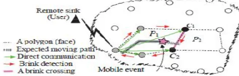
Fig. 1 illustrates a typical state of affairs of associate degree enemy vehicle pursuit application. detector nodes square measure familiar once the vehicle underneath police investigation is discovered, whereas some nodes (such as black nodes) observe the vehicle and send a vigilance message to the nodes on the vehicle’s expected moving path, therefore on wake them up. Thus, the nodes (such as gray nodes) within the vehicle’s moving path will prepare before and stay alert before of it because it moves. To be energy economical and to accurately track the vehicle, solely the nodes near the trail will participate in pursuit and providing continuous coverage.
ISSN(Online): 2320-9801
ISSN (Print): 2320-9798
International Journal of Innovative Research in Computer
and Communication Engineering
(An ISO 3297: 2007 Certified Organization)
Vol. 3, Issue 8, August 2015
Regardless of numerous styles of targets , there square measure 3 common procedures concerned in existing solutions of target tracking:
1) detector nodes ought to be localized with as few errors as attainable, and a distance mensuration from the nodes to a target, or a mensuration of the target’s movements is crucial;
2) Nodes ought to be organized into teams (e.g., clusters) to trace a mobile target; 3) Leader sensors usually report the target’s movement to a central sink (or a user)—the sink may be a resource-rich node that gathers info from the leaders. Benefits:
Some edges of Face Track square measure highlighted, that facilitate US reach our objectives.
1. When a happening of detector fault happens, or there's a happening of loss of pursuit, Face Track mitigates
such events while not recalibrating the complete network.
2. Nodes regionally observe the presence of the target and judge whether or not to continue pursuit tasks, i.e., they are doing not ought to communicate with the sink oftentimes. However, the sink is familiar by the couple nodes whether or not or not the target enters the police investigation space.
3. Nodes don't predict or maintain the target’s movement history fully, however keeps solely the foremost
recently rumored info and time instance.
4. If the quantity of active nodes is massive, the pursuit accuracy is higher; however the energy price is higher
too. Face Track depends on accumulated detection from a specific variety of nodes that square measure within the polygons. The four main contributions of this paper square measure as follows:
II. LITERATUREREVIEW
Distributed RSSI process for Intrusion Detection in Indoor Environments
In the context of WSNs, the RSSI has been historically exploited for localization, distance estimation, and link quality assessment. Recent analysis has shown that variations of the signal strength in indoor environments wherever nodes are deployed will reveal movements of persons. Moreover, the time-histories of the RSSI over multiple links permit reconstructing the methods followed by the persons within the monitored space.This approach, though' effective, needs the transmission of multiple entire RSSI time-histories to a sink wherever these signals square measure processed, increasing latency and power consumption. This work aims at applying distributed process of the RSSI signals for intrusion detection. Through distributed process, the nodes square measure ready to observe and localize moving persons autonomously. The latency and power consumption of the planned intrusion detection system is reduced by transmittal to the sink solely alert notifications associated with important events. Moreover, associate degree correct time-synchronization permits the nodes to stay the radio off most of the time.
pursuits with Unreliable Node Sequence:
Tracking mobile targets victimization detector networks may be a difficult task attributable to the impacts of in-the-filled factors like surroundings noise, sensing irregularity and etc.This paper proposes a strong pursuit framework victimization node sequences, associate degree ordered list extracted from unreliable detector readings.Rather than estimating every position purpose on an individual basis during a movement trace,we have a tendency to convert the first pursuit downside to the matter of finding the shortest path during a graph, that is adore best matching of a series of node sequences.Additionally to the essential style, multidimensional smoothing is developed to reinforce pursuit accuracy.Sensible system preparation connected problems square measure mentioned within the paper, and therefore the style is evaluated with each simulation and a system implementation victimization Pioneer III mechanism and Micas detector nodes.
Dynamic Convoy Tree-Based Collaboration for Target pursuit in detector Networks:
ISSN(Online): 2320-9801
ISSN (Print): 2320-9798
International Journal of Innovative Research in Computer
and Communication Engineering
(An ISO 3297: 2007 Certified Organization)
Vol. 3, Issue 8, August 2015
III.OVERVIEW OF PLANEDSYSTEM OBJECTIVES:
The objective of this paper is to style Face Track to realize associate degree economical and period of time pursuit through detective work the movement of a target victimization face pursuit. to live the performance of Face Track, 2 of the vital metrics square measure as follows:
I. pursuit accuracy: decreasing pursuit errors found (TEF) by nodes that square measure concerned in pursuit and
increasing pursuit ability rate (TAR), i.e., the degree of productive tracking;
II. Energy price and energy- potency of the WSN.
A. Assumptions and Notations
Some of basic assumptions of Face Track square measure as follows:
1. The mobile target (event) that's of interest is perceived and optionally ascertained by a WSN, like pursuit associate degree enemy vehicle, associate degree interloper, or a moving wild animal. we have a tendency to take into account one target, i.e., a vehicle is being half-track within the WSN with a most off/ On-road speed of around ten m/s.
2. Sensors square measure assumed to be homogenized. The sink is assumed to be a user, wherever the system is
controlled. All nodes square measure synchronous and follow a state transition policy to be active/ inactive. The WSN is assumed to own some faulty/damaged nodes. it's haphazardly set once initialization. If a target is detected by a node once a time window, a target is detected by another node. it's assumed to be identical target. This assumption is created as a result of the target doesn't carry any sort of classification, nor will any completely different target be distinguished.
B. NetworkModel
It take into account a WSN G ¼ ðV; EÞ composed of a group V of N nodes and a group E of edges during a second planar field, and therefore the nodes square measure ready to tune their vary up to radio vary rc. Allow us to there's a sink or user within the WSN that needs info a couple of target. Consequently, all u a pair of V and v a pair of V along outline a unit disk graph (UDG), that has a foothold ðu; vÞ if, and providing, the Euclidian distance kðu; vÞk nine one. to trace the target route, extracting planar graphs is required to ensure the knowledge delivery before the target arrives at a locality.
C. Distributed menstruation Model
Consider a target moving, e.g., a vehicle, during a restricted space ðRÞ, and its movement is detected by a WSN. The target could accelerate or decelerate at any time. Let si a pair of R be the placement of the ith node, and Li ¼ fsi : one nine i nine monogram. The target perpetually emits a symptom that's simplex and may be detected by the node in its sensing vary, rs. This work model the detector menstruation downside by employing a commonplace estimation theory. during this framework, all sensors square measure acoustic, measure solely the amplitude of the sound signal. Let esðtÞ be the time-dependent average signal energy measurements over t, then a detector will create the subsequent measurement: esðtÞ ¼ SiðtÞ þ "iðtÞ (1) where SiðtÞ is that the signal and "iðtÞ is that the noise energy, severally. The background contains a distribution with the mean, that is adequate s2i, and therefore the variance, that is adequate 2s2i =M. M are often larger, as an example, 40. In FaceTrack, the brink detection depends on the target’s location. To estimate the brink, the placement info is calculable with associate degree adjustment on error variance, cv. we have a tendency to regulate the approximate target location info by employing a variance certain that's the same as the formulation of the Cramer-Rao bound (CRLB) of the variance.
D. Localized plane figure:
ISSN(Online): 2320-9801
ISSN (Print): 2320-9798
International Journal of Innovative Research in Computer
and Communication Engineering
(An ISO 3297: 2007 Certified Organization)
Vol. 3, Issue 8, August 2015
polygon. Node v5 in P2 is awake to the subsequent information: 1) its own information; 2) the knowledge of its adjacent (or 1-hop) neighbors v4, v11, v7, and v6; 3) the knowledge of its active neighboring nodes v6, v1, v3, and v4; 4) the knowledge of the neighbors in P2, P3, P4, and P7 through direct communication or the 1-hop intermediate nodes once preparation.
Fig 2. associate example of the detector network, demonstrating plane figure formed regions or ( faces).
Thus, v5 stores data regarding four polygons that ar adjacent thereto in G–fv5; v4; v17; v11g, fv5; v11; v19; v8; v7g, fv5; v7; v6g, and fv5; v6; v1; v3; v4g. The target could move from computer to any of the adjacent polygons, e.g., P7. The adjacent plane figure is named a forward plane figure ðPf Þ. v5’s adjacent neighbors that correspond to computer, with relation to the target detection, ar referred to as immediate neighbors.
Thus, node v5 will have solely 2 immediate neighbors, v4 and v6, out of the four adjacent neighbors in G. Either v4 or v6 becomes active because the target crosses edge (v5; v4) or edge (v5; v6). Suppose the target travels toward plane figure P7; it crosses edge (v5; v4), thus, we have a tendency to decision v5 and v4 couple nodes ðCNsÞ. the method of choosing the couple nodes is delineate in a very later section. All of v5’s neighboring nodes in P2 ar denoted by NNs. The operating space of v5 covers all of the sides between the adjacent neighbors and itself. Thus, a node corresponds to variety of polygons ðPiÞ that depends on the quantity of edges or adjacent neighbors.
The size of a plane figure is outlined by the quantity of edges close the plane figure. the common size of a plane figure is P nine 2vi=ðvi nine ei þ 2Þ, wherever vi and ei ar the numbers of nodes and edges of the plane figure, severally. the connection between nodes, edges, and polygons is given as Pi þ vi nine ei ¼ a pair of, wherever Pi is that the range of polygons similar to a node per Euler’s formula.
E. Brink Detection rule
It introduce a footing detection rule, that is employed to reconstruct another abstract plane figure, referred to as a important region, by generating a footing, referred to as a brink, to the active plane figure, Pc. because the brink is generated on the boundary of computer, the plane figure region downside turns into a important region downside. With in the rule, our objective is to find the brink, whereas the target is moving to a brink between CNS, that confirms that the target is going computer and moving to Pf , that may yield pursuit the target in a very timely fashion. As explained in Appendix D, accessible within the on-line supplemental material, once the detection of the target and therefore the reconstruction of computer round the target, this rule is applied throughout the target movement from computer to Pf .
ISSN(Online): 2320-9801
ISSN (Print): 2320-9798
International Journal of Innovative Research in Computer
and Communication Engineering
(An ISO 3297: 2007 Certified Organization)
Vol. 3, Issue 8, August 2015
In the rule, the sides of computer ar mapped by the brinks. because the target moves to a brink, the target is concentrated on a spot, referred to as a follow spot. within the follow spot, a brink between CNS will be kind of like associate ‘automatic door.’ usually found at food market entrances and exits, associate automatic door can swing open once it senses that someone is approaching the door.
Suppose that the target is within the sq. part. Once it touches the oblong part, a joint-message is broadcast to Pf. Once the target passes the crossing part, Pf becomes the new computer. All of the brinks within the previous computer
are removed, and therefore the previous computer becomes inactive and remains as a neighboring plane figure. Variability of various parameters of the brink, i.e., 1) brink length, 2) native mean length, and 3) native variance, permit
the CNS to spot the brink a lot of simply.
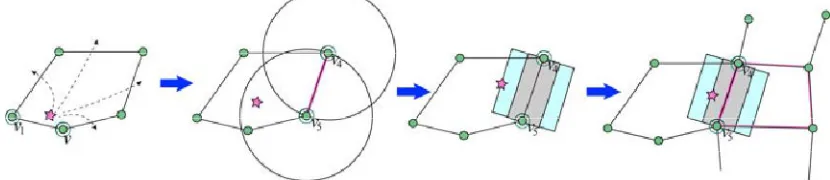
Fig. 4. A straightforward state of affairs of the brink detection method.
In order to find the target specifically, a node ought to satisfy 2 conditions: 1) The node should be in a vigorous polygon;
2) The node should be within the active state once the target passes through the F. Brink on its sensing vary.
The detection chance of the nearest detector to a target all depends on the length of the brink associated an intersection of the sensors’ sensing vary. Because the brink lies on the X-axis, and contains a length of D, the various random values of Intersecting nodes ought to be in a very vary of (_D=2) to (D/2). Thus, the derivation within the on top of will be even simply.
IV.TRACKINGALGORITHMS
While researching this subject it became apparent that they're too many sorts of following algorithms to say and analyze among the scope of 1 paper. to stay this paper manageable, this paper is proscribed to discussing those following algorithms that square measure most typically used at now in time.
a. Straightforward Triangulation:
This formula is given in this it's a very straightforward style and implementation and is a perfect formula to use because the foundation for explaining different additional complicated following algorithms. As expressed higher than, the complete goal of this formula as given by Samar R. Das in [1] is to produce {a straight forward |an easy straightforward} formula that uses simple computation so as to discover AN object, calculate its current location, predict wherever it's headed and inform those nodes close to the expected next location of the item.
This formula initial assumes that every one node within the network square measure localized to a typical indicator and might discover and estimate the gap to target victimization signal strength. Once a node detects AN object among its vary it broadcasts a Target Detected message. This message contains the placement of the sensing element node and therefore the distance to the target. All nodes that hear this message store its information in their native memory. Once a node that has detected the target hears 2 different Target Detected messages from 2 different nodes it performs triangulation on the 3 coordinates to calculate the placement of the target. (Note that this implies that over one node could perform this calculation for a similar target at a similar time.)
ISSN(Online): 2320-9801
ISSN (Print): 2320-9798
International Journal of Innovative Research in Computer
and Communication Engineering
(An ISO 3297: 2007 Certified Organization)
Vol. 3, Issue 8, August 2015
to alert them that the target is headed towards them. These fresh awoken nodes then track the item because it enters their space and repeat the Target Detected and Warning message causing method.
b. Clusters:
The cluster target following formula was wide mentioned through several analysis papers. the fundamental plan of target following victimization clusters is mentioned, followed by an outline of the variances in every of the various cluster formula analysis papers.
The basic formula for following object victimization clusters is as follows:
Some (or all) of the nodes during a cluster discover the item and report their information to a cluster head.
Note that a cluster solely has one cluster head node.
The cluster head node then uses all the target detection data from the sensing element nodes to estimate the
target’s location.
The cluster head then uses the calculated target location and past locations of the target to predict succeeding
location of the target.
Those sensors round the foretold location square measure then woken up to make a brand new cluster (if not
already in one) to discover the target.
When the target is detected during this new cluster, the previous cluster’s nodes square measure all place into
a sleep state. This new cluster then continues the cluster following formula.
c. Hierarchical Super nodes
This formula deviates from the fundamental formula in this the cluster heads (called super nodes) have a better communication vary and additional machine power [6]. These “super nodes” square measure distributed throughout the network and therefore the otherwise traditional nodes square measure appointed to super nodes. Clusters aren't dynamically generated during this formula. Curiously enough, super nodes do share target location data among one another, whereas regular sensing element nodes don't.
d. Dynamic agglomeration
Like the super node formula implementation this formula additionally assumes that cluster head nodes have additional power than traditional sensing element nodes. However, sensing element nodes aren't appointed to clusters during this formula. Instead, they're invited to hitch a cluster by the cluster head. The cluster head will this by broadcasting a be part of message that features the time and signature of the target the cluster head detected. Those sensing element nodes that have keep information that matches {the information the info |the information} within the broadcast message answer the published by causing their captured data to the cluster head node. Apparently, the cluster head solely waits for a particular range of replies and once that range of replies has been received the cluster head calculates the target’s location. Also, not like the super node formula, this formula solely has one active cluster head at a time. In different words, cluster heads do no work along.
e. Predicate agglomeration
This formula differs even afar from the previous 2 in this all nodes within the network square measure a similar. Each node has the potential to become a cluster head [8]. Cluster heads square measure chosen by all nodes among the world of a detected target “electing” to become the pinnacle by broadcasting their intent to become a cluster head. The node with the height sensing element reading is chosen because the cluster head. Once cluster heads square measure chosen, the remaining nodes selected that cluster to hitch by running a choice predicate on their captured sensing element information and therefore the information of their neighbors.
f. Cell Collaboration
ISSN(Online): 2320-9801
ISSN (Print): 2320-9798
International Journal of Innovative Research in Computer
and Communication Engineering
(An ISO 3297: 2007 Certified Organization)
Vol. 3, Issue 8, August 2015
g. stock-still Tree
Related to the clusters following formula is that the plan of the stock-still tree following formula. This formula differs somewhat in this rather than having multiple cluster heads, there's only 1 head node and it's stated because the root. The basis node is that the node that's highest to the target. Once a brand new target location is foretold, if there's another node that's nearer thereto position than the present root then that new node becomes the basis. Other
Nodes round the root work along to make a tree within which their detected information is collected and passed up through the tree (children to parents) till all information reaches the basis. Once the basis receives all the information it calculates the target position and predicts the new target position as mention within the basic target following formula. The tree itself is reconfigured on each root amendment. Once a root amendment happens a “reconfigure” message is broadcast containing the placement of the new root.
Once a node detects the “reconfigure” message it detaches itself from the recent tree and attaches itself to the new tree by recognizing its neighbor node that's highest to the new root node as its new parent. New information is then collected and passed up the tree for the new root to use.
h. Particle Filtering:
The basic plan behind a particle filtering following formula is that various object state descriptions square measure saved that contain information necessary to calculate a target’s position at a particular time. These state descriptions square measure stated as particles and every particle has its own weight. The burden of a particle determines what quantity the information it contains can contribute to the placement estimation of AN object. Once new particles square measure created the weights of the pre-existing particles square measure adjusted then all of the particles square measure accustomed calculates a brand new target location. Eventually, particles with weights that square measure below a particular threshold square measure eliminated as square measure duplicate particles.Some of the particles filtering algorithms do disagree little. Certain algorithms have all the particles keep during a central node and this node wills all the target location process. Different algorithms distribute the keep particles across the network nodes.
i. decentralized Hypothesis
ISSN(Online): 2320-9801
ISSN (Print): 2320-9798
International Journal of Innovative Research in Computer
and Communication Engineering
(An ISO 3297: 2007 Certified Organization)
Vol. 3, Issue 8, August 2015
encompassing nodes and that they every store it. If an occasion happens at these nodes that have associated with a keep hypothesis, then the hypothesis is updated and broadcast. This method continues till the hypothesis satisfies some pre-set detection criteria. Once this happens the hypothesis is reported as a target detection report. Note that hypotheses older than some set time t square measure discarded as square measure duplicate hypothesis.
Fig:three Experimental following performance:meanTEF
Fig:four Experimental following performance: mean TAR achieved.
V. CONCLUSION
The main practicality of a police investigation wireless sensing element network is to trace AN unauthorized target during a field. The challenge is to see a way to understand the target during a WSN with efficiency. We have a tendency to plan a novel plan to attain a WSN system for police work movements of a target victimization plane figure (face) following that doesn't adopt any prediction technique. Analysis results incontestable that the planned following framework will estimate a target’s positioning space, reach following ability with high accuracy, and scale back the energy price of WSNs. From the framework, 2 facts is highlighted emphatically: 1) the target is often detected within a plane figure by means that of a brink detection, and 2) it's strong to sensing element node failures and target localization errors.
Two attention-grabbing issues, that we have a tendency to square measure presently investigation, square measure as follows: 1) the performance of variable brink lengths of the plane figure versus adjustable transmission power levels during a WSN for target detection and its energy price within the WSNs; 2) the impact of the target’s dynamic movements, brink detection, and period of time plane figure forwarding in target following. additional work proposes scientific theory galvanized Mobile Object housings System in Wireless sensing element Network
REFERENCES
1. O. Kaltiokallio, M. Bocca, and L.M. Eriksson, “Distributed RSSI process for Intrusion Detection in Indoor Environments,” Proc. Ninth ACM/IEEE Int’l Conf. scientific discipline in sensing element Networks (IPSN), pp. 404-405, 2010.
2. Y. Wang, M. Vuran, and S. Goddard, “Analysis of Event Detection Delay in Wireless sensing element Networks,” Proc. IEEE INFOCOM, pp. 1296-1304, 2011. 3. Z. Zhong, T. Zhu, D. Wang, and T. He, “Tracking with Unreliable Node Sequence,” Proc. IEEE INFOCOM, pp. 1215-1223, 2009.
4. W. Zhang and G. Cao, “Dynamic Convoy Tree-Based Collaboration for Target following in sensing element Networks,” IEEE Trans. Wireless Comm., vol. 3, no. 5, Sept. 2004.
5. Z. Wang, W. Lou, Z. Wang, J. Ma, and H. Chen, “A Novel quality Management theme for Target following in Cluster-Based sensing element Networks,” Proc. Sixth IEEE Int’l Conf. Distributed Computing in sensing element Systems (DCOSS), pp. 172-186, 2010.
6. L.M. Kaplan, “Global Node choice for Localization during a Distributed sensing element Network,” IEEE Trans. part and Electronic Systems, vol. 42, no. 1, pp. 113-135, Jan. 2006.
7. T. He, P. Vicaire, T. Yan, L. Luo, L. Gu, G. Zhou, R. Stoleru, Q. Cao, J. Stankovic, and T. Abdelzaher, “Achieving period of time Target following victimisation Wireless sensing element Networks,” Proc. twelfth IEEE period of time and Embedded Technology and Applications Symp. (RTAS), pp. 37-48, 2006.
8. M. Waelchli, M. Scheidegger, and T. Braun, “Intensity-Based Event Localization in Wireless sensing element Networks,” Proc. Conf. Int’l Federation for scientific discipline Wireless On-Demand Network Systems and Services (IFIP WONS), pp. 41-49, 2006.
9. Y. Zhou, J. Li, and D. Wang, “Posterior Cramer-Rao Lower Bounds for Target following in sensing element Networks with amount Range-Only Measurements,” IEEE Signal process Letters, vol. 17, no. 2, pp. 377-388, Feb. 2010.