MEA
Shohei 1 Kajima 2 Chubu ABSTRA For agin cannot b applicab the focus Elastic w thickness directly mINTROD
Steel pla concrete strength suitable are sever
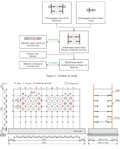
For agin inspectio of the in the conc removing impact p the conc are prom The aim impact p for aging EXPER Outline o This stud specimen compare
ASURING
CONCR
i Sawada1, Y
a Corporation Electric Pow
ACT
ng assessmen be assessed by
ility of non-s on elanon-stic w wave velocity
s) were mea measured va
DUCTION
ate reinforce connected b
and ductilit for pre-fabri ral examples
ng assessmen on since the c nternal concre crete, such a
g the steel p pulse method rete, which a mising method
of this study pulse method g assessment
RIMENTAL
of study and
dy is outline ns were estim ed with thos
G METH
RETE OF
Yoshikazu Ic
n, Japan wer Co., Inc.,
nt of steel pla y visual insp destructive m wave velocit y and elastic asured by u
lues for conc
ed concrete ( by studs and ty, they ena ication. In Ja
of their appl
nt of SC stru concrete is sa ete, testing o as strength an plate and con ds enable non are regarded ds for evalua
y is to evalua ds with the fo of SC struct
DETAILS
d specimen
d in Figure 1 mated based
e of concret
OD OF E
STEEL P
ST
chikawa1, Yo and
Japan
ate reinforced pection since
methods such ty and elastic c modulus of
ltrasonic and crete cores ex
(SC) structur d/or tie-bars. able reduced
apan, structu lication to re
uctures, the andwiched by
f drilled core nd stiffness, ncrete, thus a n-destructive
as potential ating the soun
ate the applic ocus on elast tures.
1. Elastic w on results ob te cores ext
ELASTIC
PLATE R
TRUCTUR
oshiyuki Tak d Yoshito Um
d concrete ( the concrete h as ultrason c modulus o f internal con d impact pu xtracted from
res are comp . In additio
construction ural design m al nuclear fac
state of the y steel plates es of concret and is the and causing estimation o
indices for e ndness of SC
cability of no tic wave velo
wave velocity btained from tracted from
WAVE V
REINFOR
RES
kahashi1, Os meki2
SC) structure is sandwich nic and impac
f concrete as ncrete of SC ulse methods m SC wall spe
posite struct on to good a n periods fo methods have
cilities.
internal con s. Among oth te directly pr
most reliabl damage to s of elastic wa evaluating th C structures.
on-destructiv ocity and ela
and elastic m m ultrasonic a
the same s
VELOCIT
RCED CO
samu Konta
es, the state ed by steel p ct pulse meth s indices of a C wall specim s and results ecimens.
tures compos aseismic perf or nuclear fa e already bee
ncrete cannot her methods rovides the m e method. H structure. H
ave velocity he state of the
ve techniques astic modulus
modulus of i and impact p specimens in
TY OF IN
ONCRETE
ani1, Hiroyuk
of the intern plates. In this
hods were st aging of SC mens (1.5 m s were comp
sed of steel formance su acilities sinc en established
t be assessed for estimatin mechanical pr
However, th
However, ultr
and elastic m e internal con
s such as ultr s of concrete
internal conc pulse method n order to v
NSIDE
E
ki Wada2
al concrete s study, the tudied with structures. and 0.7 m pared with
plates and ch as high ce they are d and there
d by visual ng the state roperties of his requires rasonic and modulus of ncrete, and
rasonic and e as indices
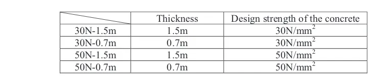
proposed methods. The specimens’ dimensions are shown in Figure 2. The specimens were SC structures sandwiched by steel plates with a thickness of 9mm. They were 2500mm long and 1500mm high. There were two thicknesses: 700mm and 1500mm. The design strengths of the concrete, which were ready-mixed concrete (moderate-heat Portland cement, water cement ratios of 60% and 45%), were
30N/mm2 and 50N/mm2. Four specimens were prepared, as shown in Table 1. Studs (22mm diameter
and 550mm length) and tie-bars were placed at intervals of 200mm.
Figure 1. Outline of study
Figure 2. Dimension of specimen and measurement points 䐤Elastic modulus of
concrete core
Comparing
䐟Propagation time of SC specimen
䐠Propagation time of steel + stud
䐡Estimated elastic wave velocity of internal concrete 䐢Elastic wave velocity of
concrete core
Poisson ratio Density
䐣Estimated elastic modulus based on theory of
elasticity
Comparing
2
5
0
200
U
M L
U
M L
1
5
0
0
2
0
0
2
5
0
2
0
0
2
0
0
2
0
0
2
0
0
2
0
0
2
0
0
1
0
0
!100
250
200
2900 2500
200 200 200 200 200 200 200 200 200 200 250
Stud
1
2
3
4
a b c d e
U
M L 1M
U
M L 1Y
Measurement point Coring point
6
0
6
0
2Y 3Y
f g h i j k
Basement Tie-bar
Stud
Tie-bar Steel plate
200 1500 or 700 200
Table 1: List of specimens
Thickness Design strength of the concrete
30N-1.5m 1.5m 30N/mm2
30N-0.7m 0.7m 30N/mm2
50N-1.5m 1.5m 50N/mm2
50N-0.7m 0.7m 50N/mm2
Measurements
The elastic waves of SC specimens were measured by two non-destructive methods: ultrasonic and impact pulse methods. In the ultrasonic method, elastic waves are generated by an oscillator using the range of over 20kHz to propagate through the concrete and are measured by a receiver. In the impact pulse method, elastic waves are generated by impacting the steel plate surface with an impactor (rigid ball) and are measured by a receiver. When measuring elastic waves through internal concrete of an SC structure, it was reported that elastic waves could not be precisely measured if there was the narrow gap between the steel plate and the concrete, even if the concrete was sufficiently consolidated [1]. In this study, to obtain stable data, probes were placed on the position of a stud, where concrete was better consolidated. Both measurements, ultrasonic and impact pulse, were conducted four times, one month, one year, two years and three years after casting. After the measurements, concrete cores were extracted from the specimens based on JIS A1107 [2]. Measuring stud points are shown in Figure 2 as red crosses, which are positioned around the corresponding coring points. Pairs of incoming and outgoing pulses are shown in Table 2. Elastic waves of studs welded onto steel plate without concrete were measured before concrete casting. Elastic waves of concrete cylinders extracted from specimens by coring were also measured as concrete elastic waves alone.
Since the measured elastic waves included not only concrete effect but also steel plate and stud effects, the estimated elastic wave velocity of the internal concrete was calculated by subtracting the propagation time of the stud from total propagation time of the SC specimen (Figure 3).
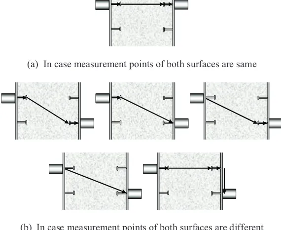
If the measurement position on the front surface is not the same as that on the back surface, the passage of the elastic wave is different depending on pairs of measurement positions. In this case, there are five passages, as shown in Figure 4. The actual passage depends on the combination of specimen thickness and measuring positions. Actual passage is estimated to be the passage indicating the slowest elastic wave velocity.
Table 2: Pair of measurement positions (example for one month)
In case of same measurement point In case of different measurement point
Both surface Front surface Back surface
a2 b1 b2
a3 b2 b3
b1 b3 b4
b2 b1 b3
b3 b2 b4
b4 b1 b4
Figure 3. Calculation method of elastic wave velocity of internal concrete of SC structure
(a) In case measurement points of both surfaces are same
(b) In case measurement points of both surfaces are different
Figure 4. Potential propagation pass of elastic wave
l
t(m), tt(s)
lc(m), tc(s)
ls(m), ts(s) ls(m), ts(s)
Concrete Steel + stud
Steel + stud
Length of concrete lc(m)䠙lt䠉2䡡ls
Estimated propagation time of concrete tc(s)䠙tt䠉2䡡ts
Estimated elastic wave velocity of concrete V
c(m/s)䠙lc䠋tc
l
t䠖Length of SC specimen (m)
ls䠖Length of steel + stud (m)
tt䠖Propagation time of SC specimen (s)
t
RESULTS AND DISCCUSSION
Elastic wave velocities of concrete
Figures 5 and 6 compare the estimated elastic wave velocities calculated from the results of ultrasonic and impact pulse methods and the elastic wave velocities of the cores extracted from the SC specimens. For both methods, the estimated elastic wave velocities are smaller than concrete core velocities, but an increasing tendency depending on water cement ratio and material age is captured. The results for the 0.7m-thick specimens vary more widely than those of the 1.5m-thick specimens since presumably the proportion of the concrete part of propagation time was small compared to total time.
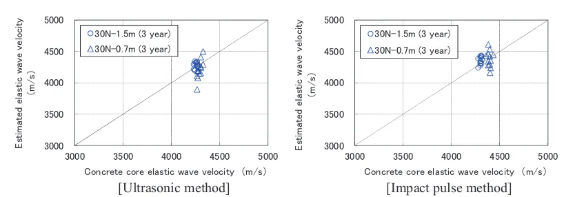
Estimated elastic wave velocities obtained from the impact pulse method are smaller and more scattered than those obtained from the ultrasonic method. However, the elastic wave velocity of the core specimens obtained from both methods are almost identical. When the elastic wave velocities of the internal concrete are estimated, the propagation times for a stud only are used, but the propagation times obtained from the ultrasonic and impact pulse methods for a stud surrounded by concrete may be different. For proof of the above assumption, the propagation time for a stud surrounded by concrete was measured and compared with that for a stud only. Table 3 shows the results. In the ultrasonic method, the propagation time for the stud surrounded by concrete is about 10% smaller than that for the stud only. In the impact pulse method, the difference is about 30%. It is confirmed that the propagation time for a stud is reduced by the existence of concrete. Figure 7 shows the elastic wave velocities for 3 years of material age estimated from the propagation time of a stud surrounded by concrete. In both methods, re-estimated values show good coincidence with that of the core specimens. The propagation time for a stud surrounded by concrete is more suitable for calculation of internal concrete elastic wave velocity of an SC structure.
Figure 5. Comparison between estimated elastic wave velocities and core specimen elastic wave velocities [Ultrasonic method]
㻟㻜㻜㻜 㻟㻡㻜㻜 㻠㻜㻜㻜 㻠㻡㻜㻜 㻡㻜㻜㻜
㻟㻜㻜㻜 㻟㻡㻜㻜 㻠㻜㻜㻜 㻠㻡㻜㻜 㻡㻜㻜㻜
㻱
㼟㼠
㼕㼙
㼍㼠
㼑
㼐㻌
㼑
㼘㼍
㼟㼠
㼕㼏
㻌㼣
㼍㼢
㼑
㻌㼢
㼑
㼘㼛
㼏
㼕㼠
㼥
䠄㼙㻛㼟
䠅
㻯㼛㼚㼏㼞㼑㼠㼑㻌㼏㼛㼞㼑㻌㼑㼘㼍㼟㼠㼕㼏㻌㼣㼍㼢㼑㻌㼢㼑㼘㼛㼏㼕㼠㼥 䠄㼙㻛㼟䠅 㻟㻜㻺㻙㻝㻚㻡㼙㻌㻔㻝㻌㼙㼛㼚㼠㼔㻕
㻟㻜㻺㻙㻜㻚㻣㼙㻌㻔㻝㻌㼙㼛㼚㼠㼔㻕 㻡㻜㻺㻙㻝㻚㻡㼙㻌㻔㻝㻌㼙㼛㼚㼠㼔㻕 㻡㻜㻺㻙㻜㻚㻣㼙㻌㻔㻝㻌㼙㼛㼚㼠㼔㻕
㻟㻜㻜㻜 㻟㻡㻜㻜 㻠㻜㻜㻜 㻠㻡㻜㻜 㻡㻜㻜㻜
㻟㻜㻜㻜 㻟㻡㻜㻜 㻠㻜㻜㻜 㻠㻡㻜㻜 㻡㻜㻜㻜
㻱
㼟㼠
㼕㼙
㼍㼠
㼑
㼐㻌
㼑
㼘㼍
㼟㼠
㼕㼏
㻌㼣
㼍㼢
㼑
㻌㼢
㼑
㼘㼛
㼏
㼕㼠
㼥
䠄㼙
㻛㼟䠅
㻯㼛㼚㼏㼞㼑㼠㼑㻌㼏㼛㼞㼑㻌㼑㼘㼍㼟㼠㼕㼏㻌㼣㼍㼢㼑㻌㼢㼑㼘㼛㼏㼕㼠㼥 䠄㼙㻛㼟䠅 㻟㻜㻺㻙㻝㻚㻡㼙㻌㻔㻝㻌㼥㼑㼍㼞㻕
㻟㻜㻺㻙㻜㻚㻣㼙㻌㻔㻝㻌㼥㼑㼍㼞㻕 㻡㻜㻺㻙㻝㻚㻡㼙㻌㻔㻝㻌㼥㼑㼍㼞㻕 㻡㻜㻺㻙㻜㻚㻣㼙㻌㻔㻝㻌㼥㼑㼍㼞㻕
㻟㻜㻜㻜 㻟㻡㻜㻜 㻠㻜㻜㻜 㻠㻡㻜㻜 㻡㻜㻜㻜
㻟㻜㻜㻜 㻟㻡㻜㻜 㻠㻜㻜㻜 㻠㻡㻜㻜 㻡㻜㻜㻜
㻱
㼟㼠
㼕㼙
㼍㼠
㼑
㼐㻌
㼑
㼘㼍
㼟㼠
㼕㼏
㻌㼣
㼍㼢
㼑
㻌㼢
㼑
㼘㼛
㼏
㼕㼠
㼥
䠄㼙
㻛㼟䠅
㻯㼛㼚㼏㼞㼑㼠㼑㻌㼏㼛㼞㼑㻌㼑㼘㼍㼟㼠㼕㼏㻌㼣㼍㼢㼑㻌㼢㼑㼘㼛㼏㼕㼠㼥 䠄㼙㻛㼟䠅 㻟㻜㻺㻙㻝㻚㻡㼙㻌㻔㻞㻌㼥㼑㼍㼞㻕
㻟㻜㻺㻙㻜㻚㻣㼙㻌㻔㻞㻌㼥㼑㼍㼞㻕 㻡㻜㻺㻙㻝㻚㻡㼙㻌㻔㻞㻌㼥㼑㼍㼞㻕 㻡㻜㻺㻙㻜㻚㻣㼙㻌㻔㻞㻌㼥㼑㼍㼞㻕
㻟㻜㻜㻜 㻟㻡㻜㻜 㻠㻜㻜㻜 㻠㻡㻜㻜 㻡㻜㻜㻜
㻟㻜㻜㻜 㻟㻡㻜㻜 㻠㻜㻜㻜 㻠㻡㻜㻜 㻡㻜㻜㻜
㻱
㼟㼠
㼕㼙
㼍㼠
㼑
㼐㻌
㼑
㼘㼍
㼟㼠
㼕㼏
㻌㼣
㼍㼢
㼑
㻌㼢
㼑
㼘㼛
㼏
㼕㼠
㼥
䠄㼙
㻛㼟䠅
㻯㼛㼚㼏㼞㼑㼠㼑㻌㼏㼛㼞㼑㻌㼑㼘㼍㼟㼠㼕㼏㻌㼣㼍㼢㼑㻌㼢㼑㼘㼛㼏㼕㼠㼥 䠄㼙㻛㼟䠅 㻟㻜㻺㻙㻝㻚㻡㼙㻌㻔㻟㻌㼥㼑㼍㼞㻕
Figure 6. Comparison between estimated elastic wave velocities and core specimen elastic wave velocities [Impact pulse method]
Table 3: Comparison of elastic wave velocity of steel + stud
Values in brackets are proportion of (2) to (1).
㻟㻜㻜㻜 㻟㻡㻜㻜 㻠㻜㻜㻜 㻠㻡㻜㻜 㻡㻜㻜㻜
㻟㻜㻜㻜 㻟㻡㻜㻜 㻠㻜㻜㻜 㻠㻡㻜㻜 㻡㻜㻜㻜
㻱
㼟㼠
㼕㼙
㼍㼠
㼑
㼐㻌
㼑
㼘㼍
㼟㼠
㼕㼏
㻌㼣
㼍㼢
㼑
㻌㼢
㼑
㼘㼛
㼏
㼕㼠
㼥
䠄
㼙
㻛
㼟䠅
㻯㼛㼚㼏㼞㼑㼠㼑㻌㼏㼛㼞㼑㻌㼑㼘㼍㼟㼠㼕㼏㻌㼣㼍㼢㼑㻌㼢㼑㼘㼛㼏㼕㼠㼥 䠄㼙㻛㼟䠅 㻟㻜㻺㻙㻝㻚㻡㼙㻌㻔㻝㻌㼙㼛㼚㼠㼔㻕
㻟㻜㻺㻙㻜㻚㻣㼙㻌㻔㻝㻌㼙㼛㼚㼠㼔㻕 㻡㻜㻺㻙㻝㻚㻡㼙㻌㻔㻝㻌㼙㼛㼚㼠㼔㻕 㻡㻜㻺㻙㻜㻚㻣㼙㻌㻔㻝㻌㼙㼛㼚㼠㼔㻕
㻟㻜㻜㻜 㻟㻡㻜㻜 㻠㻜㻜㻜 㻠㻡㻜㻜 㻡㻜㻜㻜
㻟㻜㻜㻜 㻟㻡㻜㻜 㻠㻜㻜㻜 㻠㻡㻜㻜 㻡㻜㻜㻜
㻱
㼟㼠
㼕㼙
㼍㼠
㼑
㼐㻌
㼑
㼘㼍
㼟㼠
㼕㼏
㻌㼣
㼍㼢
㼑
㻌㼢
㼑
㼘㼛
㼏
㼕㼠
㼥
䠄
㼙
㻛
㼟䠅
㻯㼛㼚㼏㼞㼑㼠㼑㻌㼏㼛㼞㼑㻌㼑㼘㼍㼟㼠㼕㼏㻌㼣㼍㼢㼑㻌㼢㼑㼘㼛㼏㼕㼠㼥 䠄㼙㻛㼟䠅 㻟㻜㻺㻙㻝㻚㻡㼙㻌㻔㻝㻌㼥㼑㼍㼞㻕
㻟㻜㻺㻙㻜㻚㻣㼙㻌㻔㻝㻌㼥㼑㼍㼞㻕 㻡㻜㻺㻙㻝㻚㻡㼙㻌㻔㻝㻌㼥㼑㼍㼞㻕 㻡㻜㻺㻙㻜㻚㻣㼙㻌㻔㻝㻌㼥㼑㼍㼞㻕
㻟㻜㻜㻜 㻟㻡㻜㻜 㻠㻜㻜㻜 㻠㻡㻜㻜 㻡㻜㻜㻜
㻟㻜㻜㻜 㻟㻡㻜㻜 㻠㻜㻜㻜 㻠㻡㻜㻜 㻡㻜㻜㻜
㻱
㼟㼠
㼕㼙
㼍㼠
㼑
㼐㻌
㼑
㼘㼍
㼟㼠
㼕㼏
㻌㼣
㼍㼢
㼑
㻌㼢
㼑
㼘㼛
㼏
㼕㼠
㼥
䠄
㼙
㻛
㼟䠅
㻯㼛㼚㼏㼞㼑㼠㼑㻌㼏㼛㼞㼑㻌㼑㼘㼍㼟㼠㼕㼏㻌㼣㼍㼢㼑㻌㼢㼑㼘㼛㼏㼕㼠㼥 䠄㼙㻛㼟䠅 㻟㻜㻺㻙㻝㻚㻡㼙㻌㻔㻞㻌㼥㼑㼍㼞㻕
㻟㻜㻺㻙㻜㻚㻣㼙㻌㻔㻞㻌㼥㼑㼍㼞㻕 㻡㻜㻺㻙㻝㻚㻡㼙㻌㻔㻞㻌㼥㼑㼍㼞㻕 㻡㻜㻺㻙㻜㻚㻣㼙㻌㻔㻞㻌㼥㼑㼍㼞㻕
㻟㻜㻜㻜 㻟㻡㻜㻜 㻠㻜㻜㻜 㻠㻡㻜㻜 㻡㻜㻜㻜
㻟㻜㻜㻜 㻟㻡㻜㻜 㻠㻜㻜㻜 㻠㻡㻜㻜 㻡㻜㻜㻜
㻱
㼟㼠
㼕㼙
㼍㼠
㼑
㼐㻌
㼑
㼘㼍
㼟㼠
㼕㼏
㻌㼣
㼍㼢
㼑
㻌㼢
㼑
㼘㼛
㼏
㼕㼠
㼥
䠄
㼙
㻛
㼟䠅
㻯㼛㼚㼏㼞㼑㼠㼑㻌㼏㼛㼞㼑㻌㼑㼘㼍㼟㼠㼕㼏㻌㼣㼍㼢㼑㻌㼢㼑㼘㼛㼏㼕㼠㼥 䠄㼙㻛㼟䠅 㻟㻜㻺㻙㻝㻚㻡㼙㻌㻔㻟㻌㼥㼑㼍㼞㻕
㻟㻜㻺㻙㻜㻚㻣㼙㻌㻔㻟㻌㼥㼑㼍㼞㻕 㻡㻜㻺㻙㻝㻚㻡㼙㻌㻔㻟㻌㼥㼑㼍㼞㻕 㻡㻜㻺㻙㻜㻚㻣㼙㻌㻔㻟㻌㼥㼑㼍㼞㻕
(1) Stud + steel only
Propagation time (!s) 41.4 47.1 [1.14]
Length of steel + stud (mm) 229 229 [1.00]
Elastic wave velocity (m/s) 5531 4862 [0.88]
Propagation time (!s) 30.7 33.3 [1.08]
Length of steel + stud (mm) 166 166 [1.00]
Elastic wave velocity (m/s) 5407 4985 [0.92]
Propagation time (!s) 35.5 49.0 [1.38]
Length of steel + stud (mm) 229 229 [1.00]
Elastic wave velocity (m/s) 6451 4673 [0.72]
Propagation time (!s) 24.4 35.4 [1.45]
Length of steel + stud (mm) 166 166 [1.00]
Elastic wave velocity (m/s) 6803 4689 [0.69]
30N-1.5m
(2) Stud + steel surrounded by concrete
Ultrasonic
Method Item
Impact pulse
30N-1.5m
30N-0.7m Name of specimen
[Ultrasonic method] [Impact pulse method]
Figure 7. Comparison with re-estimated elastic wave velocity and elastic wave velocity of concrete core
Elastic modulus of concrete
The elastic modulus of the internal concrete of SC specimens can be calculated by Equation (1) using elastic wave velocities estimated in the previous section.
!
"!
"
c c c
c c
c V
E
#
$
$
$
21 2 1 1
% % &
' 1
where, Ec : Elastic modulus of internal concrete (kN/mm2)
Ȥc : Poisson ratio of concrete (0.2)
Vc : Elastic wave velocity of internal concrete (km/s)
Ȩc : Density of concrete (t/m3)
Figures 8 and 9 compare the elastic moduli estimated from the results of ultrasonic and impact pulse methods and the static modulus of elasticity of cores extracted from SC specimens with a thickness of 1.5m. Only data of the upper part corresponding to position “U” in Figure 1 are plotted, since the elastic modulus of the cores was obtained from only the upper part. For both methods, estimated elastic moduli are larger than the static modulus of elasticity of the concrete cores, but an increasing tendency depending on water cement ratio and material age is captured.
Since the estimated elastic modulus based on elastic wave velocity approximates the dynamic modulus of elasticity, estimated values are larger than the static modulus of elasticity of the concrete cores calculated as the secant modulus at 1/3 compressive strength in the stress-strain curve. Therefore, the dynamic elastic modulus of the concrete core was measured and compared to the estimated elastic modulus calculated from equation (1) using Poisson’s ratio determined dynamically, i.e. 0.24 [3]. The dynamic elastic modulus of the concrete core was obtained from the first resonance frequency of longitudinal vibration of the core, based on JIS A1127 [4]. Figure 10 compares the estimated elastic modulus for 3 years of material age with the dynamic elastic modulus of the concrete core. For both methods, the estimated values are more coincident with the dynamic elastic modulus than the static modulus of the concrete core.
㻟㻜㻜㻜 㻟㻡㻜㻜 㻠㻜㻜㻜 㻠㻡㻜㻜 㻡㻜㻜㻜
㻟㻜㻜㻜 㻟㻡㻜㻜 㻠㻜㻜㻜 㻠㻡㻜㻜 㻡㻜㻜㻜
㻱
㼟㼠
㼕㼙
㼍㼠
㼑
㼐㻌
㼑
㼘㼍
㼟㼠
㼕㼏
㻌㼣
㼍㼢
㼑
㻌㼢
㼑
㼘㼛
㼏
㼕㼠
㼥
䠄
㼙
㻛
㼟䠅
㻯㼛㼚㼏㼞㼑㼠㼑㻌㼏㼛㼞㼑㻌㼑㼘㼍㼟㼠㼕㼏㻌㼣㼍㼢㼑㻌㼢㼑㼘㼛㼏㼕㼠㼥 䠄㼙㻛㼟䠅 㻟㻜㻺㻙㻝㻚㻡㼙㻌㻔㻟㻌㼥㼑㼍㼞㻕
㻟㻜㻺㻙㻜㻚㻣㼙㻌㻔㻟㻌㼥㼑㼍㼞㻕
㻟㻜㻜㻜 㻟㻡㻜㻜 㻠㻜㻜㻜 㻠㻡㻜㻜 㻡㻜㻜㻜
㻟㻜㻜㻜 㻟㻡㻜㻜 㻠㻜㻜㻜 㻠㻡㻜㻜 㻡㻜㻜㻜
㻱
㼟㼠
㼕㼙
㼍㼠
㼑
㼐㻌
㼑
䡈㼍
㼟㼠
㼕㼏
㻌㼣
㼍㼢
㼑
㻌㼢
㼑
㼘㼛
㼏
㼕㼠
㼥
䠄
㼙
㻛
㼟䠅
㻯㼛㼚㼏㼞㼑㼠㼑㻌㼏㼛㼞㼑㻌㼑㼘㼍㼟㼠㼕㼏㻌㼣㼍㼢㼑㻌㼢㼑㼘㼛㼏㼕㼠㼥 䠄㼙㻛㼟䠅 㻟㻜㻺㻙㻝㻚㻡㼙㻌㻔㻟㻌㼥㼑㼍㼞㻕
Figure 8. Comparison between estimated elastic modulus and coring specimen static elastic modulus [Ultrasonic method]
Figure 9. Comparison between estimated elastic modulus and coring specimen static elastic modulus [Impact pulse method]
[Ultrasonic method] [Impact pulse method]
Figure 10. Comparison of estimated elastic modulus and dynamic elastic modulus of concrete core
CONCLUSIONS
The main conclusions of this study may be summarised as follows. From these conclusions, it may be said that two non-destructive methods, ultrasonic and impact pulse methods, are suitable for evaluating the state of internal concrete, such as elastic wave velocity and elastic modulus.
- The elastic wave velocity of internal concrete of an SC structure can be precisely estimated
from the results of ultrasonic and impact pulse methods at the position of a stud.
- The elastic wave velocity and elastic modulus estimated by the proposed methods in this study
are able to capture the increasing tendency depending on water cement ratio and material age.
- The elastic modulus estimated from the results of the ultrasonic and impact pulse methods are
more coincident with the dynamic elastic modulus than the static modulus of a concrete core.
ACKNOWLEDGMENTS
This study was carried out as a part of collaborative research projects funded by Chubu Electric Power Co., Inc., Hokkaido Electric Power Co., Inc., Tohoku Electric Power Co., Inc., Tokyo Electric Power Co., Inc., Hokuriku Electric Power Co., Inc., Kansai Electric Power Co., Inc., Chugoku Electric Power Co., Inc., Shikoku Electric Power Co., Inc., Kyushu Electric Power Co., Inc., The Japan Atomic Power Company, Electric Power Development Co., Ltd. and Japan Nuclear Fuel Limited.
The authors would like to express their sincere gratitude to Professor Emeritus K. Takiguchi, Tokyo Institute of Technology, Dr. H. Kasami, Professor S. Hatanaka, Mie University, Professor I. Kishimoto, Kinki University and Associate Professor I. Maruyama, Nagoya University for their valuable advice.
REFERENCES
[1] Y. Ichikawa et.al., (2010). “Soundness evaluation of SC structures using ultrasonic waves”,
Summaries of technical papers of annual meeting, Architectural Institute of Japan, in Japanese. [2] JIS A1107, (2012). “ Method of sampling and testing for compressive strength of drilled cores of
concrete”, Japanese Industrial Standard.
[3] A.M. Neville, (1995). Properties of Concrete, 4th edition, Prentice Hall.
[4] JIS A1127, (2010). “Methods of test for dynamic modulus of elasticity, rigidity and Poisson's ratio of
concrete by resonance vibration”, Japanese Industrial Standard.
㻜 㻝㻜 㻞㻜 㻟㻜 㻠㻜 㻡㻜
㻜 㻝㻜 㻞㻜 㻟㻜 㻠㻜 㻡㻜
㻱
㼟㼠
㼕㼙
㼍㼠
㼑
㼐㻌
㼑
㼘㼍
㼟㼠
㼕㼏
㻌㼙
㼛
㼐
㼡
㼘㼡
㼟
䠄
㼗㻺
㻛
㼙
㼙
㻞䠅
㻯㼛㼚㼏㼞㼑㼠㼑㻌㼏㼛㼞㼑㻌㼐㼥㼚㼍㼙㼕㼏㻌㼑㼘㼍㼟㼠㼕㼏㻌㼙㼛㼐㼡㼘㼡㼟 䠄㼗㻺㻛㼙㼙㻞䠅
㻟㻜㻺㻙㻝㻚㻡㼙㻌㻔㻟㻌㼥㼑㼍㼞㻕 㻡㻜㻺㻙㻝㻚㻡㼙㻌㻔㻟㻌㼥㼑㼍㼞㻕
㻜 㻝㻜 㻞㻜 㻟㻜 㻠㻜 㻡㻜
㻜 㻝㻜 㻞㻜 㻟㻜 㻠㻜 㻡㻜
㻱
㼟㼠
㼕㼙
㼍㼠
㼑
㼐㻌
㼑
㼘㼍
㼟㼠
㼕㼏
㻌㼙
㼛
㼐
㼡
㼘㼡
㼟
䠄
㼗㻺
㻛
㼙
㼙
㻞䠅
㻯㼛㼚㼏㼞㼑㼠㼑㻌㼏㼛㼞㼑㻌㼐㼥㼚㼍㼙㼕㼏㻌㼑㼘㼍㼟㼠㼕㼏㻌㼙㼛㼐㼡㼘㼡㼟 䠄㼗㻺㻛㼙㼙㻞䠅
![Figure 5. Comparison between estimated elastic wave velocities and core specimen elastic wave velocities [Ultrasonic method]](https://thumb-us.123doks.com/thumbv2/123dok_us/1565285.1192374/5.612.101.512.403.652/figure-comparison-estimated-elastic-velocities-specimen-velocities-ultrasonic.webp)
![Figure 6. Comparison between estimated elastic wave velocities and core specimen elastic wave velocities [Impact pulse method]](https://thumb-us.123doks.com/thumbv2/123dok_us/1565285.1192374/6.612.101.514.101.361/figure-comparison-estimated-elastic-velocities-specimen-elastic-velocities.webp)
![Figure 8. Comparison between estimated elastic modulus and coring specimen static elastic modulus [Ultrasonic method]](https://thumb-us.123doks.com/thumbv2/123dok_us/1565285.1192374/8.612.105.508.401.651/figure-comparison-estimated-elastic-modulus-specimen-elastic-ultrasonic.webp)

