Comparative Analysis of Three Level Inverter
Fed Induction Motor Drive with and Without
DTC Technique
Arya Chandran D.1, Surasmi N.L.2
P.G. Student, Department of Electrical and Electronics Engineering, Mar Baselios College of Engineering and
Technology, Mar Ivanios Vidyanagar, Nalanchira, Thiruvananthapuram, India1
Assistant Professor, Department of Electrical and Electronics Engineering, Ma r Baselios College of Engineering and
Technology, Mar Ivanios Vidyanagar, Nalanchira, Thiruvananthapuram, India 2
ABSTRACT: In this paper, the torque and speed ripple of an Induction Motor (IM) fed by a three level Neutral Point
clamped Inverter (NPC) is compared with and without Direct Torque Control (DTC). The main disadvantage of conventional DTC is variable switching frequency and fast sampling time because of hysteresis based control loops. To eliminate this disadvantage, a basic control technique called direct toque control with space vector modulation has been developed here. The modified DTC uses the PI controllers and a space vector modulator (SVM) technique instead of hysteresis controller. By this method fixed switching frequency is achieved which reduces the switching losses as well as torque and speed ripple.
KEYWORDS:Induction Motor, Direct Torque Control, Multi level Inverter, Space vector Modulation.
I. INTRODUCTION
Now a days most of the electric drives used in our industry are adjustable speed drives. An Induction Motor is the most modest electrical machine from constructional point of view because of robustness, cheapness, high speed operation and less maintenance requirement.[1] Induction Machine always run at a speed lower than synchronous speed. For industrial sectors involving IM drives, speed and torque control is a critical issue especially in dynamic condition. Induction Motor can be controlled through scalar and vector control techniques. In this project a vector control technique called Direct Torque Control is done. The main advantages of the DTC technique are absence of co-ordinate transform, absence of voltage modulator block, minimal torque response time[2]. But DTC technique has many disadvantages also. That is, it require fast sampling time and variable switching frequency, because of hysteresis based control loop. In order to eliminate these disadvantages, DTC with space vector modulation has been developed here. Torque and current ripple are occurred in the conventional DTC. Reason of undesired torque and current ripple is less number of voltage vectors applied to the motor controlled by the conventional DTC technique [3]. SVMDTC is a technique to reduce ripple. It allows achieving fixed switching frequency, which reduces switching losses and speed and torque ripples.
Paper is organized as follows. Section II describes the three level neutral point clamped inverter with space vector modulation. DTC technique is explained in section III. Section IV presents the simulations and their results. Section V presents conclusion.
II. RELATEDWORK
Three Level neutral point clamped inverter
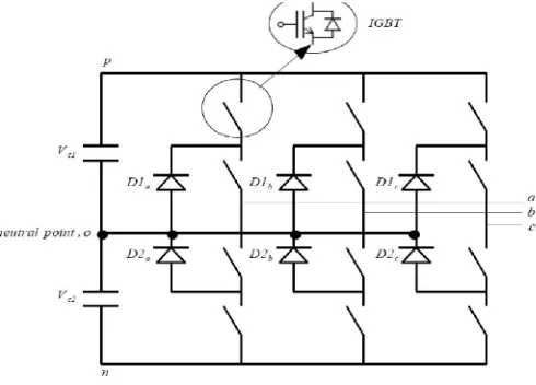
A 3 level neutral point clamped inverter is shown in fig 1. A three level neutral point clamped inverter contain 12 switching devices and two capacitors are connected in series.
The point between these capacitors is the
DC-voltage neutral point. Each phase leg consists of 4 series-connected switching devices and two clamping
diodes.
Fig 1: Three level neutral point clamped inverter
The clamping diode is to clamp the six middle switches potential to the DC-link point at zero. Specific combination of twelve switches gives the three level output voltage. The four switches in one phase leg can only be turned on two times and so be connected to the DC-link points p, o, n
Table 1 : Switching States
on off off
on on off
off on on
off off on
Vdc 0 -Vdc
Switching states P O N
Fig 2: Vector diagram
Figure 2 shows the vector diagram of a three level neutral point clamped inverter. For a 3 level three phase inverter has 27 switching states is shown here. It generate 5 levels of output. ie, 2Vdc, Vdc, 0, -Vdc, -2Vdc.
III.PROPOSEDDTCTECHNIQUE
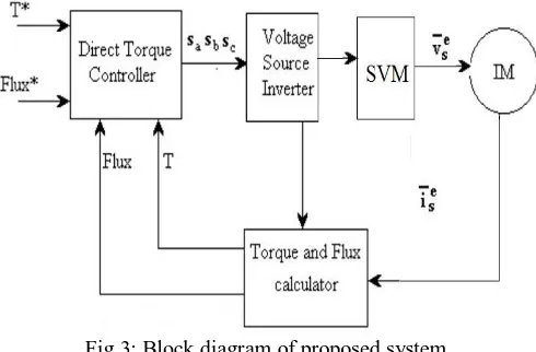
Direct Torque Control is a method to control the utilizing torque and flux of motor. Basic DTC consists of two comparator, switching table, voltage source inverter, torque and flux estimator block and an Induction Motor.
Fig 3: Block diagram of proposed system
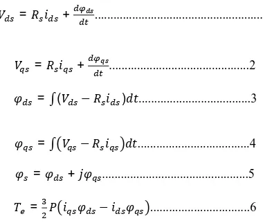
error signal is processed with the help of PI controller. The electromagnetic torque and flux are calculated from motor inputs like stator voltage and current. The controller initiates with the direct selection of stator voltage vectors according to torque and flux error. These errors are the difference between references of torque and stator flux linkage with their actual value. Here, flux and torque estimating equations are used to determine the actual value of the flux linkage and torque. The torque and flux equations are given below:
= + ...1
= + ...2
=∫( − ) ...3
=∫ − ...4
= + ...5
= − ...6
By using PI controllers and numeric calculations, create the voltage corresponding to dq stationary reference frame. This quantities are transformed into abc frame and is used for creating reference voltage. Torque angle is used for sector selection. The reference voltage which compensate the error is created which is used for modulating with the carrier and the switching signals are generated that is given to the inverter, then the inverter output is given to IM. Appropriate space voltage vector can be generated with SVM and fixed switching frequency can be achieved. Thus torque and speed ripple get reduced. The main features of DTC technique is decoupled control of torque and flux, current regulators and co-ordinate transformation are not required, mechanical transducers are absent, it reduces parameter sensitivity. DTC is a simple control scheme and have low computational time.
IV.EXPERIMENTAL RESULTS
The proposed system is simulated using Matlab and the results are verified. The parameters of Induction Motor drive are shown in Table 2
Table 2: Induction motor parameters
Parameters Value
Stator resistance 0.19
Rotor resistance 0.39
Mutual inductance 4mH
No: of poles 4
Frequency 50
inertia 0.0226
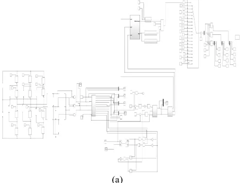
Figure 4 shows the three level inverter fed induction motor without DTC.
Fig 4(a) shows the MATLAB simulink model of three level neutral point clamped inverter fed with Induction Motor.
(a)
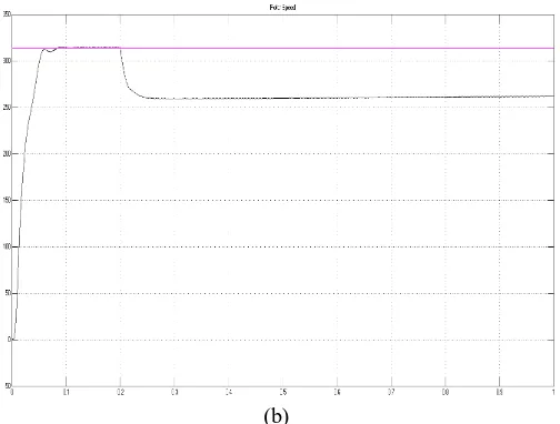
. The speed of Induction Motor is shown in fig 4(b). Here the speed ripple is obtained as 2% without DTC technique.
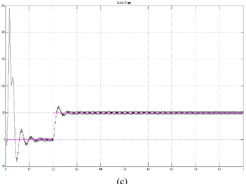
Fig 4(c) shows the torque of an induction motor. Here the torque ripple is obtained as 34%.
(c)
Figure 5 shows the three level inverter fed induction motor with DTC. Fig 5(a) shows the MATLAB simulink model of three level neutral point clamped inverter fed Induction Motor.
The speed of Induction motor is shown in fig 5(b). Here the speed ripple is reduced as 0.12% by using DTC technique.
(b)
Fig 5(c) shows the torque of an induction motor. Here the torque ripple of Induction motor is reduced as 12% by using DTC technique.
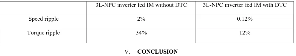
Table 3: Comparison
3L-NPC inverter fed IM without DTC 3L-NPC inverter fed IM with DTC
Speed ripple 2% 0.12%
Torque ripple 34% 12%
V. CONCLUSION
The torque and speed ripple comparison of IM fed by 3 level neutral point clamped inverter with and without DTC have been implemented and analysed in MATLAB simulink. From this, it is obtained that he torque and speed ripple of IM is reduced with SVM-DTC.
REFERENCES
[1] Shrikant Misal,Sweta T, Mamta Wandalkar, Chang Yan Tai, “Comparative Analysis of 2-Level And Multilevel Inverter Fed Coupled IM Drive Based On V/F And DTC Techniques”, Conference, vol. 24, pp. 11-26, feb 2016.
[2] Hemant Joshi, P.N. Tekkwani,Amar HIndhuja, ”Multi-level inverter for IM drives: Implementation Using Reverse Voltage Topology”, 2nd International conference on power and energy (PECon 08),pp 604-608, December 2008
[3] Hanumanji Kantari, “ Direct Torque Control of IM”, International journal of Modern Engineering research, vol 2,issue 5, sep-oct 2012, pp-3747
[4] Yassin M. Y. Hasan and Lina J. Karam, “Morphological Text Extraction from Images”,IEEE Transactions On Image Processing, vol. 9, No. 11, 2000
[5] H. J. Kim, H. D. Lee, S. K. Sul, "A New PWM Strategy For Common-Mode Voltage Reduction In Neutral-Point-Clamped Inverter-Fed AC Motor Drives", IEEE Trans. Ind. Appl., vol. 37, no. 6, pp. 1840-1845, 2001.
[6] Aarniovuori L., Laurila L., Niemela, M., Pyrhonen, J., "Measurements and Simulation of DTC Voltage Source Converter and Induction Motor Losses", IEEE Transaction on Industrial Electronics, vo!.59, no.5, pp.2277-2287, May 2012.
[7] S Mishra R., Singh S., Singh B., Kumar D., "Investigation of Transient Performance of VSI fed Induction Motor Drives Using Volt/lHz and Vector Control Techniques", Proc. IEEE Power, Control and Embedded Systems Conference (ICPCES), pp.I-6, Dec.20 Xiaoqing Liu and Jagath Samarabandu, “Multiscale Edge-Based Text Extraction From Complex Images”, IEEE Trans., 1424403677, 2006.
[8] Joong-Ho Sng, Kyon Beum Lee, “Improvement of Low Speed Performance of Three level Inverter fed Im”, IEEE Transactions on Industrial Electronics, Vol. 48, pp. 1006-1014, 2001.
[9] Telford, Dunnign, “ A Novel torque –Ripple Reduction Strategy for DTC”, IEEE Transaction on Industrial Electronics, Vol.48, pp. 867-870, 2001.