Design of Frequency Selective Absorber Based on Parallel
LC
Resonators
Kunzhe Zhang*, Wen Jiang, Junyi Ren, and Shuxi Gong
Abstract—This paper describes a method of designing Frequency Selective Absorber (FSA) which has a transmission band between two neighboring absorption bands. The proposed FSA is composed of a lossy layer on the top and a lossless layer at the bottom. The transmission characteristic is produced by the parallelLC resonators embedded in the lossy layer while the absorption ability is realized by the lumped resistors constructed in the lossy layer. An equivalent circuit model (ECM) is developed and discussed for a better understanding of this method. An FSA prototype is fabricated and measured for demonstration. Experiments show that the proposed FSA has a transmission band at the center frequency of 8.14 GHz, which agrees well with simulation. Both transmission and refection coefficients from 4.5 GHz to 7.5 GHz and from 9.1 GHz to 11.3 GHz are under −10 dB, which indicate good absorption in these frequency bands. In addition, the performance of the proposed FSA demonstrates a low sensitivity with respect to the polarization of incident EM waves and is maintained well when the incident angles range from 0◦ to 45◦.
1. INTRODUCTION
Frequency selective surface (FSS) shows a wide range of applications in electromagnetic shielding [1], satellite communication [2], metamaterials fabrication [3] and radar cross section (RCS) reduction [4–6] according to its spatial filter characteristics such as bandpass or bandstop response to electromagnetic (EM) waves [7]. Bandpass FSS (BPFSS) is more widely used among these situations. For example, stealthy radomes based on BPFSS [8] play an extremely important role in stealth aircraft. These radomes can reflect incident EM waves outside the passband to other directions to avoid specular reflection and realize monostatic RCS reduction. However, the reflected EM waves may result in a big increase in bistatic RCS in the reflection direction. In order to reduce both monostatic and bistatic RCSs outside the passband and maintain the transmission characteristic in passband, the concept of frequency selective absorber (FSA) was introduced in [9]. FSA can be seen as a combination of BPFSS and radar absorber (RA). EM waves in the passband could pass through while that outside the passband would be absorbed. The behavior of absorbing rather than reflecting makes it possible to fulfil a low RCS. Since the unique characteristic of FSA, it can be seen as a substitute of bandpass FSS in stealthy radome manufacture. In addition, it can also play an important role in electromagnetic compatibility (EMC) among different systems.
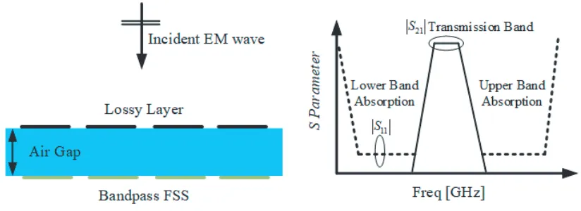
In general, FSA is composed of a lossy layer on the top and a BPFSS at the bottom, as shown in Fig. 1. BPFSS can be identified as a metal plate at the frequency outside the passband. Together with the lossy layer above, the FSA can be recognized as a circuit analog absorber (CAA) [7] and realize absorbing. However, when in the passband, BPFSS is transparent to EM waves, and the CAA model would no longer exist. As a result, EM waves can pass through. Several designs were reported about
Received 9 January 2018, Accepted 26 February 2018, Scheduled 3 March 2018 * Corresponding author: Kunzhe Zhang ([email protected]).
Figure 1. Geometry of FSA and its filter characteristic.
the FSA. However, most of them are structures with lower absorption band and upper transmission band [10–12]. The others are with lower transmission band and upper absorption band [13–15]. A few articles have reported structures whose transmission band located between two absorption bands [16– 18]. The main challenge of designing such a type of FSA is how to achieve transmission and alleviate insertion loss in the lossy layer. In past, the main method was to arrange series LC resonators in parallel with lumped resistors in the lossy layer. These seriesLC resonators resonated at the frequency of BPFSS. When in passband, the induced current would flow through resonators instead of resistors. As a result, the transmission performance could be obtained. However, this method has a disadvantage that additional bias networks are needed to place the resonators, and this would be cumbersome in designing a compact structure.
In this paper, a new method of designing FSA is proposed and investigated. It is implemented by arranging parallel LC resonators in the lossy layer. The advantage of this method is that the parallel
LC resonators can be easily integrated in the unit cell without the need for an additional bias network. In addition, the proposed FSA has a superior performance with respect to EM wave’s polarizations, stable for oblique incidence and efficient for both monostatic and bistatic RCS reduction. The paper is organized as follows. The process of designing FSA is presented and discussed in Section 2. In Section 3, the performance of the designed FSA and its advantage in bistatic RCS reduction are introduced. Fabrication details and experiment setup are described in Section 4. Conclusions are drawn in Section 5. All simulations in this paper are accomplished by using the advanced system design (ADS) and High Frequency Solution Solver (HFSS).
2. PROCESS OF DESIGNING FSA
2.1. Principle of Selecting Parallel LC Resonator
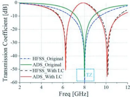
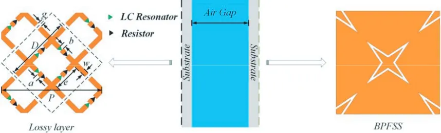
As mentioned above, the key to design the FSA is how to make the lossy layer become transparent to EM waves at the frequency of passband while maintaining low insertion loss. To achieve this purpose, tic-tac-toe grids (TTTG) are proposed and investigated, as shown in Fig. 2(a). They are printed on a thin dielectric substrate F4BM with a permittivity εr = 3.5 and thickness of 0.5 mm. The reasons for choosing TTTG are that it has a simple structure and is insensitive to the polarization of the incident EM waves as well as easy to be integrated with the lumped resonators. Fig. 3 shows the simulation results obtained from HFSS. As can be seen, the TTTG has a bandstop response around the TZ frequency at normal incidence. However, when parallel LC resonators resonating at TZ frequency are constructed in TTTG unit, as shown in Fig. 2(b), its filter characteristic would be quite different. As can be seen from the simulation results in Fig. 3, the obtained TTTG shows a bandpass response at TZ frequency. This phenomenon can be interpreted from the point view of induced current. The impedance of LC
(a) (b)
Figure 2. Top view of the TTTG unit cell and its ECM in (a) original situation and (b) with LC
resonators loaded. P = 25 mm, g = 1.2 mm, D = 16.5 mm, w = 1.2 mm, b = 0.4 mm, L = 6.61 nH, C= 0.06 pF, Le= 4.58 nH, Ce= 0.08 pF,Lr= 6.45 nH, Cr= 0.06 pF,Ls= 0.66 nH, Cs= 0.6 pF.
Figure 3. Simulated results of TTTG fromHFSS and ADS.
An equivalent circuit model (ECM) is developed to explain this electromagnetic response. According to Munk’s theory in [7], the ECM of TTTG under normal incidence is illustrated in Fig. 2(a), whereZ0 = 377 Ω is the free-space characteristic impedance,ZT =Z0/√εrthe characteristic impedance of dielectric substrate, Lthe equivalent inductance, and C the equivalent capacitance. However, when parallel LC resonators are loaded in the structure, the ECM of TTTG will change into two seriesLC
circuits arranged in parallel and then in series with the LC resonator, as shown in Fig. 2(b), where the series LrCr circuit is extracted from the structure identified in the rectangular dotted line, and the series LeCe circuit is from the structure identified by the circular dotted line. The values of equivalent inductance and capacitance in the models can be approximately calculated using formulas (1) and (2) from [19]. To make the results obtained from the circuit models agree well with that from the full-wave simulation and get more accurate values of the inductances and capacitances, these circuits are modeled and optimized in ADS. Conclusive results are plotted in Fig. 3. As can be seen, a good agreement is obtained.
L = μ0μeff D 2πln csc πw 2D (1)
C = ε0εeff 2D π ln csc πg 2D (2)
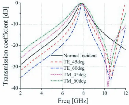
seen, it has a bandpass response at the frequency of 7.8 GHz with the insertion loss being 0.05 dB. In addition, the performance can be maintained well when the incident angles range from 0◦ to 45◦ for both TE and TM polarizations.
Figure 4. 3-D prospect view of structure and detailed unit cell of BPFSS.
Figure 5. Simulated results under different incident angles for TE and TM polarizations.
2.3. Realization of FSA
(a) (b)
Figure 6. Effect of resistances on (a) reflection coefficient and (b) transmission coefficient.
Figure 7. Structure of the designed FSA. P = 25 mm, D = 16.5 mm, e = 6.8 mm, g = 1.2 mm, w= 1.2 mm,a= 1.0 mm,b= 0.4 mm.
while the transmission characteristic should not be influenced. Fig. 6 shows the simulated results under different resistances. It can be seen that the best performance will be obtained when resistance is chosen as 240 ohm.
With determination of all parameters, the final structure of FSA is as shown in Fig. 7. There are four sets of parallel LC resonators and resistors in each TTTG unit. They are arranged in four-fold symmetry. Both TTTG and BPFSS are printed on the surface of an F4BM350 substrate with the relative permittivity of 3.5 and thickness of 0.5 mm. The air gap between these two layers is calculated about a quarter of substrate wavelength regarding to 8 GHz.
3. PERFORMANCE OF PROPOSED FSA
3.1. Absorption and Transmission Characteristic
(a) (b)
Figure 8. Simulated reflection and transmission coefficients under different incident angles for (a) TE polarization and (b) TM polarization.
(a) (b)
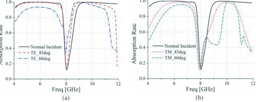
Figure 9. Calculated absorption under different incident angles for (a) TE and (b) TM polarization.
be that no miniaturization has been taken into consideration during designing process.
In order to illustrate the performance more concisely and intuitively, absorption rate is also calculated using formula (3), and the obtained results are plotted in Fig. 9.
Absorption=1−mag(S11)2−mag(S21)2 (3)
3.2. Application in Bistatic RCS Reduction
(a) (b)
Figure 10. Bistatic RCS comparison of FSA and BPFSS for (a) vertical and (b) horizontal incident plane waves at 9.5 GHz.
4. EXPERIMENT RESULTS AND DISCUSSION
An FSA prototype is also fabricated using the printed circuit board (PCB) technology to verify this method in this paper. The overall size of this prototype is 250 mm×250 mm, on which 400 sets of parallel LC resonators and resistors are soldered using surface-mount technology (SMT), as shown in Fig. 11(a). All the lumped components utilized in fabrication are with 0402 packages and produced by Murata Company. Meanwhile, plastic nuts and bolts are fixed in the four corners of prototype to maintain the necessary air gap between these two substrates.
(a) (b)
Figure 11. Pictures of fabricated FSA in (a) and measurement system in (b).
(a) (b)
Figure 12. Simulated and measured results of (a) reflection and (b) transmission coefficients.
Figure 13. Absorption rate calculated from simulated and measured results.
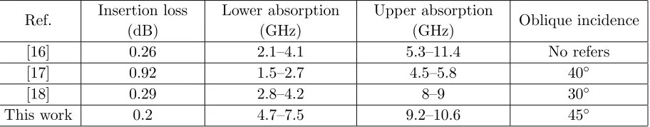
Table 1. Performance comparison of the designed FSS with the state-of-the-art.
Ref. Insertion loss (dB)
Lower absorption (GHz)
Upper absorption
(GHz) Oblique incidence
[16] 0.26 2.1–4.1 5.3–11.4 No refers
[17] 0.92 1.5–2.7 4.5–5.8 40◦
[18] 0.29 2.8–4.2 8–9 30◦
reduced. The deformation problems can be ameliorated by using foam with a permittivity close to 1 instead of plastic nuts and bolts.
The large insertion loss in turn leads to the measured absorption rate in passband bigger than that from the simulation, as shown in Fig. 13. Anyway, the method is verified well.
The performance of the proposed FSA is also compared with the state-of-the-art in Table 1, where the absorption band is defined asS11<−10 dB andS21<−10 dB. It can be seen from Table 1 that the proposed FSA has the lowest insertion loss as well as the best angular stability in all of these structures.
5. CONCLUSION
In this paper, a method of designing the FSA which has a transmission band between two neighboring absorption bands is presented and investigated. It is implemented by constructing parallelLC resonators in the unit cell. The advantage of this method over previous approaches is that no additional bias network is required to mount the lumped components. An equivalent circuit model is developed for a better understanding of this method. Meanwhile, a prototype was fabricated and measured. The measured and simulated results are in good agreement and verify the method well. In addition, the proposed FSA demonstrates a low sensitivity with respect to the polarization of incident EM waves and has a stable performance when the incident angles are up to 45◦, which indicates that it could be widely used in practice.
ACKNOWLEDGMENT
This work was supported by the National Basic Research Program of China-973 program 2015CB857100, National Natural Science Foundation of China (No. 61401327, 61471278, 61601350), the Foundation of Chinese Academy of Space Technology (CAST 2015-11), and Natural Science Basic Research Plan in Shaanxi Province of China (No. 2015JQ6217).
REFERENCES
1. Ghosh, S. and K. Srivastava, “Broadband polarization-insensitive tunable frequency selective surface for wideband shielding,” IEEE Trans. Electrom. Compat., Vol. 60, 166–172, 2018.
2. Orr, R., V. Fusco, et al., “Circular polarization frequency selective surface operating in Ku and Ka band,” IEEE Trans. Antennas Propag., Vol. 63, 5194–5197, 2015.
3. Vallecchi, A., R. J. Langley, and A. G. Schuchinsky, “Metasurfaces with interleaved conductors: Phenomenology and applications to frequency selective and high impedance surfaces,”IEEE Trans. Antennas Propag., Vol. 64, 599–608, 2016.
4. Baskey, H. B. and M. J. Akhtar, “Design of flexible hybrid nanocomposite structure based on frequency selective surface for wideband radar cross section reduction,” IEEE Trans. Microw. Theory Techn., Vol. 65, 2019–2029, 2017.
5. Zheng, J. and S. J. Fang, “A new method for designing low RCS patch antenna using frequency selective surface,”Progress In Electromagnetics Research Letters, Vol. 58, 125–131, 2016.
6. Joozdani, M. Z., M. K. Amirhosseini, and A. Abdolali, “Wideband radar cross-section reduction of patch array antenna with miniaturized hexagonal loop frequency selective surface,” Electronics Letters, Vol. 52, 767–768, 2016.
7. Munk, B. A., Frequency Selective Surfaces: Theory and Design, Wiley, New York, NY, USA, 2000. 8. Yi, B., L. Yang, and P. Liu, “Design of miniaturized and ultrathin absorptive/transmissive radome based on interdigital square loops,” Progress In Electromagnetics Research Letters, Vol. 62, 117– 123, 2016.
9. Munk, B. A., “Metamaterials: Critique and Alternatives, Wiley, Hoboken, NJ, USA, 2009.
10. Chen, Q. and L. Liu, “Absorptive frequency selective surface using parallel LC resonance,”
2015.
15. Yu, Y., Z. Shen, T. Deng, et al., “3-D frequency-selective rasorber with wide upper absorption band,” IEEE Trans. Antennas Propag., Vol. 65, 4363–4367, 2017.
16. Omar, A., Z. Shen, and H. Huang, “Absorptive frequency-selective reflection and transmission structures,”IEEE Trans. Antennas Propag., Vol. 65, 6173–6178, 2017.
17. Han, Y. and W. Che, “Switchable low-profile broadband frequency-selective rasorber/absorber based on slot arrays,”IEEE Trans. Antennas Propag., Vol. 65, 6998–7008, 2017.
18. Huang, H. and Z. Shen, “Absorptive frequency-selective transmission structure with square loop hybrid resonator,” IEEE Antennas Wireless. Propag. Lett., Vol. 16, 3212–3215, 2017.
19. Abadi, S. M. A. M. H., J. H. Booske, and N. Behdad, “Exploiting mechanical flexure as a means of tuning the responses of large-scale periodic structures,”IEEE Trans. Antennas Propag., Vol. 64, 933–943, 2016.