Available online: https://edupediapublications.org/journals/index.php/IJR/ P a g e | 2913
Grid-Connected Single-Phase Inverter for Wind/Solar
Power System
Yerrabelli Prathap Kumar
Assistant Professor Department Of Eee Khammam Institute Of Technology And Sciences Khammam, Telangana 507170, India.
Abstract: This paper exhibits a multi-input single-phase grid-associated inverter for a mixture photovoltaic (PV)/wind power system, integrated with fundamental and propelled capacities created by the creators. To accomplish great current and quick dynamic reaction to inherent varieties of half breed renewable energy sources, an
enhanced space vector
pulse-width-modulation (PWM) based prescient current control algorithm is produced. Additionally, thorough system assurance capacities are actualized for pragmatic applications. Trial comes about have approved the created multi-input inverter execution Currently, the multi-input inverters are operating in various business installations in North America.
Keywords: Grid-Connected Inverter,
Multiple-Input, Advanced Control,
Distributed Generation, Renewable Energy Systems
1. INTRODUCTION
Applications with photovoltaic (PV) energy and wind energy have quickly increased in
light of worries about worldwide
environmental change and energy sources. In any case, both solar PV and wind experience the ill effects of the intermittent idea of their assets. More PV systems are combined with wind turbines forming mixture PV/wind systems as these two sources supplement each other reducing stockpiling necessities [1]. Likewise, a crossover PV/wind system can give higher unwavering quality and convey more
general energy than either source
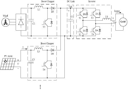
individually [2, 3]. Regularly, a half and half PV/wind power system requires isolate inverters for the PV cluster and the wind turbine separately [4]. As an elective approach, the multi-input inverter combines these renewable energy sources on the dc transport, while the air conditioner side offers a typical grid-side inverter injecting the power of all sources into the grid, in this manner simplifying the mixture PV/wind power system and reducing costs. While there were distributions on multi-input inverters and their control strategies, not very many have been providing far reaching depictions of basic and propelled control and insurance elements of these converters, alongside total testing comes about. The motivation behind this paper is to introduce a multi-input single-phase grid-associated inverter for a half breed PV/wind power system, with an emphasis on the exceptionally created current control algorithm. The proposed multi-input inverter has the following focal points: 1) transmit power from the PV cluster and the wind turbine to the grid individually or at the same time, 2) execute the maximum power point tracking (MPPT) highlight in both solar and wind energy, and 3) permit renewable power supply systems to work with a substantial scope of input voltage varieties.
2. MULTI-INPUT SYSTEM TOPOLOGY
Available online: https://edupediapublications.org/journals/index.php/IJR/ P a g e | 2914 converter modules, dc link transport
capacitors, a full-connect dc/air conditioning converter, and a grid [5]. In this multi-input system, by applying the pulse-width-modulation (PWM) control plot with proper MPPT algorithms to the lift choppers, the multi-input dc/dc converters (i.e. choppers)
can separate maximum power from both the PV exhibit and wind turbine individually and at the same time. In the interim, the dc link voltage will be managed by the dc/air conditioning inverter with space vector PWM (SVPWM) based prescient current control to
Fig-1. Multi-input system topology
2.1. Multi-Input DC/DC Converters
The various input dc/dc converters are utilized to combine a few input power
sources whose voltage levels and
additionally power limit are unique and to get directed output voltage [6, 7]. To boost the power output of the multi-input system, a maximum power extraction technique is a fundamental capacity of dc/dc converter, especially when the multi-input system has more than two separate input sources. Outline of fitting MPPT algorithms is basic for various input sources so they don't interfere with each other. As appeared in
Figure 1, every dc/dc converter has an independent MPPT controller and is controlled individually, whereby all input dc/dc converters can be totally decoupled in the control system. This multi-input system has high extend ability and adaptability, making it appropriate for half and half renewable energy applications.
2.2. DC Link Module
Available online: https://edupediapublications.org/journals/index.php/IJR/ P a g e | 2915 course through the whole system ought to
remain adjusted. The dc link module assumes an essential part in maintaining the power stream adjust in this multi-input system. As showed in Figure 1, the lift choppers are associated with a typical inverter by means of the dc link capacitors (indicated by 1 C ), which give a support between the instantaneous output power of the lift choppers and the input power of the inverter. It can be discovered that by applying a consistent dc link voltage control procedure, the power injecting into the grid can track quickly the input power of the multi-input sources through this basic control system.
2.3. DC/AC Converter
The dc/air conditioning converter changes over the dc power into air conditioning power and should encourage amazing sinusoidal air conditioning current into the grid so as to meet interconnection models [8]. In Figure 1, the dc/air conditioning converter embraces a full-connect voltage source inverter (VSI) topology, where
insulated entryway bipolar transistors (IGBTs) are utilized as power switching gadgets because of their ease and simple control. Base on the conduction conditions
of power switches T1 ∼ T4 , the dc/air
conditioning converter has four operational modes: two modes in positive grid current period and two modes in negative grid current period (see Table 1) [9]. It can be seen that the output voltage of the inverter V operation can have three esteems:
V op (1 0) =Vdc , Vop (01)=-Vdc and
Vop(11)=Vop(00)=0
Keeping in mind the end goal to accomplish astounding output current feeding into the grid, the dc/air conditioning converter requires a propelled current control algorithm so it can offer a quick dynamic reaction to the varieties of renewable energy sources and a low aggregate consonant bending (THD). This paper proposes an algorithm particularly for this multi-input
single-phase enhanced SVPWM-based
prescient current control algorithm
particularly for this multi-input single-phasegrid-associated inverter.
Table 1. Single-phase grid-connected inverter’s operational modes
3. IMPROVED SVPWM-BASED PREDICTIVE
Current Control Algorithm Most inverters for distributed generation systems are voltage-source current-controlled inverters, where the current feeding into the grid is straightforwardly controlled by a PWM methodology [10, 11]. Three noteworthy methodologies utilized for regulating the
Available online: https://edupediapublications.org/journals/index.php/IJR/ P a g e | 2916 determine the coveted normal output voltage
of the inverter Vop _av , which is then used to produce the inverter PWM gating signals. The control principle of the enhanced prescient control procedure is represented in Figure 2 [15]. The sampling point is set in front of the controlling point (i.e. at the
point when the control pulses to the inverter power changes are conveyed) by a time of the control delay. Therefore, the prescient current controller output can be quickly sent to the PWM module for updates and control delay is subsequently minimized.
Figure 2. Timing schematic of sampling point and controlling point (TD is a control delay period).
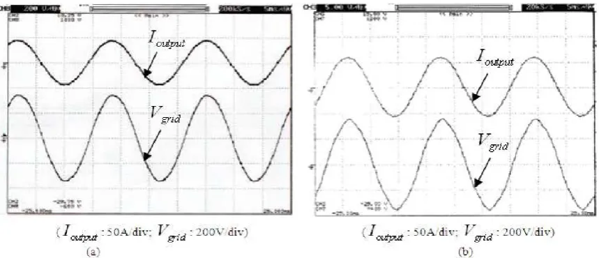
Figure 3. Inverter output current & grid voltage waveforms under the SVPWM-based predictive current control. (a) Output power of 7kW (b) Output power of 10kW
Once the requested normal inverter output voltage Vop _ av is figured, a single-phase focused SVPWM is utilized to understand the current modulation of the inverter. This plan depends on the principle of uniformly splitting the switching of IGBTs in each switching cycle among all IGBTs of a full scaffold, and along these lines utilizing a non-concurrent mode of PWM which pairs the output current swell recurrence [16]. It
Available online: https://edupediapublications.org/journals/index.php/IJR/ P a g e | 2917 consonant bending. Trial comes about have
checked the advantages of the proposed enhanced PWM system. As appeared in Figure 3 [5, 15], at an output power of 7kW, the deliberate inverter output current THD is
1.4%; while at an output power of 10kW, the deliberate inverter output current THD is 0.9% even through the grid voltage has a detectable aggregate symphonious bending of 2.3%.
Fig-4: Control block diagram of the developed multi-input inverter.
4. CONTROL SYSTEM IMPLEMENTATION
The control piece graph of the created multi-input inverter is appeared in Figure 4. The equipment usage of the control circuit is acknowledged by using an advanced flag processor (DSP) TMS320LF2407A. The detected voltage and current esteems for the PV cluster and the wind turbine are sent o
Available online: https://edupediapublications.org/journals/index.php/IJR/ P a g e | 2918 T5 and T6 according to the mistake signals
e1and e2 , separately. The power from all the lift choppers are summed in the dc link module, which cause the varieties in the dc link voltage Vdc. The blunder flag e3resulting from the examination between the deliberate dc link voltage Vdc and the
reference Vdc-ref sustains to a
corresponding integral-subsidiary (PID) controller, issuing the inverter output current reference esteem I ref . The I ref esteem and the deliberate inverter output current Ioutput and grid voltage V grid are accessible for the prescient current controller to figure the coveted normal inverter output volta Vop _ av , which is then used to create PWM entryway signals with SVPWM technique to four IGBTs of the dc/air conditioning converter for producing sinusoidal air conditioning current. Note that the dc/air conditioning converter does not require any information from the input modules to control the dc link voltage, which is managed by controlling the inverter output current. On the off chance that the deliberate dc link voltage is not as much as the reference esteem, the inverter output current will be diminished to increase the dc link voltage, and the other way around. It can be seen that the dc link voltage is managed by the dc/air conditioning converter and the
input-output power adjust can be
accomplished in such a way. Note likewise that the input dc/dc converters are secluded and individually controlled so all input converters and the dc/air conditioning converter can be totally decoupled and isolated in the control system. For handy operational contemplations, the created multi-input inverter is outfitted with programming and equipment security including the over-current of dc link and inverter output, the over-temperature of IGBTs, the over-voltage of grid, dc link and generator, the under-voltage of grid and generator, the over-recurrence and under-recurrence of the grid [9]. Figure 5 demonstrates a marketed result of double
input half breed PV/wind inverter. The power rating of this cross breed system is 12kW in absolute with 10kW for wind energy and 2kW for PV energy.
Figure 5. Dual-input hybrid PV/wind inverter.
5. Experimental Results
Available online: https://edupediapublications.org/journals/index.php/IJR/ P a g e | 2919 the two energy sources to the dc transport all
the while.
Figure 6. Measured waveforms of gate driving signals and inductor current.
Figure 7. Measured waveforms of voltage and current for the PV array and the wind turbine during their startup.
Figure 7 outlines the waveforms of voltage and current for the PV exhibit and the wind turbine when they are first associated with the multi-input inverter. In Figure 7, the output current of the PV exhibit is increased continuously as determined by the MPPT algorithm with GSS technique. In the long
run, the output power of the PV exhibit will achieve its maximum power point. The output voltage and current waveforms of the wind turbine are fundamentally the same as those of PV exhibit. It can be seen that the MPPT highlights for the PV cluster and the wind turbine are accomplished, separately. The transient reaction of the dc link voltage control is appeared in Figure 8. Figure 8(a) represents the transient reaction of the multi-input system when the multi-input power abruptly ventures up and Figure 8(b) the situation when power ventures down. At the point when the system is aggravated by a variety in input power, stable enduring state is immediately regained by adjusting the inverter output current. It can be seen that the input-output power adjust of the
proposed multi-input inverter is
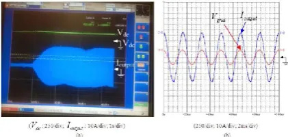
accomplished by keeping the dc link voltage steady. Figure 9(a) demonstrates the waveforms of the dc link voltage and the inverter output current when just the wind turbine is associated with the multi-input inverter. Initially, the DSP controller conveys the PWM entryway motion with MPPT highlight to switch 5 T . Once the dc link voltage achieves its pre-set esteem, the inverter begins to inject inverter output current into the grid. The extended grid voltage and inverter output current waveforms are appeared in Figure 9(b). The deliberate power factor is 1.0 and the current THD is 1.3%.
Available online: https://edupediapublications.org/journals/index.php/IJR/ P a g e | 2920 waveforms (b) The expanded grid voltage
and inverter output current waveforms
Figure 10. Waveforms of the developed multi-input inverter when only the PV array is supplying power. (a) The dc link voltage and the inverter output current waveforms (b) The expanded grid voltage and inverter output current waveforms
Figure 11. Waveforms of the developed multi-input inverter when the PV array and the wind turbine are supplying power. (a) The dc link voltage and the inverter output current aveforms (b) The expanded grid voltage and inverter output current waveforms
Figure 12. Some testing waveforms for circuit protection functions. (a) The under-voltage protection (b) The over-under-voltage protection Figure 10 demonstrates the comparative outcomes when just the PV exhibit is associated with the multi-input
inverter. The deliberate power factor is 0.99 and the current THD is 2.3%. It is noticed that the PV cluster has moderately bigger inverter output current swell. This is because of the way that the power of the PV exhibit is essentially lower than appraised power of the inverter. Figure 11(a) demonstrates the waveforms of the dc link voltage and the inverter output current when both the PV cluster and the wind turbine are associated with the proposed multi-input inverter. It can be seen that the output power of the inverter as indicated by the inverter output current changes corresponding to the power alteration of the MPPT while the dc link voltage remains steady, enabling the inverter to work with SVPWM-based prescient current control. The extended grid voltage and inverter output current waveforms are appeared in Figure 11(b), where the power factor is 0.99 and the current THD is 1.6%. Plainly the proposed cross breed PV/wind power system can draw power from the PV cluster and the wind turbine individually or at the same time. For commonsense
applications, many circuit insurance
capacities are acknowledged in the created multi-input inverter. Figure 12 demonstrates the testing waveforms for under-voltage and over-voltage insurance. The multi-input inverter works when the estimation of the grid voltage is within the pre-set range. Outside the assurance esteems, output current is interrupted by the inverter insurance system.
6. CONCLUSIONS
Available online: https://edupediapublications.org/journals/index.php/IJR/ P a g e | 2921 aggregate symphonious contortion, but then
outcomes moderately low switching
recurrence of power gadgets and sensibly low switching misfortunes yet in addition. The control circuit is executed by using a DSP to fulfill the coveted control and insurance capacities. Exploratory outcomes under various operating conditions are appeared to confirm the execution of the created multi-input inverter with the coveted highlights: 1) exchange power from the PV exhibit and the wind turbine to the grid individually or at the same time, 2)implement the MPPT in both solar and wind energy, and 3) permit the power supply system to work in an extensive variety of input voltage variety. The multi-input inverter is being utilized as a part of business items operating in various installations in North America.
REFERENCES
[1] Solero L, Caricchi F, Crescimbini F,
Honorati O, Mezzetti F. Performance
of a 10kW power electronic interface for combined wind/PV isolated generating
systems. Proceedings of IEEE
Power Electronics Specialists Conference,
PESC '96, June 23−27, 1996, Baveno,
Italy: 1027−1032.
[2] Chen Y, Liu Y, Hung S, Cheng C.
Multi-input inverter for grid-connected hybrid PV/Wind power system. IEEE Transactions on Power Electronics 2007; 22(3): 1070−1077.
[3] Wakao S, Ando R, Minami H, et al.
Performance analysis of the PV/wind/wave hybrid power generation system. Proceedings of the 3rd World Conference on Photovoltaic Energy Conversion,
May 18−18, 2003, Osaka, Japan:
2337−2340.
[4] Kjaer SB, Pedersen JK, Blaabjerg F.
A review of single-phase grid-connected inverters for photovoltaic modules. IEEE Transactions on Industry Applications
2005; 41(5): 1292−1306.
[5] Shao R, Kaye M, Chang L.
Advanced building blocks of power
converters for renewable energy based
distributed generators. Proceedings of the
8th International Conference on Power
Electronics and ECCE Asia (ICPE & ECCE), May
30−June 3, 2011, Jeju, Korea: 2168−2174.
[6] Matsuo H, Lin W, Kurokawa F,
Shigemizu T, Watanabe M. Characteristics of the multiple-input DC-DC converter. IEEE Transactions on Industrial Electronics 2004; 51 (3): 625−631.
[7] Khaligh A, Cao J, Lee YJ. A
multi-input DC-DC converter topology. IEEE Transactions on Power Electronics 2009;24(3): 862−868.
[8] Brod DM, Novotny DW. Current
control of VSI-PWM inverters. IEEE Transactions on Industry Applications 1985;IA-2(4): 562−570.
[9] Kojabadi HM, Yu B, Gadoura I,
Chang L, Ghribi M. A novel DSP-based
current controlled PWM strategy for
single phase grid connected inverters. IEEE Transactions on Power Electronics 2006; 21(4): 985−993.
[10] Kukrer O. Discrete-time current control of voltage-fed three-phase PWM
inverters. I EEE Transactions on Power
Electronics 1996; 11(2): 260−269.
[11] Abdel-Rady Y, Mohamed I, EI-Saadany EF. An improved deadbeat current
control scheme with a novel adaptive
self-tuning load model for a three-phase
PWM voltage-source inverter. IEEE
Transactions on Industrial Electronics 2007; 54(2): 747−759.
[12] Kazmierkowski MP. Current control techniques for three-phase voltage-source PWM converters: A survey. IEEE Trans Industrial Electronics 1998; 45(5): 691−703.
[13] Holmes DG, Martin DA.
Implementation of a direct digital predictive
current controller for single and three
phase voltage source inverter. Proceedings
Available online: https://edupediapublications.org/journals/index.php/IJR/ P a g e | 2922 Meeting, October 6−10, 1996, San Diego,
CA: 906−913.
[14] Marwali MN, Keyhani A. Control of distributed generation systems-part 1:
Voltages and currents control. IEEE
Transactions on Power Electronics 2004; 19(6): 1541−1550.
[15] Yu B, Chang L. Improved predictive current controlled PWM for single-phase grid- connected voltage source inverters. Proceedings of IEEE Power Electronics Specialists Conference, PESC '05, June 16−16, 2005, Recife, Brazil:231−236. [16] Shao R, Guo Z, Chang L. A PWM strategy for acoustic noise reduction for
grid- connected single-phase
inverters.Proceedings of the 22nd Annual IEEE APEC, February 25−March 1, 2007, Anaheim, CA, USA: 301−305.
Author’s profile
YERRABELLIPRATHAPKUMAR, he
obtained his M.Tech in the stream of Power Electronics from JNT University Hyderabad in 2013.He obtained his B.Tech in the stream of Electrical and Electronics
Engineering from JNT University
Hyderabad in2010.He has the teaching experience of over 4 Years. He has also guided more than 4 M.Tech and 10 B.Tech Projects.His areas of interest are power
systems and Analysis, HighVoltage