Flexible and Conformal Printed Monopoles Antennas
Asmae Hachi1, *, Hassan Lebbar1, and Mohamed Himdi2
Abstract—This paper presents the development and design of flexible and conformal printed monopoles antennas. The main objective is to control the level of radiation in broadside antenna from zero to a maximum by changing the curvature of printed board. Two printed antennas types are considered: thin wire and disk monopole. Furthermore, with the curving radius R increasing, the classical null on the broadside radiation pattern disappears gradually for both wire and disk. Increasing the curvature radius of conformal flexible antenna while keeping all other parameters same, wire monopole antenna becomes mismatched while the disk monopole antenna which remains matched for all radius of curvatures. The simulated results of various monopoles are compared successfully with measurements.
1. INTRODUCTION
The demand for wireless communication systems is rapidly growing especially flexible and conformal antennas that have become widely researched for different fields of applications. Future wireless systems will provide various services such as broadband multimedia and high speed access. The related literatures to the conformal flexible antenna have been reported by several authors. Reference [1] presents a curved strip dipole antenna combined to EBG reflector; References [2–7] present a curved micro strip antenna with the goal to miniaturize the structure. Furthermore, flexible wireless technologies requires the integration of flexible, light weight, compact, and low profile antennas, Authors in [9–14] developed antennas for various technologies with all this characteristics. In [15–17], authors present flexible antennas that are particularly suitable for use in wearable applications. It is noted that in all the cases authors report the mismatch effect due to the curvature.
In this paper, conformal flexible monopoles antennas are presented and expected to work around
f = 2 GHz using different radii of curvature and its ability to remain matched for many curvature radius. All structures use flexible, low dielectric permittivity substrate with εr = 2.2, Ts = 0.254 mm as thickness, with Tm = 18µm as copper metal thickness mounted over a metallic ground plane and excited by a 50 Ω coaxial line.
2. CONFORMAL WIRE MONOPOLE ANTENNA
2.1. Description and Design Geometry
Figure 1(a) shows a wire monopole antenna, it is a quarter wavelength line at 2.2 GHz (Lm = 34 mm) printed on a substrate with dielectric constant εr = 2.2 and thickness Ts = 0.254 mm. The antenna can be bent on a cylindrical surface withR as a curvature radius (Figure 1(b)). The width (Wm) of the line is chosen such that it avoids the effect of coupling from the reflector plane.
Received 16 December 2016, Accepted 24 February 2017, Scheduled 26 April 2017
* Corresponding author: Asmae Hachi (asmae.ma@yahoo.fr).
1 Laboratoire d’Electronique, Energie, Automatique et Traitement de l’Information, Facult´e des sciences et techniques Mohammedia,
(a) (b)
Figure 1. Structure of wire monopole antennaWm = 0.4 mm,Lm= 34 mm,Ws= 11 mm,Ls= 35 mm,
Ts= 0.254 mm. (a) Flat antenna. (b) Curved antenna on cylindrical Rohacell foam.
2.2. Wire Monopole Antenna Results
The antennas were curved on cylindrical Rohacell foam with dielectric permittivity εr = 1 and radius equal to: 12.5 mm, 17.5 mm, 45 mm and 60 mm. Antennas were simulated by CST [18], and the simulated results were compared to measurements.
Figure 2 shows the simulated (Figure 2(a)) and measured (Figure 2(b)) return losses of curved wire monopole antennas in the frequency range 1 to 3 GHz. A good agreement is obtained.
(a) (b)
Figure 2. Return loss of wire monopole antenna versusR. (a) Simulated results. (b) Measured results.
2.3. Radiation Pattern of Wire Monopole Antenna
Figure 3 shows the effect of the curvature on the radiation pattern and especially in the broadside direction. It is noted that for small radius of curvature, the null disappears when curving radius R decreases from ∞ (flat) to 12.5 mm, and the broadside level varies from −40 dB to −2.64 dB. These results are confirmed by measurements given in Figure 3(b). The measured cross polarization is lower than−25 dB compared to the simulation value −50 dB.
Figure 4 shows the H plane in the flat case and curved cases. For the flat case, the E plane has a null in the broadside, which is why we consider the Eθ as the co-polarization component at θ= 90◦, and it is plotted versusϕ (around the monopole). The level is very stable as expected (Figure 4).
(a) (b)
Figure 3. E-plane radiation pattern at 2 GHz for wire monopole antenna versus radius of curvature: Co-polarization Eθ and cross polarization Eϕ forϕ= 90◦ versus θ. (a) Simulation. (b) Measurement.
(a) (b)
Figure 4. H-plane radiation pattern at 2 GHz for wire monopole antenna versus radius of curvature. (a) Simulation. (b) Measurement. For flat wire monopole (R =∞) and curved wire with R = 60 mm & R = 45 mm, Co-polarization Eθ and cross polarization Eϕ for θ = 90◦ versus ϕ. For curved wire monopole withR = 12.5 mm &R = 17.5 mm, Co-polarization Eϕ and cross polarizationEθ forϕ= 0◦ versusθ.
2.4. Gain of Curved Wire Antennas
Table 1 shows that with increasing radius of the curvature, the gain decreases from 4.42 dB of flat wire antenna to−0.88 dB of curved wire antennaR= 12.5 mm.
Table 1. Comparison of simulated and measured gain of curved wires monopoles antennas.
R (mm) ∞ (Flat) 60 45 17.5 12.5
Simulated Gain (dBi) 4.42 3.32 2.68 2.7 −0.88
Measured Gain (dBi) 3.94 3.1 2.6 1.6 −0.1
The lower value of −0.88 dB explains that the antenna approaches the reflector plane due to the short circuit.
The gain was measured in IETR SATIMO multi-probe near-field measurement system and also by classical calibration and comparison with a known horn antenna.
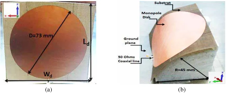
Ts= 254µm, Wd= 75 mm and Ld= 75 mm has been used.
(a) (b)
Figure 5. Photograph of the fabricated disk monopole antenna. (a) Flat disk. (b) Curved disk on cylindrical Rohacell foam.
3.2. Monopole Disk Antenna Results
Figure 6 shows the simulated and measured return losses of curved disk monopole antennas.
(a) (b)
Figure 6. Return loss of monopole disk for various curvatures. (a) Simulation. (b) Measurement.
One advantage of the disk antenna is its capability to remain matching even if it is curved. The measured results are in good agreement with simulated ones for low frequencies till up to 1.4 GHz, and for high frequencies, a shift between simulations and measurement can be observed, due to the realized prototype.
3.3. E-Plane and H-Plane Radiation Patterns
Figure 7 shows the effect of the curvature on the radiation pattern.
(a) (b)
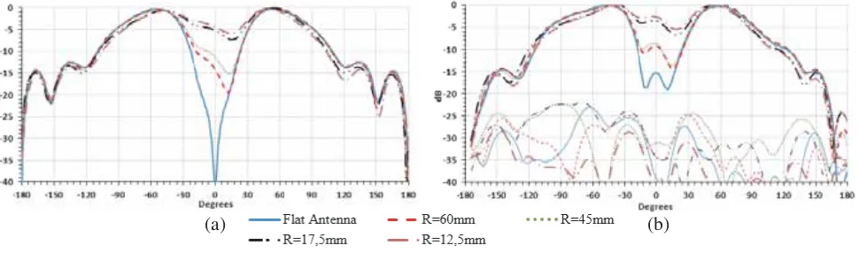
Figure 7. E-plane radiation pattern at 2 GHz for monopole disk antenna versus radius of curvature. (a) Simulation. (b) Measurement. Co-polarization Eθ and cross polarization Eϕ or ϕ= 90◦ versusθ.
It has the same remarks as those concerning the wire monopole antenna. The null disappears in the broadside direction when the disk monopole antenna is curved. The difference is that this effect appears for big radiuses of curvature (R = 45 mm and R = 60 mm). The simulated cross polarization is lower than −50 dB, but the measured one is about −25 dB. The simulated (Figure 7(a)) results are in good agreement with the measurements (Figure 7(b)).
Figure 8 shows theH plane in the flat case and curved cases. For the flat case, theE plane has a null in the broadside as the wire case, that is why we consider theEθ as the co-polarization component at θ = 90◦, and it is plotted versus ϕ(around the monopole). The level presents some small ripple as expected (Figure 8).
(a) (b)
Figure 8. H-plane radiation patterns at 2 GHz of disk monopoles antennas. (a) Simulation. (b) Measurement. For flat disk monopole (R = ∞), Co-polarization Eθ and cross polarization Eϕ or
θ= 90◦ versusϕ. For curved disk monopole (R= 60 mm & R= 45 mm) Co-polarizationEϕ and cross polarization Eθ or ϕ= 0◦ versus θ.
For the curved case, theE plane has no null in the broadside direction, and the radiation pattern is like a patch antenna case, which is why we consider the Eϕ as the co-polarization component at
ϕ= 0◦, and it is plotted versus θ. The radiation pattern in this case is much directive (like a patch) (Figure 8). It is noted that the cross polarization is quite high especially beyond±30◦. Measured results in (Figure 8(b)) show a good agreement with the simulated ones (Figure 8(a)).
3.4. Realized Gain of Disk Antennas
be reconfigured.
4. CONCLUSIONS
This paper proposes the effects of the curvature on the return loss and radiation pattern for both flexible printed wire and disk monopole antennas. The choice of Ts= 0.254 mm is good and gives the antennas more flexibility. Curvature affects the radiation in the beam axis and is more beneficial for the disk monopole antenna than a wire monopole antenna. The simulated result shows a good agreement with experimental measurements for the various conformal curved monopole antennas.
REFERENCES
1. Fhafhiem, N. and P. Krachodnok, “The study of a curved strip dipole antenna parameters on EBG reflector plane for RFID applications,” Journal WSEAS Trans. on Communications, Vol. 9, No. 6, 374–383, June 2010.
2. Geng, J. P., J. J. Li, R. H. Jin, S. Ye, X. L. Liang, and M. Z. Li, “The development of curved microstrip antenna with defected ground structure,”Progress In Electromagnetics Research, Vol. 98, 53–73, 2009.
3. Heinard, W. G. and W. H. Pepper, “Curved antenna with variably spaced slots,” pages 3, 172, 113, March 2, 1965.
4. Fhafhiem, N., P. Krachodnok, and R. Wongsan, “High directive gain antenna using shorted-end curved strip dipole on electromagnetic band gap,” PIERS Proceedings, 840–844, Xi’an, China, March 22–26, 2010.
5. Scarpello, M., D. Kurup, H. Rogier, D. Ginste, F. Axisa, J. Vanfleteren, W. Joseph, L. Martens, and G. Vermeeren, “Design of an implantable slot dipole conformal flexible antenna for biomedical applications,” IEEE Transactions on Antennas and Propagation, Vol. 59, 3556–3564, Oct. 2011. 6. Elrashidi, A., K. Elleithy, and H. Bajwa, “Input impedance, VSWR and return loss of a conformal
microstrip printed antenna for TM01 mode using two different substrates,”International Journal of Networks and Communications, Vol. 2, No. 2, 13–19, 2012.
7. Josefsson, L. and P. Persson, “Conformal array antenna theory and design,” Institute of Electrical and Electronics Engineers, Inc., 2006.
8. Hammoud, M. and F. Colombel, “Matching the input impedance of a broadband disc monopole,”
Electron. Lett., Vol. 29, 406–407, 1993.
9. Khaleel, H. R., H. M. Al-Rizzo, and A. I. Abbosh, “Design, fabrication, and testing of flexible antennas,”Advancement in Microstrip Antennas with Recent Applications, 365–383, March 6, 2013. 10. De Cos, M. E. and F. Las-Heras, “Novel flexible artificial magnetic conductor,” International Journal of Antennas and Propagation, Vol. 2012, 7 pages, Article ID 353821, Hindawi Publishing Corporation, 2012.
11. Radonic, V., K. Palmer, G. Stojanovic, and V. Crnojevic-Bengin, “Flexible Sierpinski carpet fractal antenna on a Hilbert slot patterned ground,”International Journal of Antennas and Propagation, Vol. 11, 7 pages, Article ID 980916, Hindawi Publishing Corporation, 2012.
antennas,” International Journal of Antennas and Propagation, Vol. 2012, 8 pages, Article ID 905409, Hindawi Publishing Corporation, 2012.
13. Turkmen, D., O. Soykasap, and S. Karakaya, “Development of full-scale ultrathin shell reflector,”
International Journal of Antennas and Propagation, Vol. 2012, 9 pages, Article ID 829780, 2012. 14. Kim, D.-O., C.-Y. Kim, and D.-G. Yang, “Flexible Hilbert-curve loop antenna having a triple-band
and omnidirectional pattern for WLAN/WiMAX applications,”International Journal of Antennas and Propagation, Vol. 2012, 9 pages, Article ID 687256, Hindawi Publishing Corporation, 2012. 15. Scarpello, M. L., L. Vallozzi, H. Rogier, and D. V. Ginste, “High-gain textile antenna array system
for off-body communication,” International Journal of Antennas and Propagation, Vol. 2012, 12 pages, Article ID 573438, Hindawi Publishing Corporation, 2012.
16. Osman, M. A. R., M. K. A. Rahim, N. A. Samsuri, M. K. Elbasheer, and M. E. Ali, “Textile UWB antenna bending and wet performances,”International Journal of Antennas and Propagation, Vol. 2012, 12 pages, Article ID 251682, Hindawi Publishing Corporation, 2012.
17. Boeykens, F., L. Vallozzi, and H. Rogier, “Cylindrical bending of deformable textile rectangular patch antennas,”International Journal of Antennas and Propagation, Vol. 2012, 11 pages, Article ID 170420, Hindawi Publishing Corporation, 2012.