Design and Analysis of a Bearingless Permanent-Magnet Machine
with Improved Torque Density for Stirred Tank Bioreactor
Ying Zhang, Yonghong Huang*, Ye Yuan, Jianhua Luo, and Xiaodong Chen
Abstract—A novel bearingless stirring permanent-magnet (PM) (BSPM) machine is proposed in this paper, which can offer high torque density, high efficiency, simple structure, and low cost. The novelty of the proposed machine is to provide a clean environment and no pinch-off areas in a stirred tank bioreactor and integrate appropriate magnetization directions of the PMs in the rotor. Firstly, the topology and operational principle of the proposed machine are described in detail. Then, the machine is designed for a given set of specifications, and its electromagnetic performances are analyzed by time-stepped transient finite-element method (FEM). Next, after the analysis of loss, a thermal simulation is established, complying with the design requirements. Finally, the efficiency and power factor map of the proposed BSPM machine are simulated for validation.
1. INTRODUCTION
Nowadays, with the development of the economy, it is difficult to support the requirements of mankind merely based on the supply of petrochemical resources [1]. Therefore, the utilization of biological resources has been focused and investigated by many scholars [2]. Furthermore, it should be noted that animal cell suspension culture, which has become an important part of industrial production, is the major source of biological resources. Bioreactor acting as the key equipment of cell suspension culture is an important part of maintaining cell growth [3]. Because animal cells are easily damaged in the process of cell suspension culture, bioreactor applications need high sealing and gnotobasis [4]. However, until now, a bearing machine is still commonly used in conventional bioreactors which has a lot of problems [5, 6]. First, it needs repair and maintenance from time to time, which will bring about liquid pollution in the bioreactor. Then, pinch-off areas will also be generated by using bearing topology, which will increase the possibility of cell destruction. However, by adopting a bearingless machine as a bioreactor stirrer, the aforesaid shortcomings are able to be conquered [7]. The bearingless machine is advantageous over a mechanical bearing machine in high requirements of clean environment and no pinch-off areas [8–11]. Since bearingless machines can magnetically levitate rotor, shaft and additional mechanical bearings are not required in their topologies. Hence, this machine is completely free of lubrication and does not suffer from abrasion, which guarantees long life time and low maintenance costs of the machine in bioreactor. The purpose of this paper is to apply a bearingless machine into the field of bioreactor stirrer and improve its torque density further. Therefore, a new PM array is proposed in this paper as shown in Fig. 1 together with that of an existing design.
In this paper, a novel 6-slot/16-pole exterior bearingless stirring permanent-magnet (PM) (BSPM) machine with Halbach PM array will be designed for a bioreactor with volume equaling to 400 L approximately. The topology and operational principle of the proposed BSPM machine will be described in Section 2. Then, in Section 3, by using Maxwell software, the dependable design and performance
Received 19 March 2017, Accepted 26 May 2017, Scheduled 13 June 2017 * Corresponding author: Yonghong Huang (601700690@qq.com).
optimization of a BSPM machine will be shown in detail. After that, the magnetic performance of the proposed BSPM machine will be illustrated in Section 4. Next, the simulated results will be given to verify the design requirements. Finally, the conclusions will be drawn based on the preamble analysis in Section 5.
2. MACHINE SPECIFICATION AND OPERATIONAL PRINCIPLE 2.1. Machine Specification
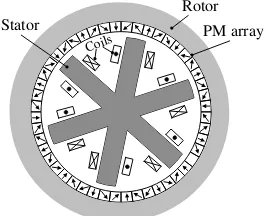
The cross section of a stirred tank bioreactor is shown in Fig. 2, in which a BSPM machine adopting an exterior rotor topology is installed. As shown in Fig. 3, the proposed BSPM machine is composed of 6 stator slots and 16 PMs. Furthermore, it is worth noting that the BSPM machine is installed at the bottom of a tank, which is beneficial to creating no unexpected flow-low regions. Besides, high torque density can be obtained by adopting exterior rotor construction and halbach magnetizing. It should be noted that the Halbach PM array adopted in the proposed machine is able to increase the torque density and reduce the harmonics of back-EMF. Concentrated-winding structure is also adopted in the proposed BSPM machine to increase torque density. In addition, this proposed machine offers a three-phase bearing force levitating the rotor. And a three-phase drive control also makes sure that the proposed BSPM machine rotates smoothly without large torque ripple.
Back iron
PM
Teeth Coils
Existing
Back iron
PM array
Teeth Coils
Proposed
(a) (b)
Figure 1. Schematics of existing and proposed PM arrays for high torque density BSPM machines. (a) Existing. (b) Proposed.
Stator
Rotor
Impeller blade
Shell
Figure 2. Cross section of a stirred tank bioreactor with a BSPM machine.
2.2. Bearing Forces and Torque
Coils
Rotor
Stator PM array
Figure 3. Proposed bearingless machine for a stirred tank bioreactor.
The passive control having 1-axis degrees of freedom and 2-rotated degrees of freedom can be obtained by adopting this winding topology. Moreover, the radial control which has 2 degrees of freedom can also be obtained. In the axial and rotated directions, the principle of passive suspension control can be illustrated in Fig. 4. Besides, it should be noted that the proposed topology has sufficient reluctance forces to stabilize the axial position and tilting. When the axial displacement occurs, the magnetic force will pull the rotor back to the equilibrium position. In the radial direction, the active suspension can stabilize the 2 degrees of freedom. It is worth noting that the model of levitation force has close relationship with the winding number and current. Each coil creates the radial and tangential forces, and their superposition leads to the total composite bearing force. The mathematical model of each coil ncan be obtained as follows:
Fn,x(θr) =kx·[cos(n−1)·60◦+ sin(n−1)·120◦]·cos [(n−1)·120◦+θr]·N ·Ini
Fn,y(θr) =ky·[sin(n−1)·60◦+ cos(n−1)·120◦]·sin [(n−1)·120◦+θr]·N·Ini (1) wherekx and ky represent the force factor in thex-direction andy-direction, respectively, and N is the number of windings,Ini the current suspension component and θr the electrical rotor angle.
Coils Stator Coils
PM PM
Coils Stator Coils
PM
PM
Figure 4. The control of the passive suspension.
As a result, the total composite bearing force in x-direction and y-direction can be derived as
follows: ⎧
⎪ ⎪ ⎪ ⎪ ⎨ ⎪ ⎪ ⎪ ⎪ ⎩
Fx = 6
n=1
Fn,xcos [θr+ 60◦(n−1)]
Fy = 6
n=1
Fn,ysin [θr+ 60◦(n−1)]
(2)
by each coiln in the proposed BSPM machine can be given by
Tn(α) =nT ·sin2(p·α+ (n−1)·120◦)·N·Imi (3) where α is the mechanical angle, p the magnet pole-pair number, nT the factor of drive current, and Imi the current torque component. As a result, the total torque of BSPM machines can be derived as follows:
T = 6
n=1
Tn= 3·n·T ·N·Imi (4)
3. MACHINE DESIGN
The relationship between maximum electromagnetic torque and electromagnetic load can be obtained as follows:
Temmax= √
2π
4 Bδ1LefD 2
i1A×10−4 (5)
where Bδ1 is the amplitude of air-gap flux density, Lef the axial length of BSPM machine, Di1 the diameter of stator, and A the effective value of electrical load. When the electromagnetic load is selected, the main dimensions of BSPM machines can be derived as:
D2i1Lef =
4Tem√max×10−4 2πBδ1A
(6)
The leading design parameters of the basic module of the proposed machine are defined in Fig. 5. The choice of these parameters can be guided by the sizing equation and should follow a number of design criterions [13, 14]. The ratio between axial length and diameter in BSPM machine can be expressed as:
λ= Lef
Di ,
(7)
it is within the range from 0.6 to 0.7 in BSPM machines. Considering the rated torque, rated speed and restrictions of the container size, the stator outside diameter and axial length are about 116 mm and 74 mm, respectively.
For the proposed machine, these parameters in Fig. 5 play a key role in its electromagnetic performance. So, it is very important to optimize these parameters, determined by considering their effect on back-EMF and other performance indicators, such as torque and inductances. The air-gap length in BSPM machines is defined as δg. The thickness of the rotor encapsulation δ1 is 1 mm, the thickness of the stator encapsulationδ2 1 mm, and the thickness of tank wallδ3 1 mm. To keep the fluid
0 20 40 60 80
2 3 4 5 6 7 8 9 10
Peak back-EMF (V)
Hpm (mm)
Figure 6. Variation of peak back-EMF with Hpm.
8.6 9 9.4 9.8 10.2
9 11 13 15 17 19 21
T
orque (Nm
)
Stator tooth width (mm)
Figure 7. Variation of torque with stator tooth width.
sheer forces low, a fluid gapδ4 equal to 2 mm should also be required. Therefore, the air-gap of BSPM machine can be obtained as follows:
δg=δ1+δ2+δ3+δ4 = 5 mm (8)
In addition, the effect of the thickness of PMHpmon the back-EMF is illustrated in Fig. 6. It should be noted that the peak back-EMF is increased by raisingHpm. However, ifHpmis too large, the remaining back iron gets saturated. Therefore, the stronger PMs do not result in higher magnetic flux density. And the maximum back-EMF can be obtained whenHpmequals 8 mm. The last main design parameter is the stator tooth widthWt. As shown in Fig. 7, the coherence betweenWs and torque is depicted. It should be noted that the general trend of torque is increasing-deceasing. And the maximum torque is able to be obtained whenWs is equal to 15 mm. Based on Maxwell software, the optimal parameters is listed in Table 1.
4. PERFORMANCE EVALUATION
4.1. Winding Topology and Field Distributions
The slot electrical potential star vectogram is shown in Fig. 8(a). It is seen that Phases A, B, and C mutually differ 120 degrees. Based on Fig. 8(a), stator winding connection in BSPM machines can be obtained (see Fig. 8(b)). As shown in Fig. 9, the air-gap flux density of proposed machine is analyzed by FEM and compared with that of the existing one. It can be seen from Fig. 9 that the proposed machine has higher magnetic flux density than the existing one. Furthermore, as shown in Fig. 9(b), the 8th harmonic is the working harmonic generating torque, and 4th, 14th, 16th, 20th, and 26th are tooth harmonics, which are the main source of generating magnet eddy current (EC) loss.
A B
C
1,4 2,5
3,6
120 °
A B C X Y Z
Coil 1 Coil 2 Coil 3 Coil 4 Coil 5 Coil 6
(a) (b)
Table 1. Design parameters of existing machines.
Parameter Symbol Value
Rated power P 500 W
Slot number q 6
Pole-pair number p 8
Outer rotor radius Ro 76 mm
Inner rotor diameter Ri 63 mm
Axial length L 74 mm
Magnet thickness HP M 5 mm
Stator tooth width Wt 15 mm
Air-gap thickness δg 5 mm
Rotor thickness Hr 13 mm
Rated speed n 500 r/min
Rated torque T 10 Nm
-1.2 -0.8 -0.4 0 0.4 0.8 1.2
0 60 120 180 240 300 360
Air
-g
ap flux
density
(T)
Rotor position (elec. deg.)
Exsiting Proposed
0.0 0.2 0.4 0.6 0.8
1 3 5 7 9 11 13 15 17 19 21 23 25
Air
-g
ap flux
density
(T)
Harmonic order
(a) (b)
Existing Proposed
Figure 9. Comparison of air-gap flux density and harmonic spectra. (a) Air-gap flux density. (b) Harmonic spectra.
-0.2 -0.1 0 0.1 0.2
0 60 120 180 240 300 360
F
lux
(W
b)
Rotor position (elec.deg.)
Proposed phase A
Existing phase A
Figure 10. Comparison of PM flux linkages.
-80 -40 0 40 80
0 60 120 180 240 300 360
Back-EMF (V)
Rotor position (elec. deg.)
Existing phase A Proposed phase A
Figure 11. Comparison of phase back-EMF.
4.2. Flux Linkage, Back-EMF and Inductance
The phase back-EMFE can be expressed as
E = dψ
dt = dψ
dxv (9)
Therefore, it can be obtained from Eq. (9) that the back-EMF is only connected with the rate of change in the flux linkage. Since the amplitude of flux linkage in the proposed machine is greater than that in existing machine, the back-EMF of the proposed machine is also greater than that of existing machine as shown in Fig. 11.
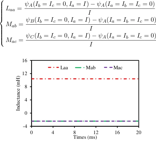
The self- and mutual-inductances of each phase can be predicted by FEM as well, as shown in Fig. 12. For example, the self- and mutual-inductances of phase-A are calculated as
⎧ ⎪ ⎪ ⎪ ⎪ ⎪ ⎪ ⎨ ⎪ ⎪ ⎪ ⎪ ⎪ ⎪ ⎩
Laa = ψA
(Ib =Ic= 0, Ia=I)−ψA(Ia=Ib =Ic= 0) I
Mab= ψ
B(Ib =Ic= 0, Ia=I)−ψA(Ia=Ib =Ic= 0) I
Mac= ψC
(Ib =Ic = 0, Ia=I)−ψA(Ia=Ib =Ic = 0) I
(10)
-4 0 4 8 12 16
0 4 8 12 16 20
Inductance (m
H)
Times (ms)
Laa Mab Mac
Figure 12. Comparison of self- and mutual-inductances.
4.3. Torque, Loss and Thermal Analysis
Because Halbach structure is beneficial to improving the ability of magnetic congregate effect, the torque of the proposed machine is obviously greater than that of the existing machine, as shown in Fig. 13. Furthermore, it can also be seen from Fig. 13 that the torque has linear growth when the range of Q-axis current is from 0 to 36 A, which indicates that the proposed BSPM machine has overload ability.
0 20 40 60 80
0 6 12 18 24 30 36
T
o
rque (Nm)
Q-axis current (A) 2D Existing 2D Proposed 3D Existing 3D Proposed
Finally, it should be noted that the results calculated by 2D FEM are in a good agreement with 3D FEM.
High temperature of the machine not only damages the lifetime of the machine, but also affects the environment of a stirred tank bioreactor. Hence, in order to analyze the thermal properties of the proposed BSPM machine, the occurring loss needs to be determined. Iron losses including hysteresis loss, EC loss and excess loss are generated in the stator and rotor owing to the change of magnetic fields [15]. In addition, due to cogging effect and ample magnetomotive force (MMF) harmonics in BSPM machines, magnet EC loss does exist in BSPM machines [16–18]. Besides, copper loss will also be generated in the stator windings [19]. Taking the circumferential and radial components of magnetic flux density variation into consideration, the iron loss in watts per kilogram can also be derived as in Fig. 4.
PF e= n
i=1
Kc·(i2·f2)·(Br, i2 +Bt, i2 ) +Kh·f· ⎡ ⎢ ⎢ ⎣
Bt, m2 ·
1 + c·Bt, m1 N
i=1 ΔBt,i
+Br, m2 ·
1 + c·Br, m1 N i=1
ΔBr,i
⎤ ⎥ ⎥ ⎦
+Ke·(i1.5·f1.5)·(Br, i1.5 +Bt, i1.5)
(11)
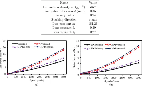
whereKh,Kc, and Ke are the coefficients of hysteresis loss, EC loss, and excess loss, respectively; f is the fundamental frequency;Bt,i andBr,i are amplitude of the ith harmonic of the tangential and radial magnetic flux density, respectively; Bt,m and Br,m are the maximum value of the ith harmonic of the tangential and radial magnetic flux density, respectively. Finally, the total iron loss can be given by the sum of every part of BSPM machines. Fig. 14 compares the variations of stator and rotor iron loss with respect to rotor speed for which the same method and lamination steel characteristic as given in Table 2
Table 2. Material characteristics (M19-29G).
Name Value
Lamination density δ (kg/m3) 7872 Lamination thickness d(mm) 0.35
Stacking factor 0.94
Stacking direction z-axis
Loss constant kh 184.23
Loss constant kc 0.39
Loss constant ke 0.27
0 5 10 15 20 25
0 500 1000 1500 2000 2500 3000 3500
Stator iron loss (W
)
Speed (r/min) Existing Proposed 3D Existing 3D Proposed
0 2 4 6 8 10 12
0 500 1000 1500 2000 2500 3000 3500
Rotor iron
loss
(W)
Speed (r/min) 2D Existing 2D Proposed 3D Existing 3D Proposed
(a) (b)
0 1 2 3 4 5 6
0 2 4 6 8 10 12 14 16
Eddy
current
loss
(W
)
Times (ms)
2D Existing 2D Propsoed 3D Existing 3D Proposed
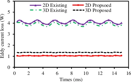
Figure 15. Comparison of eddy current loss at rated speed 500 r/min.
are employed. It is seen that the general trend of stator and rotor iron loss with respect to speed is in parabolic growth. Since the air-gap flux density generated by the proposed machine is greater than that of the existing machine, the iron loss of the proposed machine both in stator and rotor is slightly greater than that of the existing machine. Furthermore, the magnet EC loss caused by asynchronous harmonics can also be calculated as follows:
PP M =
∞
h=1
P M
|Jh|2 2σ dv
(12)
where Jh and σ are the EC density of hth harmonics and conductivity, respectively. Fig. 15 makes a comparison of magnet EC loss between the proposed machine and existing machine at rated speed 500 r/min. It is worth noting that the magnet EC loss of existing machine is lower than that of the proposed machine, which is due to the segmentation of PMs. Magnet segmentation is conducive to cutting the EC path, thus decreasing magnet EC density. In addition, it is well known that copper loss is the main source for machine loss. Based on Joule’s law, it depends on the resistance and the current flowing through it [20]. The copper loss can be calculated as follows:
PCu= 6·R·(2n2−2n+ 1)·(Id,rms+Ib,rms)2 (13) where R is the coil resistance; Id,rms and Ib,rms are the rms value of the drive current and bearing current, respectively; nrepresents the ratio between the drive and bearing currents.
Ultimately, the efficiencyη of the proposed machine is given by
η =
1−
p p2+
p
×100% (14)
p = pF e+pCu+pP m+pΩ+pad (15) whereP2 is the output power, ΣP the total loss, PF e the total iron loss, PCu the copper loss, PP m the magnet EC loss, PΩ the mechanical loss, and Pad the stray loss. The efficiency map and power factor map of the proposed BSPM machine are shown in Fig. 16. When the speed is from 0 to 500 r/min, the machine operates at constant torque. When the speed is from 500 to 2000 r/min, the machine operates at constant power. Finally, at rated condition, it can be seen from Fig. 16(a) and Fig. 16(c) that the efficiency and power factor of the proposed BSPM machines are 0.97 and 0.77, respectively. In this paper, efficiency map is calculated by Ansoft script. In fact, it is calculated by many points, and these points also paint a cloud picture after processing. Actually, there are no data on both sides of the small area. Therefore, there does exist some problems at almost zero speed and low torque region. However, it has little effect on our calculation, because the machine cannot operate at this region for a long time. Furthermore, Fig. 16(b) illustrates the total loss in contour plot over torque-speed range. It can be obviously seen that the total loss is increased with the increase of rotor speed.
(c)
(a) (b)
Figure 16. Efficiency, total loss map and power factor map. (a) Efficiency. (b) Total loss. (c) Power factor.
Figure 17. Thermal analysis of the proposed machine.
default Motor-CAD values. Next, it can be seen from Fig. 17 that the rotor temperature of the proposed machine operating at rated condition is 106.9◦C, which indicates that it complies with the environment of bioreactor tank. Also, the average temperature of stator and windings are approximately equal to 155◦C and 158◦C. Finally, it can be seen that the maximum temperature of PMs is 108◦C, which cannot increase the risk of PMs irreversible demagnetization. Compared with practical temperature, the indoor temperature and wind is the source to affect the accuracy of simulated results. However, it is able to be neglected within error. In general, according to thermal analysis, it can be concluded that the proposed BFPM machine can operate well without overlarge heat.
5. CONCLUSIONS
In this paper, a novel BSPM machine that employs a clean environment, no pinchoff areas in a stirred tank bioreactor and appropriate magnetization directions of the PMs in the rotor has been described. Based on simulated results, it is shown that the proposed machine exhibits high torque density with relatively large air-gap necessary for the targeted application in a stirred tank bioreactor. A thermal analysis reveals that the loss is in an acceptable range for rated operation condition so that there is no negative effect on the bioreactor application. Hence, the proposed BSPM machine is especially competent for bioreactor stirring applications.
ACKNOWLEDGMENT
This work was supported by the Natural Science Foundation of Jiangsu Province of China (Grants NO BK20151345), and by the Priority Academic Program Development of Jiangsu Higher Education Institutions (PAPD.).
REFERENCES
1. Montiel-Moreno G., J. Zechinelli-Martini, and G. Vargas-Solar, “SLSELS: Semantic integration system for exploitation of biological resources,” 2009 Mexican International Conference on Computer Science, 197–202, 2010.
2. Artis, F., D. Dubuc, J. Fournie, M. Poupot, and K. Grenier, “Microwave dielectric spectroscopy for biological cells suspensions analysis and proliferation evaluation,” 2014 44th European Microwave Conference, 275–278, 2014.
3. Daniele, M., F. Vozzi, A. Cisternino, G. Vozzi, and A. Ahluwalia, “A high-throughput bioreactor system simulating physiological environments,” IEEE Transactions on Industrial Electronics, Vol. 55, No. 10, 3273–3280, 2008.
4. Maki, A., T. Ryynanen, J. Verho, J. Kreytzer, J. Lekkala, and P. J. Kallio, “Indirect temperature measurement and control method for cell culture devices,” IEEE Transaction on Automation Science and Engineering, Vol. 1, No. 99, 1–10, 2016.
5. Henson, M. A., “Biochemical reactor modeling and control,” IEEE Control Systems Magazine, Vol. 26, No. 4, 54–62, 2006.
6. Ye, S., and K. T. Chau, “Chaoization of DC motors for industrial mixing,” IEEE Transactions on Industrial Electronics, Vol. 54, No. 4, 2024–2032, 2007.
7. Bartholet, M. T., T. Nussbaumer, S. Silber, and J. W. Kolar, “Comparative evaluation of polyphase bearingless slice motors for fluid-handling applications,”IEEE Transactions on Industry Applications, Vol. 45, No. 5, 1821–1830, 2009.
8. Park, S. and C. Lee, “Decoupled control of a disk-type rotor equipped with a three-pole hybrid magnetic bearing,”IEEE/ASME Transactions on Mechatronics, Vol. 15, No. 5, 793–804, 2010. 9. Ooshima, M., A. Chiba, T. Fukao, and M. A. Rahman, “Design and analysis of permanent
10. Yang, S. and M. Huang, “Design and implementation of a magnetically levitated single-axis controlled blood pump,” IEEE Transactions on Industrial Electronics, Vol. 56, No. 6, 2213–2219, 2009.
11. Reichert, T., T. Nussbaumer, W. Gruber, and J. W. Kolar, “Bearingless Permanent-Magnet motor with 4/12 slot-pole ratio for bioreactor stirring applications,” IEEE/ASME Transactions on Mechatronics, Vol. 16, No. 3, 431–439, 2011.
12. Dajaku, G., W. Xie, and D. Gerling, “Reduction of low space harmonics for the fractional slot concentrated windings using a novel stator design,” IEEE Transaction on Magnetics, Vol. 50, No. 5, 1–12, 2014.
13. Jian, L. and K. T. Chau, “Design and analysis of a magnetic geared electronic-continuously variable transmission system using finite element method,”Progress In Electromagnetics Research, Vol. 107, 47–61, 2010.
14. Jian, L., G. Xu, Y. Gong, J. Song, J. Liang, and M. Chang, “Electromagnetic design and analysis of a novel magnetic-gear-integrated wind power generator using time-stepping finite element method,” Progress In Electromagnetics Research, Vol. 113, 351–367, 2011.
15. Bramerdorfer, G. and D. Andessner, “Accurate and easy-to-obtain iron loss model for electric machine design,” IEEE Transactions on Industrial Electronics, Vol. 64, No. 3, 2530–2537, 2017. 16. Bianchi, N. and E. Fornasiero, “Impact of MMF space harmonic on rotor loss in fractional-slot
permanent-magnet machines,” IEEE Transaction on Energy Conversion, Vol. 24, No. 2, 323–328, 2009.
17. Chai, F., P. Liang, Y. Pei, and S. Cheng, “Magnet shape optimization of surface-mounted permanent-magnet motors to reduce harmonic iron losses,” IEEE Transaction on Magnetics, Vol. 52, No. 7, Article ID: 7300504, 2015.
18. Choi, G. and T. M. Jahns, “Reduction of eddy-current losses in fractional-slot concentrated-windings synchronous PM machines,” IEEE Transaction on Magnetics, Vol. 52, No. 7, Article ID: 8105904, 2016.
19. Gonzalez, D. A. and D. M. Saban, “Study of the copper losses in a high-speed permanent-magnet machine with form-wound windings,”IEEE Transactions on Industrial Electronics, Vol. 61, No. 6, 3038–3045, 2014.