Surface Wave-Based Radio Communication through Conductive
Enclosures
Igor I. Smolyaninov1, *, Quirino Balzano2, and Dendy Young3
Abstract—A surface wave antenna operating in the 2.4 GHz band and efficient for launching surface electromagnetic waves at metal/dielectric interfaces is presented. The antenna operation is based on the strong field enhancement at the antenna tip, which results in efficient excitation of surface waves propagating along nearby metal surfaces. Since surface electromagnetic waves may efficiently tunnel through deep subwavelength channels from inner to outer metal/dielectric interface of a metal enclosure, this antenna is useful for broadband radio communication through various conductive enclosures, such as typical commercial Faraday cages.
1. INTRODUCTION
It is very difficult to employ broadband radio signals for communication through conductive enclosures, such as underground tunnels, metal or partially metallic shipping containers, and metallic test chambers. Performance of conventional RF communication schemes in such situations is limited by very small RF skin depthδ, which may be calculated as:
δ =
1
πμ0σν,
(1)
where σ is the medium conductivity, and ν is the communication frequency [1]. By the Bethe’s [2] expression for the transmission of a conventional TEM wave through a subwavelength aperture
T ∝aλ4, (2)
whereais the aperture size, andλis the free space wavelength. As a result, conventional techniques of RF communication are impractical in situations where the walls of an enclosure are highly conductive, and the openings in the walls (if any) have deep subwavelength dimensions.
On the other hand, it is well established in the nanophotonics literature that efficient coupling to surface electromagnetic modes [3] (such as surface plasmon-polaritons at metal/dielectric interfaces) enables efficient light transmission through deep subwavelength apertures [4–7]. Five to six orders of magnitude transmission enhancement have been observed in these experiments compared to the theoretical predictions based on Eq. (2). We have used a conceptually similar approach to demonstrate a battery-powered 2.45-GHz transmitting surface wave antenna, which is capable of sending video signals from inside a locked −90 dB isolation commercial Faraday cage. This novel capability may be used for improving Wi-Fi connectivity in buildings and underground tunnels, as well as remote examination of metal and partially metal enclosures, such as shipping containers and metallic test chambers. For
Received 18 July 2019, Accepted 26 August 2019, Scheduled 6 September 2019
* Corresponding author: Igor I. Smolyaninov (igor.smolyaninov@saltenna.com).
example, very recently, surface electromagnetic modes have been successfully used to achieve broadband RF communication in seawater over distances, which considerably exceed the skin depth in seawater [8].
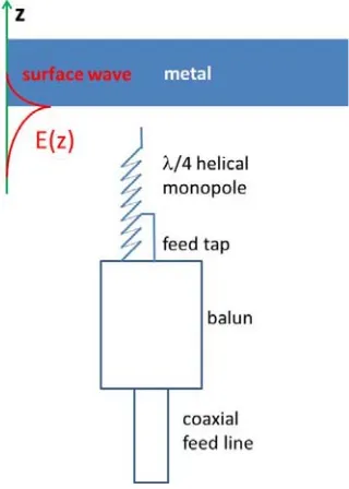
The principle of operation of the surface electromagnetic wave-based 2.4 GHz antenna is illustrated in Fig. 1. The electromagnetic field of the surface electromagnetic wave is partially longitudinal, which means that a good surface wave antenna needs to be placed in the vicinity of the metal surface, and it needs a strong field enhancement at its apex, which “pushes” charges along the metal surface. Below we will discuss the details of such a surface wave antenna design and describe the operation of a battery-powered 2.4 GHz transmitter capable of sending high quality video signals through conductive enclosures.
Figure 1. Schematic geometry of a 2.4 GHz surface wave antenna design based on helical monopole shorted to its feed line outer conductor. The tip of the antenna is shown near a flat metal surface where it excites an omnidirectional surface electromagnetic wave. The electromagnetic field of the surface electromagnetic wave is partially longitudinal, which means that an efficient surface wave antenna needs a strong field enhancement at its apex, which “pushes” charges along the metal surface. A large charge accumulation at the tip is achieved using a low driving point impedance antenna. The antenna tip is also sharpened in order to take advantage of the lightning rod effect.
2. ANTENNA DESIGN AND DISCUSSION
An extensive review of the basic electromagnetic properties of surface electromagnetic waves (SEW) may be found in [3]. In particular, a SEW solution of Maxwell equations arises when the real part of the dielectric permittivity ε changes sign across the interface. Unlike the conventional TEM waves in free space, this SEW propagating solution is partially longitudinal. It has a non-zero component ofE field along the propagation direction. A dielectric constant of a good metal is well described by the Drude model [9]:
εm(ω) = 1− ω
2
p
ω2+iωΓ, (3)
whereωp is the plasma frequency, and Γ is the damping factor. The real part of εm(ω) is
Reεm(ω) = 1− ω
2
p
At low frequencies
Reεm(ω)≈1−ω
2
p
Γ2, (5)
so the real part of εof typical metals is large and negative, while air has ε = 1. Therefore, air-metal interfaces support the SEW modes.
As illustrated in Fig. 2, the SEW momentum is larger than the momentum of conventional TEM wave at the same frequency. Therefore, a plane TEM wave incident on a flat metal-dielectric interface cannot excite SEW due to momentum conservation. This is the main reason that SEWs are rarely seen in conventional RF experiments. However, in the configuration shown in Fig. 1 the metal surface which supports SEW propagation is placed within the near-field region of the antenna. In addition, placing the antenna near the plane metal wall breaks the conservation law for the momentum component parallel to the wall. Under such conditions, various dipole sources are known to excite the SEW waves. However, compared to the conventional dipole antennas whose efficiency is compromised near metal surfaces, an additional advantage of our surface wave antenna design is that it is optimized for excitation of partially longitudinal waves. The strong field enhancement at the antenna apex “pushes” charges along the metal surface, leading to efficient excitation of SEWs.
Figure 2. Dispersion law of a surface electromagnetic wave (SEW) at a metal-dielectric interface [3].
k = 2π/λSEW is the SEW wave vector, c is the speed of light, and ε1 is the dielectric permittivity of
the dielectric medium.
SEW wavelengthλSEWmay become much smaller than the wavelength of conventional TEM waveλin
free space. As a result, application of the modified Bethe’s equation to such a situation results in much higher transmission:
T ∝
a λSEW
4
(6)
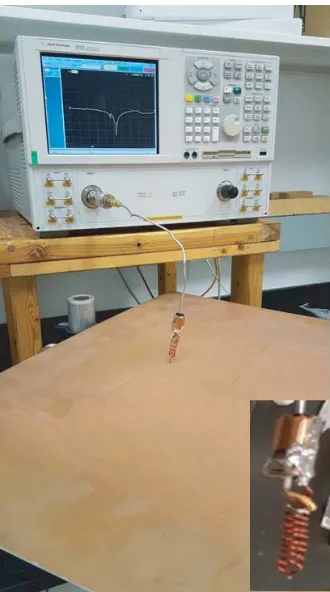
In this paper, following the analysis in [10], a λ/4 helical monopole (see Fig. 1) resonant at 2.4 GHz, which is more efficient than a linear short monopole of the same length, has been used as a structure radiating SEWs since the helical monopole design considerably enhances the electric field at its tip [11]. The charge at the tip is proportional to the divergence of the antenna current. A larger charge accumulation at the tip can be achieved using a low driving point impedance antenna, e.g., a helix. The antenna tip has also been sharpened in order to take advantage of the lightning rod effect, which increases the electric field near the tip, thus leading to enhanced SEW emission, as described in detail in [12]. This antenna requires careful tuning because the feed alters the electrical length of the antenna. A tuning procedure is illustrated in Figs. 3 and 4, which shows measurements of S11 of the fabricated helical antennas resonant at 2.45 GHz, while they were nearly touching a large
conductive copper plane. The length and diameter of the helical antenna were selected for resonance at 2.45 GHz near the conductive plane. The finalized helical monopole was 3 cm long with 0.7 cm diameter. The tapping point for a 50 Ω match to a feeding coaxial line was determined using the setup of Fig. 3. Depending on the tapping point location, the radiative behavior of the helical antenna may be optimized for either 2D surface wave radiation or 3D radiation into free space, as illustrated in Fig. 4. The final tuning of the antenna was performed by maximizing the received video signal outside a closed commercial Faraday chamber.
Figure 3. Measurements ofS11 of the fabricated helical antenna resonant at 2.45 GHz while nearly in
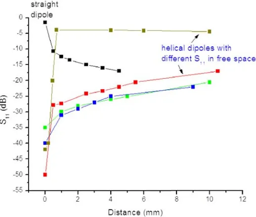
Figure 4. Tuning of the fabricated helical antennas resonant at 2.45 GHz via measurements of S11 as
a function of distance from the large copper plane. The tuning parameter is the tapping point to a feeding coaxial line. Behavior of regular (straight) dipole antenna (see Fig. 6) optimized for radiation into free space is presented for a comparison.
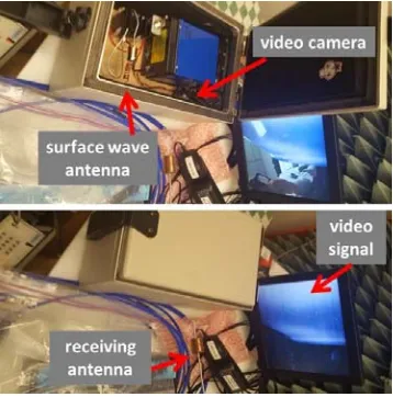
Figure 5. Transmitting (a) and receiving (b) components of the SEW-based video transmission apparatus. The electromagnetic shielding enclosure (EMI) is rated at −90 dB isolation.
3. MEASURED RESULTS
dipole antenna or a SEW antenna identical to the one of the transmitter. The received video signal was amplified, decoded, and displayed on a live video monitor. If necessary during the measurements, the real-time visual output of the receive antenna was also decomposed into signal spectral amplitudes and displayed by a spectrum analyzer. The performance comparison of a conventional dipole antenna and the SEW antenna is illustrated in Figs. 6 and 7.
As expected, the conventional dipole antenna was not able to transmit video signal from inside the locked Faraday cage. The received signal fell below the −92 dBm sensitivity limit of the video receiver circuit and was undetectable (video receiver RF Links, model VRX-24L, which uses NTSC/PAL encoding was used in this experiment). On the other hand, when the SEW transmit antenna was used inside the locked cage at the same transmit operating power, the live video connection was maintained. The typical received signals in this case (of the order of−55 dBm) are indicated in Fig. 8.
Figure 6. Conventional 2.4 GHz dipole antenna cannot transmit video signal from a locked−90 dB Faraday cage.
Figure 7. Surface wave antenna keeps transmit-ting video signal from a locked −90 dB Faraday cage when operated at the same output power as the conventional dipole antenna shown in Fig. 6.
The SEW-mediated mechanism of 2.4 GHz video signal transmission through the locked Faraday cage has been verified by the transmitted signal measurements near the Faraday cage as a function of distance from the outside wall of the cage; results are shown in Fig. 8. The exponential decay of the transmitted signal outside of the cage confirms its SEW character. We noted that the signal received farther away from the cage (in the far field zone) originates from the transmitted SEW field reaching the cage corners and scattering into the conventional propagating TEM fields. We have also verified that the transmitting SEW antenna efficiency strongly depends on the distance between the antenna tip and the inner wall of the Faraday cage, as illustrated by the red curve in Fig. 8. In both cases, the antenna was tuned for maximum signal outside the Faraday cage.
We should note that the most obvious imperfection of the Faraday cage used in our experiments is its door. It is quite visible from the top photos in Figs. 6 and 7 that the door is protected from leakage by a metallic mesh, which is positioned in between the metallic double walls of the cage. The mesh has periodic millimeter-scale openings. SEWs are known to penetrate well through these kinds of periodic sub-wavelength defects [4–7].
We should also note that grounding the Faraday cage does not eliminate the video signal transmission from the inner SEW antenna. As noted above, the SEW field is partially longitudinal. It has a nonzero electric field component parallel to the metal walls of the cage. Therefore, grounding the cage at some point(s) does not prevent SEW from propagating along the inner and outer walls of the cage, followed by scattering of the SEW propagating along the outer wall into the conventional TEM modes propagating in free space.
4. CONCLUSION
In this work, we have demonstrated a successful realization of a 2.4 GHz band surface wave antenna that is efficient for launching surface electromagnetic waves at metal/dielectric interfaces. The antenna operation is based on the strong field enhancement at the antenna tip, which results in efficient excitation of surface waves propagating along nearby metal or highly conductive surfaces. Since surface electromagnetic waves may efficiently tunnel through deep subwavelength channels from inner to outer metal/dielectric interface of a metal enclosure, this technique will be useful for broadband radio communication through various metal enclosures and Faraday cages. We anticipate that the demonstrated SEW antenna technique is scalable to other RF frequency ranges. We also believe that our work will result in considerable improvement of Wi-Fi connectivity in buildings, underground tunnels, as well as remote examination of metal and partially metal enclosures, such as shipping containers and metallic test chambers. For example, in a very recent development [8], surface electromagnetic modes were used successfully to achieve broadband RF communication in seawater over distances, which considerably exceed the skin depth in seawater. Thus, the SEW-based antenna solutions together with new capabilities enabled by novel materials [13–20] will considerably enhance the range of THz and RF applications of surface electromagnetic waves.
REFERENCES
1. Cheng, D. K.,Fundamentals of Engineering Electromagnetics, Chapter 8, London, Pearson, 1992. 2. Bethe, H. A., “Theory of diffraction by small holes,” Phys. Rev., Vol. 66, 163, 1944.
3. Zayats, A. V., I. I. Smolyaninov, and A. Maradudin, “Nano-optics of surface plasmon-polaritons,” Physics Reports, Vol. 408, 131–314, 2005.
4. Ebbesen, T. W., H. J. Lezec, H. F. Ghaemi, T. Thio and P. A. Wolff, “Extraordinary optical transmission through sub-wavelength hole arrays,” Nature, Vol. 391, 667–669, 1998.
5. Elliott, J., I. I. Smolyaninov, N. I. Zheludev, and A. V. Zayats, “Polarization control of optical transmission of a periodic array of elliptical holes in a metal film,” Optics Letters, Vol. 29, 1414– 1416, 2004.
7. Lezec1, H. J., A. Degiron, E. Devaux, R. A. Linke, L. Martin-Moreno, F. J. Garcia-Vidal, and T. W. Ebbesen, “Beaming light from a subwavelength aperture,”Science, Vol. 297, 820–822, 2002. 8. Smolyaninov, I. I., Q. Balzano, C. C. Davis, and D. Young, “Surface wave-based underwater radio
communication,” IEEE Antennas and Wireless Propagation Letters, Vol. 17, 2503–2507, 2018. 9. Drude, P., “Zur elektronentheorie der metalle,” Annalen der Physik, Vol. 306, 566–613, 1900. 10. Balzano, Q., et al., “Field and temperature gradients from short conductors in a dissipative
medium,”International Journal of Antennas and Propagation, Vol. 2007, Article ID 57670. 11. Balzano, Q., et al., “The near field of helical antennas,” IEEE Trans. on Vehicular Technology,
Vol. 31, No. 4, 173–185, 1982.
12. Smolyaninov, I. I., D. L. Mazzoni, and C. C. Davis, “Imaging of surface plasmon scattering by lithographically created individual surface defects,”Phys. Rev. Letters, Vol. 77, 3877–3880, 1996. 13. Sanne, A., R. Ghosh, A. Rai, M. N. Yogeesh, S. H. Shin, A. Sharma, K. Jarvis, L. Mathew, R. Rao,
D. Akinwande, and S. Banerjee, “Radio frequency transistors and circuits based on CVD MoS2,”
Nano Lett., Vol. 15, 5039, 2015.
14. Wang, H., X. Wang, F. Xia, L. Wang, H. Jiang, Q. Xia, M. L. Chin, M. Dubey, and S. Han, “Black phosphorus radio-frequency transistors,” Nano Lett., Vol. 14, 6424, 2014.
15. Politano, A., G. Chiarello, R. Samnakay, G. Liu, B. G¨urbulak, S. Duman, A. A. Balandin, and D. W. Boukhvalov, “The influence of chemical reactivity of surface defects on ambient-stable InSe-based nanodevices,”Nanoscale, Vol. 8, 8474, 2016.
16. Politano, A., L. Viti, and M. S.Vitiello, “Optoelectronic devices, plasmonics and photonics with topological insulators,” APL Materials, Vol. 5, 035504, 2017.
17. Politano, A., M. S. Vitiello, L. Viti, D. W. Boukhvalov, and G. Chiarello, “The role of surface chemical reactivity in the stability of electronic nanodevices based on two-dimensional materials ‘beyond graphene’ and topological insulators,”Flat Chem., Vol. 1, 60, 2017.
18. Viti, L., A. Politano, and M. S. Vitiello, “Black phosphorus nanodevices at terahertz frequencies: Photodetectors and future challenges,” APL Materials, Vol. 5, 035602, 2017.
19. Giordano, M. C., S. Mastel, C. Liewald, L. L. Columbo, M. Brambilla, L. Viti, A. Politano, K. Zhang, L. Li, A. G. Davies, E. H. Linfield, R. Hillenbrand, F. Keilmann, G. Scamarcio, and M. S. Vitiello, “Phase-resolved terahertz self-detection near-field microscopy,”Opt. Express, Vol. 26, 18423, 2018.
![Figure 2. Dispersion law of a surface electromagnetic wave (SEW) at a metal-dielectric interface [3].k = 2π/λSEW is the SEW wave vector, c is the speed of light, and ε1 is the dielectric permittivity ofthe dielectric medium.](https://thumb-us.123doks.com/thumbv2/123dok_us/1966790.1259424/3.612.199.425.301.465/figure-dispersion-electromagnetic-dielectric-interface-dielectric-permittivity-dielectric.webp)