N A N O E X P R E S S
Open Access
Peak modulation in multicavity-coupled
graphene-based waveguide system
Jicheng Wang
1,2*†, Xiaosai Wang
1†, Hongyan Shao
1, Zheng-Da Hu
1, Gaige Zheng
3and Feng Zhang
2*Abstract
Plasmonically induced transparency (PIT) in a multicavity-coupled graphene-based waveguide system is
investigated theoretically and numerically. By using the finite element method (FEM), the multiple mode effect can be achieved, and blue shift is exhibited by tunable altering the chemical potential of the monolayer graphene. We find that the increasing number of the graphene rectangle cavity (GRC) achieves the multiple PIT peaks. In addition, we find that the PIT peaks reduce to just one when the distance between the third cavity and the second one is 100 nm. Easily to be experimentally fabricated, this graphene-based waveguide system has many potential applications for the advancement of 3D ultra-compact, high-performance, and dynamical modulation plasmonic devices.
Keywords:Plasmonically induced transparency, Graphene-based waveguide, Multiple peak modulation
Background
Electromagnetically induced transparency (EIT) refers to a quantum destructive interference phenomenon be-tween two excitation pathways with a sharp transparency window [1–3]. Based on the EIT effect, many potential applications in quantum information, ultrafast optical switching, nonlinear optics, slow light effect have been proposed [4–6]. However, the practical applications of EIT effect were restricted because of the difficulty with demanding experimental conditions [7]. With theoretical analysis and experimental operation, EIT-like response occurred in the near-field coupling and the phase coup-ling, was observed to address the problem [8]. Especially, as a novel phenomenon analogous to EIT, plasmonically induced transmission (PIT) [9–15] based on surface plasmon polaritons (SPPs) has been researched in highly integrated metal-based nanoscale plasmonic devices due to its unique properties for allowing the propagation of light to overcome the diffraction limit and manipulating light at subwavelength scales [16–19]. Nevertheless,
these metallic plasmonic structures are mainly applied and achieved in the visible regions. The abilities to dy-namically control the PIT response remain the signifi-cant challenges.
Graphene, a single-layer carbon atom arranged in a honeycomb lattice, has been vigorously investigated as a promising platform for plasmonic result from its re-markable characteristics, such as strong mode confine-ment, low loss, and active tunability [20]. In particular, by applying extra gate voltage, magnetic fields, and chemical doping, the surface conductivity of graphene can be changed, which gives an increasing development on tunable plasmonic devices [21–24]. Considering the unique properties, graphene can also support propaga-tion of SPPs, which are polariton modes of photon and electron density waves along a conductor and dielectric interface. Graphene surface plasmon polaritons (GSPPs) can not only be excited for a wide range of wavelengths from near-infrared to terahertz (THz) region [25], but also display lower propagation loss due to the high car-rier mobility of graphene at room temperature [26]. Moreover, it is easier to control the propagation of GSPPs by altering the chemical potential of graphene without re-fabricating the structure. The highly tunable plasmonic graphene nanoresonators at mid-infrared have been observed by Brar et al. using infrared micros-copy [27]. A two coplanar graphene strips coupling * Correspondence:[email protected];[email protected]
†Equal contributors
1School of Science, Jiangsu Provincial Research Center of Light Industrial
Optoelectronic Engineering and Technology, Jiangnan University, Wuxi 214122, China
2Key Laboratory of Semiconductor Materials Science, Institute of
Semiconductors, Chinese Academy of Sciences, 912, Beijing 100083, China Full list of author information is available at the end of the article
system supported on substrates [28], and a graphene-based resonator-coupled waveguide system [29], the tun-able multiple layer graphene-based absorber [30, 31] have been researched. However, the modulation of PIT peaks with multi-cavity-coupled graphene sheet system has not been discussed.
In this paper, we investigate a novel 3D graphene-based plasmonic waveguide system. This system is com-posed of one guided graphene waveguide (GGW) coupled to one to three graphene rectangle cavity (GRC). The multimode PIT phenomenon has been ob-served in our proposed system. Two transmission dips exist with one GRC while two PIT peaks appear in the dip-position of the transmission spectra with two GRCs. The increasing number of the GRC placed above the GGW introduces the multi-PIT peaks. In addition, the multimode PIT effects can be dynamically controlled by varying the chemical potential and the coupling distance. Moreover, the modulation of PIT peaks with three cav-ities is investigated in detail. For the advancement in 3D ultra-compact high-performance PIT devices, our work may have potential applications in the PIT-peaks modu-lation, slow light and optical switching.
Methods
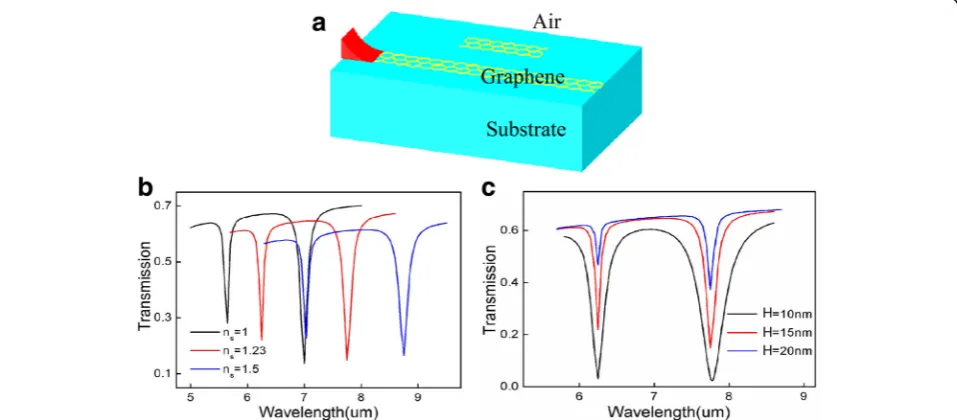
A schematic of the structure of the designed tunable peak modulation devices based on three GRCs wave-guide system is shown in Fig. 1. The incident wave prop-agates along the graphene waveguide to the right port while some parts of the GSPPs couple to the graphene cavities. The width and length of the three same cavities aredand L, respectively. The width of the waveguide is D. Here,Danddare fixed to be 10 nm,Lis 100 nm. In addition,H and h represent the waveguide-cavity coup-ling distance and the cavity-cavity coupcoup-ling distance, re-spectively. Chemical potential μc is applied to the
graphene waveguide and cavities. We carry out the three-dimensional numerical simulations by using the FEM [32]. The Kubo formula has governed the surface conductivity of graphene σgincluding the intraband and
interband transition contributions [20]:
σintra¼ ie 2μ
c
πℏ2ðωþiτ−1Þ; ð1Þ
σinter¼ ie 2
4πℏ ln
2μc−ðωþiτ−1Þℏ
2μcþðωþiτ−1Þℏ
þ ie2kBT
πℏ2ðωþiτ−1Þln exp −
μc kBT
þ1
: ð2Þ
It depends on chemical potentialμc, photon frequency
ω, momentum relaxation time τ, and temperature T. Here,erepresents the electron charge. In our numerical simulations, the incident wave is at mid-infrared where the influence of interband transition in graphene can be negligible. In this case, the optical conductivity can be simply given by:
σgð Þ ¼ω ie2μ
c=πℏ2
ωþiτ−1 : ð3Þ
The following equation shows the equivalent permit-tivity of graphene [33]:
εg¼1þ iσgη0
k0Δ ; ð
4Þ
where the wave vector in vacuum k0= 2π/λ and the
in-trinsic impedance of air η0≈377Ω. The monolayer
gra-phene support TM-polarized SPPs is only in
consideration for our analysis. The dispersion relation of this TM GSPP surface wave follows the equation:
βGSPP ¼k0
ffiffiffiffiffiffiffiffiffiffiffiffiffiffiffiffiffiffiffiffiffiffiffiffi
1− 2
η0σg
2
s
; ð5Þ
where βGSPP is the propagation constant of GSPPs.
De-fined asneff=βGSPP/k0, the effective index of GSPPs
fea-tures the capacity for confine SPPs on graphene. Obviously, from the equations above, the Re(neff)
increases for a fixed wavelength as the chemical potential μc decreases, which intends the GSPPs are
better confined at lower chemical potential. Importantly, with a slight change in chemical potential, the Re(neff)
varies greatly, which leads to the design of dynamically tunable peak modulation devices. The transmission of
[image:2.595.57.538.612.703.2]GSSPs with one graphene cavity satisfies the resonant condition:
2ReβGSPPLþ2φ1¼2mπ: ð6Þ
Here,φ1is the additional phase [34].mstanding for the
order of resonant mode (RM), is an integer.Lis length of the cavities. Moreover, it should be noted that we assume the substrate to be air in our 3D simulations for simplifi-cation. The reason is given in the following part.
Results and Discussion
As shown in Fig. 1, GSPPs can be coupled to the GRCs when the incident wave propagates along the GGW. In order to fully understand the properties of the proposed waveguide system, we investigate the transmission characteristics of the GGW with one graphene cavity as shown in Fig. 2. Figure 2a shows the schematic with the same geometrical parameters as Fig. 1a. For future experimental design purpose, we also give the transmission spectra with different substrates, in whichns= 1
andns= 1.23 represent the substrate to be air and SiO2,
re-spectively. From Fig. 2b, we can see that the different sub-strates (such as silica, silicon carbide) only lead to a read shift in the transmission spectra. The transmission with different coupling distancesHis shown in Fig. 2c. As the distance in-creases, the waveguide-cavity coupling gets weaken mean-while more energy transport to the right port and thus the value of the dips becomes larger.
The effective refractive index of the waveguide mode in relation to the incident wavelength is depicted in Fig. 3a. The insert figure gives the sectional view of the mode distribution propagating along the waveguide. It is
apparent that the value of decreases as the chemical potential increasing, which agrees well with theoretical equations mentioned above. Figure 3b indicates the propagation length increases with the chemical potential increases. In addition, as the incident wavelength increase, the propagation length has a decrease. The dependence of the transmission spectra on the chemical potential is shown in Fig. 3c. Moreover, a blue shift of the transmission dip1 (λ1= 7 μm at μc= 0.3 eV) and
dip2 (λ2= 5.65 μm at μc= 0.3 eV) is observed.
Subse-quently, Fig. 3d provides the two-dips-position as a function of chemical potential which emerge a good linear relationship.
Based on the transmission characteristics of the graphene waveguide with one cavity, we investigate the properties of the system with multi-cavities. The black line in Fig. 4a presents two obvious transmission dips at the incident wavelengthsλ1= 7μm andλ2= 5.65μm can
be generated in the transmission spectra in the condition that the one GRC is in resonance with the waveguide. There are, respectively, two obvious transmission PIT peaks at the two resonant wavelengths due to the near-field coupling between the three cavities, and the wave-guide as depicted in Fig. 4a with red line. The counter profiles of the magnetic field distributions |Hz| with one
cavity in the two resonant wavelengths are shown in Fig. 4b and c. Atλ1= 7μm, the third order RM exists in
the GRC, while λ2= 5.65 μm satisfies the fourth order
resonant condition. At the same time, most parts of the GSPPs cannot confine to the GRC and thus propagate to the right port of the GGW. The PIT effect can be shown by the transmission spectrum with multi-cavities under
[image:3.595.59.538.492.702.2]Fig. 3aThe effective refractive index andbthe propagation length of the waveguide mode as a function of the incident wavelength with different chemical potential,cthe transmission spectra of the system under different chemical potential,dthe transmission dips as a function of chemical potential
[image:4.595.59.538.88.355.2] [image:4.595.58.539.405.696.2]the chemical potential μc= 0.3 eV in Fig. 4d. The
in-creasing number of the GRCs gives rise to the PIT peaks. When only one rectangle cavity is placed above the waveguide, it behaves as a Fabry-Perot (FP) resonator due to the near-field coupling. Adding another cavity to the system, the PIT window appears which is attributed to the additional cavity-cavity coupling. The PIT peaks are located atλ1= 6.95μm andλ2= 5.6μm, respectively.
It indicates that two GRCs generate one PIT peak. Sub-sequently, we investigate the transmission properties of the waveguide system with three and even four graphene cavities. As shown in Fig. 4d, three cavities lead to two peaks and four cavities correspond to three PIT peaks. Therefore, the number of the PIT peaks is always one less than the cavity numbers as we expect. We can also see that the value of the PIT peaks is almost the same. This is because the incident wavelengths do not satisfy the resonant condition so the GSPPs propagate along the waveguide without coupling losses. What is more,
the maximum value of the transmission is less than 1 because of the scattering losses and the absorption of the materials.
As the surface conductivity of graphene depends on the chemical potential can determine the propagation of the GSPPs, we can achieve the dynamic tunability of the PIT peak by changing the chemical potential of cavities and waveguide. The transmission spectrum with different chemical potential is shown in Fig. 5a. It is obvious that with the increase of the chemical potential, the PIT peaks happen to a blue shift which can be explained by the onant condition between the graphene cavities. The res-onant wavelength satisfies λ∝(2π2ℏcD/α0μc)
1/2∝
(1/μc) 1/2
[35, 36]. As a result, a blue shift is obtained in the trans-mission peaks with chemical potential increasing. The four PIT peaks in one transmission spectrum are named as peak1 ~ 4 from right to left in turn. A good linear rela-tionship between peak wavelength and chemical potential is exhibited in Fig. 5b.
Fig. 5aThe transmission spectra with different chemical potential.bPeak wavelengths as a function of chemical potential
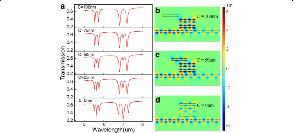
Fig. 6aThe transmission spectra with different coupling distanceC,b–dthe counter profiles of the magnetic field distributions |Hz| at peak4
[image:5.595.58.540.88.208.2] [image:5.595.57.540.484.703.2]To further explore the influence of the rectangle cav-ities to the PIT peaks, we change the position of the third cavity with other parameters remain the same. Here, C is used to describe the distance between the center of the second cavity and the center of the third one. It is apparent that the cavity coupling between the second and the third cavity is gradually weakened as C increases. Therefore, the number of PIT peaks in the two PIT windows decrease to one at C= 100 nm as depicted in Fig. 6a. In order to illuminate the resonant characteristics of the PIT effect, we give the magnetic field distributions in z direction with different coupling distances C in Fig. 6b–d at incident wavelength λ= 5.55μm. As shown in Fig. 6d, there is no cavity coupling between the second and the third cavity resulting from the distanceCis too far to confine. Thus, the peak num-ber reduces to 1 in good consistent with the transmis-sion spectrum seen in Fig. 6a.
Conclusion
In conclusion, our work particularly has focused on the peak modulation of the multicavity-coupled graphene-based waveguide system by using FEM. One graphene cavity leads to a transmission dip while two cavities gen-erate a PIT window in the transmission spectra. The number of the PIT peaks is always one less than the number of the cavities. Moreover, not only a blue shift can be achieved in transmission spectra with the in-creasing of chemical potential, but also a good linear re-lationship between peak wavelength and chemical potential is obtained. The increasing coupling distanceC can lead to the subdued cavity-cavity resonance and eventually achieve the peak modulation. We believe the proposed structures, easily to be operated, may promise the applications for tunable multiple mode filters and slow light devices.
Abbreviations
EIT:Electromagnetically induced transparency; FEM: Finite element method; GGW: Guided graphene waveguide; GRC: Graphene rectangle cavity; GSPPs: Graphene surface plasmon polaritons; PIT: Plasmonically induced transparency; THz: Terahertz; TM: Transverse magnetic
Acknowledgements
This work is supported by the National Natural Science Foundation of China (Grant Nos. 11504139, 11504140, 41675154), the Natural Science Foundation of Jiangsu Province (Grant Nos. BK20140167, BK20140128, BK20141483), the Key Laboratory Open Fund of Institute of Semiconductors of CAS (Grant No. KLSMS-1405), Jiangsu Provincial Research Center of Light Industrial Optoelectronic Engineering and Technology (Grant No. BM2014402), and the Six Major Talent Peak Expert of Jiangsu Province (Grant No. 2015-XXRJ-014).
Authors’contributions
JW and FZ conceived the idea. SW, JW and HS calculated properties of the proposed structure, analyzed the data, and wrote the manuscript. JW, GZ and FZ revised the manuscript. ZDH, FZ, GZ, and JW supervised the project. All authors read and approved the final manuscript.
Competing interests
The authors declare that they have no competing interests.
Author details
1School of Science, Jiangsu Provincial Research Center of Light Industrial
Optoelectronic Engineering and Technology, Jiangnan University, Wuxi 214122, China.2Key Laboratory of Semiconductor Materials Science, Institute of Semiconductors, Chinese Academy of Sciences, 912, Beijing 100083, China.
3School of Physics and Optoelectronic Engineering, Nanjing University of
Information Science & Technology, Nanjing 210044, China.
Received: 19 October 2016 Accepted: 14 December 2016
References
1. Harris SE (1997) Electromagnetically induced transparency. Phys Today 50: 36–42
2. Gu J, Singh R, Liu X, Zhang X, Ma Y, Zhang S, Zhang W (2012) Active control of electromagnetically induced transparency analogue in terahertz metamaterials. Nat Commun 3:1151
3. Tassin P, Zhang L, Zhao R, Jain A, Koschny T, Soukoulis CM (2012) Electromagnetically induced transparency and absorption in metamaterials: the radiating two-oscillator model and Its experimental confirmation. Phys Rev Lett 109:187401
4. Lu H, Liu X, Wang L, Gong Y, Mao D (2011) Ultrafast all-optical switching in nanoplasmonic waveguide with Kerr nonlinear resonator. Opt Express 19: 2910–2915
5. Harris SE, Hau LV (1999) Nonlinear Optics at Low Light Levels. Phys Rev Lett 82:4611–4614
6. Krauss TF (2008) Why do we need slow light? Nat Photonics 2:448–450 7. Papasimakis N, Fedotov VA, Zheludev NI, Prosvirnin SL (2008) Metamaterial
analog of electromagnetically induced transparency. Phys Rev Lett 101: 253903
8. Xu Q, Sandhu S, Povinelli ML, Shakya J, Fan S, Lipson M (2006) Experimental realization of an on-chip all-optical analogue to electromagnetically induced transparency. Phys Rev Lett 96:123901
9. Han Z, Bozhevolnyi SI (2011) Plasmon-induced transparency with detuned ultracompact Fabry-Perot resonators in integrated plasmonic devices. Opt Express 19:3251–3257
10. Zhang ZR, Zhang LH, Li HQ, Chen H (2014) Plasmon induced transparency in a surface Plasmon polariton waveguide with a comb line slot and rectangle cavity. Appl Phys Lett 104:231114
11. Guo YH, Yan LS, Pan W, Luo B, Wen KH, Guo Z, Luo XG (2012) Electromagnetically induced transparency (EIT)-like transmission in side-coupled complementary split-ring resonators. Opt Express 20:24348–24355 12. He ZH, Li HJ, Zhan SP, Cao GT, Li BX (2014) Combined theoretical
analysis for plasmon-induced transparency in waveguide systems. Opt Lett 39:5543–5546
13. Cao GT, Li HJ, Zhan SP, Xu HQ, Liu ZM, He ZH, Wang Y (2013) Formation and evolution mechanisms of plasmon-induced transparency in MDM waveguide with two stub resonators. Opt Express 21:9198–9205 14. Cao GT, Li HJ, Deng Y, Zhan SP, He ZH, Li BX (2014) Plasmon-induced
transparency in a single multimode stub resonator. Opt Express 22: 25215–25223
15. Wang GX, Zhang WF, Gong YK, Liang J (2015) Tunable slow light based on Plasmon-induced transparency in dual-stub-coupled waveguide. IEEE Photon Technol Lett 27:89–92
16. Barnes WL, Dereux A, Ebbesen TW (2003) Surface Plasmon subwavelength optics. Nature 424:824–830
17. Gramotnev D, Bozhevolnyi S (2010) Plasmonics beyond the diffraction limit. Nat Photonics 4:83–91
18. Ozbay E (2006) Plasmonics: Merging photonics and electronics at nanoscale dimensions. Science 311:189–193
19. Zand I, Abrishamian MS, Berini P (2013) Highly tunable nanoscale metal-insulator-metal split ring core ring resonators (SRCRRs). Opt Express 21:79–86
20. Novoselov KS, Geim AK, Morozov SV, Jiang D, Zhang Y, Dubonos SV, Grigorieva IV, Firsov AA (2004) Electric field effect in atomically thin carbon films. Science 306:666–669
21. Bao QL, Loh KP (2012) Graphene photonics, plasmonics, and broadband optoelectronic devices. ACS Nano 6:3677–3694
23. Wang X, Chen C, Pan L, Wang J (2016) A graphene-based Fabry-Pérot spectrometer in mid-infrared region. Sci Rep 6:32616
24. Song C, Xia X, Hu ZD, Liang Y, Wang J (2016) Characteristics of plasmonic Bragg reflectors with graphene-based silicon grating. Nanoscale Res Lett 63:419
25. Li ZB, Yao K, Xia FN, Shen S, Tian JG, Liu YM (2015) Graphene plasmonic metasurfaces to steer infrared light. Sci Rep 5:12423
26. Gao W, Shu J, Qiu C, Xu Q (2012) Excitation of plasmonic waves in graphene by guided-mode resonances. ACS Nano 6:7806–7813 27. Brar VW, Jang MS, Sherrott M, Lopez JJ, Atwater HA (2013) Highly confined
tunable mid-infrared plasmonics in graphene nanoresonators. Nano Lett 13(6):2541–2547
28. Li HJ, Wang LL, Liu JQ, Huang ZR, Sun B, Zhai X (2014) Tunable, mid-Infrared ultra-narrowband filtering effect induced by two coplanar graphene strips. Plasmonics 9:1239–1243
29. Lu H (2014) Plasmonic characteristics in nanoscale graphene resonator-coupled waveguides. Appl Phys B 118:61–67
30. Yuan H, Yang H, Liu P, Jiang X, Sun X (2014) Mode manipulation and near-THz absorptions in binary grating-graphene layer structures. Nanoscale Res Lett 9:90
31. Lobet M, Majerus B, Henrard L, Lambin P (2016) Perfect electromagnetic absorption using graphene and epsilon-near-zero metamaterials. Phys Rev B 93:235424
32. Jin JM (2002) The finite element method in electromagnetics. Wiley-IEEE Press, New York
33. Vakil A, Engheta N (2011) Transformation optics using graphene. Science 332:1291–1294
34. Nikitin AY, Low T, Moreno LM (2014) Anomalous reflection phase of graphene plasmons and its influence on resonators. Phys Rev B 90:041407 35. Cheng H, Chen SQ, Yu P, Duan XY, Xie BY, Tian JG (2013) Dynamically
tunable plasmonically induced transparency in periodically patterned graphene nanostrips. Appl Phys Lett 103:203112
36. Koppens FH, Chang DE, de Abajo FJG (2011) Graphene plasmonics: a platform for strong light-matter interactions. Nano Lett 11:3370–3377
Submit your manuscript to a
journal and benefi t from:
7Convenient online submission
7Rigorous peer review
7Immediate publication on acceptance
7Open access: articles freely available online
7High visibility within the fi eld
7Retaining the copyright to your article