International Journal of Emerging Technology and Advanced Engineering
Website: www.ijetae.com (ISSN 2250-2459,ISO 9001:2008 Certified Journal, Volume 5, Issue 4, April 2015)
404
Solar Street Light Control with Single Axis Auto-Tracker and
Self-Timed Power Saver
Manisha Joshi
1, Sushil Salins
2, Parag Wadhwa
3, Ronit Hasija
4, Dhiraj Singh
5Vivekanand Education Society Institute of Technology, Collector’s colony, Chembur, Mumbai-74, India
Abstract— The proposed paper presents a system where the street lights are powered by the energy harnessed by the single axis solar tracker. This system is also equipped with a Street Light Energy Saver which is designed to save energy by turning off selected streetlights late at night when traffic volume is low and manual work of switching it on and off is eliminated. It is as simple to program as an alarm clock and it also conserves more energy than a PIR sensor. Thus by using this system, solar energy is efficiently utilized thereby minimizing energy consumption and eliminating manual work.
Keywords— Single axis solar tracker, light dependent resistors(LDRs), LED street lights, solar panel, solar cells.
I. INTRODUCTION
Natural resources such as coal, petroleum and natural gas take millions of years to form naturally and cannot be replaced as fast as they are being used. Eventually it is considered that fossil fuels will become too costly to harvest and we will need to shift its reliance to other sources of energy preferably renewable resources. SOLAR STREET LIGHT CONTROL WITH SINGLE AXIS SUN TRACKER could bring a revolution in the fields concerning street-light usage.
A solar tracker is a device for orienting a solar photovoltaic panel or concentrating solar reflector or lens toward the sun. The sun's position in the sky varies both with the seasons (elevation) and/or time of day as the sun moves across the sky.
Solar powered equipment works best when pointed at or near the sun, so a solar tracker can increase the effectiveness of such equipment over any fixed position, at the cost of additional system complexity. Solar trackers may be active or passive and may be single axis or dual axis. Single axis trackers usually use a polar mount for maximum solar efficiency.
Fig1. Single axis Tracker
International Journal of Emerging Technology and Advanced Engineering
Website: www.ijetae.com (ISSN 2250-2459,ISO 9001:2008 Certified Journal, Volume 5, Issue 4, April 2015)
405
II. BLOCK DIAGRAM
III. DESCRIPTION OF BLOCK DIAGRAM
A. LDRs
The Light is incident on the solar panel and due to ‗ Photovoltaic effect‘ the solar panels absorb the energy from the sun. There are two LDRs on the solar panel which are used for the tracking mechanism. The digital value of these LDRs are displayed on the LCD display. IC 0808 ADC is used for the analog to digital conversion, The tracker will move in such a manner that same amount of energy level is sensed by both the LDRs which indicates that maximum amount of energy is harnessed by the solar cells.
B. AT89s51
The whole system is microcontroller-based and we have used microcontroller AT89s51. The AT89S51 is a low-power, high-performance CMOS 8-bit microcontroller with 4K bytes of In System Programmable Flash memory. The device is manufactured using Atmel‘s high-density nonvolatile memory technology and is compatible with the industry- standard 80C51 instruction set and pin out.
The on-chip Flash allows the program memory to be reprogrammed in-system or by a conventional nonvolatile memory programmer.
PIN Diagram
C. POWER SUPPLY
AT89s51 has an operating voltage of 4- 5.5 V. LED street lights exceed mercury vapor's 31 lm/W. You can find higher efficacy measurement from for high pressure sodium lamps. It is just misleading because It includes wasted light that in turn wastes energy. In the market, many power efficiency of LED street lights can reach up to 80lm/w.
D. ADC 0808
International Journal of Emerging Technology and Advanced Engineering
Website: www.ijetae.com (ISSN 2250-2459,ISO 9001:2008 Certified Journal, Volume 5, Issue 4, April 2015)
406 The converter features a high impedance chopper stabilized comparator, a 256R voltage divider with analog switch tree and a successive approximation register.
The channel multiplexer can directly access any of 8-single-ended analog signals.
E.RECHARGEABLE BATTERY
Battery will store the electricity from solar panel during the day and provide energy to the fixture during night. The life cycle of the battery is very important to the lifetime of the light and the capacity of the battery will affect the backup days of the lights.
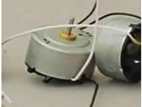
F. DCMOTORS
[image:3.612.46.294.343.530.2]The system proposed uses a solar panel dc motor. The Solar panels convert light energy into electrical energy and this energy is Direct Current (DC) so it can be used by motors that run on dc electrical power.
Fig 2: DC motors
IV. DEVELOPMENT STAGES AND PROCESS
A. PROBLEM DEFINITION STAGE
This is the very first stage to develop any project. It actually defines the aim and the concept of the project. The main aim is to design a system which can be practically implemented in our day to day life.
B. DESIGNING BLOCK DIAGRAM AND IMPLEMENTING
CIRCUITS
At this stage we have categorized the whole system into different individual modules. These modules (block diagrams) will be helpful in understanding theconcept and working of the integrated system. It also simplifies the entire debugging and testing process. At the circuit implementation stage we have actually designed each block separately and finally integrated them into the complete working system.
C. DEVELOPING ALGORITHM FOR SOFTWARE
International Journal of Emerging Technology and Advanced Engineering
Website: www.ijetae.com (ISSN 2250-2459,ISO 9001:2008 Certified Journal, Volume 5, Issue 4, April 2015)
407
D. WRITING ACTUAL CODE FOR MICROCONTROLLER
After the development of the algorithm and flowchart we have actually translated them in C language for Atmel 89C51 Microcontroller so that it can understand the instructions and run as per our requirement. The instructions are in ANSII C Language.
E. COMPILING THE CODE
The code is implemented on the computer for which we have used Keil pre-installed on PC. The Keil is a Computer Aided Program to simulate the working of Microcontroller in real time without burning the software into actual IC. We simulated and compiled our program for error checking. After removing of several compiling errors the program was converted into machine language i.e. Intel hex format.
F. BURNING THE HEX FILE INTO MICROCONTROLLER WITH PROGRAMMER
In this stage the compiled hex format file was downloaded or burned into Atmel AT89C51 flash Microcontroller. This was done with the help of FP-8903 Programmer for Atmel microcontrollers designed by Oriole Electronics Pvt. Ltd.
G. TESTING AND RUNNING
This time we tested our project for actual working, after loading the software into the microcontroller. Any errors found were removed successfully. This is the last and final stage of development of our project.
V. PROGRAMMING OF SOLAR STREET LIGHT SAVER
A. BASCOM
The Programming of the proposed system is done in BASCOM that is Basic Compiler. Compiled programs work with any 8051 uP such as AT89C1051, AT89C2051,AT89s51, 8031, 8032, 8051, 8052, 80552, 80535 and 80537 m Processors.
[image:4.612.323.570.131.507.2]The simulator let you test your program before writing it to the uP.You can watch variables, step through the program one line at the time or run to a specific line, or you can alter variables
Fig 3 :BASCOM 8051 Homepage
Fig 4: BASCOM compiler
B. PROGRAMMING ALGORITHM
International Journal of Emerging Technology and Advanced Engineering
Website: www.ijetae.com (ISSN 2250-2459,ISO 9001:2008 Certified Journal, Volume 5, Issue 4, April 2015)
408 1. We initialize the variables required as byte, integers ,etc. For Example ,
Dim T As Byte (T represents the time)
Dim S As Integer (S is the difference in the values of the two LDR)
Dim S1 As Integer (value of LDR 1)
Dim S2 As Integer (value of LDR 2)
2. Basically we create a time loop for the power saver and make it execute infinite times.
If T < 24 Then
T = T + 1
Else
T = 0
Initially at time T=12 (12 pm Noon) we set the value of the three ports for the three phase street light system as zero.
T = 12 (12 PM Noon)
P3 = 0
P4 = 0
P5 = 0 (All the three street Lights are off )
3. The concept is simple, at 6PM when the traffic is immense and the sunlight is fading, all the three phases will b switched ON.
If T = 18 Then
P3 = 1
P4 = 1
P5 = 1
End If
4. At 11 PM, when the traffic is smooth, only two phases will be kept ON.
If T = 23 Then
P3 = 1
P4 = 0
P5 = 1
End If
5.At 2 AM, when the traffic is almost empty, only a single phase is kept ON.
If T = 2 Then
P3 = 0
P4 = 0
P5 = 1
End If
6. Finally at 6AM when the sun rises, all the three phases are switched OFF.
If T = 6 Then
P3 = 0
P4 = 0
P5 = 0
End If
VI. PRACTICAL IMPLEMENTATION OF THE PROPOSED
[image:5.612.326.565.367.505.2]SYSTEM
Fig 5: IT park Powered by the Solar three phase street light system with single axis auto tracker.
The above figure is the actual implementation of the proposed system to power up an IT park. As shown, three IT companies situated in an area have this system implemented. The three Phase street light system is used to light the street lights on the road. If such a system is implemented on a commercial basis then it would largely help in the efficient utilization of renewable resources and in turn conserves the non renewable energy sources.
VII. CONCLUSION
International Journal of Emerging Technology and Advanced Engineering
Website: www.ijetae.com (ISSN 2250-2459,ISO 9001:2008 Certified Journal, Volume 5, Issue 4, April 2015)
409 The system is pollution free as there is no emission of carbon di-oxide or any other pollutants. The self timed street light power saver is programmed in such a manner that it saves more energy than a PIR sensor
REFERENCES
[1] Design and Construction of an Automatic SolarTracking System Md. Tanvir Arafat Khan, S.M. ShahrearTanzil, RifatRahman, S M ShafiulAlam*, Member, IEEE Department of Electrical and Electronic Engineering,
[2] M. A. Green, ―Clean Electricity from Photovoltaics,‖ Ed. Mary D.Archer and R. Hill, Series on Photoconversion of Solar Energy, V. 1, Imperial College Press, UK.
[3] M.A. Panait and T Tudorache, ―A Simple Neural Network SolarTracker for Optimizing Conversion Efficiency in Off-Grid Solar Generator‖ Intl. Conf. on Renewable Energy and Power quality, no.278, March, 2008.
[4] Piao, Z.G. Park, J. M. Kim, J. H. Cho, G. B. Baek, H. L, ― A study on the tracking photovoltaic system by program type,‖ Intl. Conf. on [5] C. Hua and C. Shen, ―Comparative study of peak power tracking techniques for solar storage system,‟‟ Applied Power Electronics Conference and Exposition, vol. 2, pp. 679-685, Feb. 15-19, 1998. [6] A. K. Saxena and V. Dutta, ―A versatile microprocessor based
controller for solar tracking,‟‟ Photovoltaic Specialists Conference, vol. 2, pp. 1105-1109, 1990.
[7] B. Koyuncu and K. Balasubramanian, ―A microprocessor controlled automatic sun tracker,‟‟ IEEE Transactions on Consumer Electronics,vol.
[8] Design and Construction of an Automatic Solar Tracking System Md. Tanvir Arafat Khan, S.M. ShahrearTanzil, RifatRahman, S M ShafiulAlam*, Member, IEEE
[9] T.Suntio, J.Leppaaho, J.Huusari, and L. Nousiainen,―Issues on solar interfacing generator with current-fed MPP-tracking converters,‖IEEE Trans. Power Electron., vol. 25, no. 9, pp. 2409– 2419, Sep. 2010.
[10] D.D.C.Lu and V.G.Agelidis,―Photovoltaic-battery-powered DC bus system for common portable electronic devices, ‖IEEE Trans. Power Electron, vol. 24, no. 3, pp. 849–855, Mar. 2009.
[11] T. Kerekes, M. Liserre, R. Teodorescu, C. Klumpner, and M. Sumner,―Evaluation of three-phase transformer less photovoltaic inverter topologies,‖IEEE Trans. Power Electron., vol. 24, no. 9, pp. 2202–2211, Sep.2009
[12] D. Sera, R. Teodorescu, J. Hantschel, and M. Knoll, ―Optimized maximum power point tracker for fast-changing environmental conditions,‖IEEE Trans. Ind. Electron., vol. 55, no. 7, pp. 2629– 2637, Jul.2008.
[13] J. M. Carrasco, L. G. Franquelo, J. T. Bialasiewicz, E. Galvan, R.C. Portillo-Guisado, M. A. M. Prats, J. I. Leon, and N. Moreno-Alfonso,―Power-electronic systems for the grid integration of renewable energy sources: A survey,‖ IEEE Trans. Ind. Electron., vol. 53, no. 4, pp. 1002–1016, Jun. 2006
[14] R.Gules, J. De Pellegrin Pacheco, H. L. Hey, and J. Imhoff, ―Maximum power point tracking system with parallel connection for PV stand-alone applications,‖ IEEE Trans. Ind. Electron., vol. 55, no. 7, pp. 2674–2683,Jul. 2008.
[15] Y. Yusof, S. H. Sayuti, M. A. Latif, and M. Z. C. Wanik, ―Modeling and simulation of maximum power point tracker for photovoltaic system,‖IEEE Power Energy Conf. (PECon‘04), Nov., pp. 88–93