M o d ul e-b a s e d s t r u c t u r e d e si g n of
w h e e l e d m o bil e r o b o t
L u o, Z, S h a n g , J, Wei, G a n d R e n , L
h t t p :// dx. d oi.o r g / 1 0 . 5 1 9 4 / m s-9-1 0 3-2 0 1 8
T i t l e
M o d ul e-b a s e d s t r u c t u r e d e si g n of w h e el e d m o b il e r o b o t
A u t h o r s
L u o, Z, S h a n g , J, Wei, G a n d R e n , L
Typ e
Ar ticl e
U RL
T hi s v e r si o n is a v ail a bl e a t :
h t t p :// u sir. s alfo r d . a c . u k /i d/ e p ri n t/ 4 7 0 0 3 /
P u b l i s h e d D a t e
2 0 1 8
U S IR is a d i gi t al c oll e c ti o n of t h e r e s e a r c h o u t p u t of t h e U n iv e r si ty of S alfo r d .
W h e r e c o p y ri g h t p e r m i t s , f ull t e x t m a t e r i al h el d i n t h e r e p o si t o r y is m a d e
f r e ely a v ail a bl e o nli n e a n d c a n b e r e a d , d o w nl o a d e d a n d c o pi e d fo r n o
n-c o m m e r n-ci al p r iv a t e s t u d y o r r e s e a r n-c h p u r p o s e s . Pl e a s e n-c h e n-c k t h e m a n u s n-c ri p t
fo r a n y f u r t h e r c o p y ri g h t r e s t r i c ti o n s .
https://doi.org/10.5194/ms-9-103-2018
© Author(s) 2018. This work is distributed under the Creative Commons Attribution 4.0 License.
Module-based structure design of wheeled mobile robot
Zirong Luo1, Jianzhong Shang1, Guowu Wei2, and Lei Ren3
1School of Mechatronics Engineering and Automation, National University of Defence Technology, Changsha 410073, China
2School of Computing, Science and Engineering, University of Salford, Salford M5 4WT, UK
3School of Mechanical, Aerospace and Civil Engineering, University of Manchester, Manchester M13 9PL, UK
Correspondence:Zirong Luo (luozirong@nudt.edu.cn), Guowu Wei (g.wei@salford.ac.uk), and Lei Ren (lei.ren@manchester.ac.uk)
Received: 26 October 2017 – Revised: 15 January 2018 – Accepted: 16 January 2018 – Published: 27 February 2018
Abstract. This paper proposes an innovative and systematic approach for synthesizing mechanical structures of wheeled mobile robots. The principle and terminologies used for the proposed synthesis method are presented by adopting the concept of modular design, isomorphic and non-isomorphic, and set theory with its associated com-binatorial mathematics. The modular-based innovative synthesis and design of wheeled robots were conducted at two levels. Firstly at the module level, by creative design and analysing the structures of classic wheeled robots, a wheel module set containing four types of wheel mechanisms, a suspension module set consisting of five types of suspension frames and a chassis module set composed of five types of rigid or articulated chassis were designed and generalized. Secondly at the synthesis level, two kinds of structure synthesis modes, namely the isomorphic-combination mode and the non-isomorphic combination mode were proposed to synthesize me-chanical structures of wheeled robots; which led to 241 structures for wheeled mobile robots including 236 novel ones. Further, mathematical models and a software platform were developed to provide appropriate and intuitive tools for simulating and evaluating performance of the wheeled robots that were proposed in this paper. Eventu-ally, physical prototypes of sample wheeled robots/rovers were developed and tested so as to prove and validate the principle and methodology presented in this paper.
1 Introduction
There is growing interest in space exploration and different kinds of mobile robots have been sent to the Lunar and Mar-tian surfaces for detecting and revealing the mystery of vast space, especially in the solar system that surrounds our planet as indicated by Wilson (2005) and Putz (1998). In most of the space exploration programmes, a proper rover with ex-cellent mobility is required so as to traverse terrains with obstacles such as boulders, desert and small craters, Sieg-wart et al. (2002). These rovers also need to be able to adapt themselves for harsh environment, including lower gravity, high vacuum, heavy radiation, extremely hot and cold tem-perature, and weak magnetic field. All these factors make lo-comotion system a key technology for the development of space exploration wheeled robots/rovers.
104 Z. Luo et al.: Module-based structure design of wheeled mobile robot
rover with a transforming chassis developed at Carnegie Mel-lon University) by Rollins et al. (1998); and the “Nanokhod” as a micro rover for Mars exploration by Tunstel (1999) and Winnendael and Visentin (1999) developed at the European Space Agency.
Owing to its virtues of small volume, light weight, simplicity, reliable structure as well as technical maturity, wheeled rovers continue to gain popularity in the space ex-ploration research; and various rovers, in form of mobile robots, have been developed in this century. The Field In-tegrated Design & Operations (FIDO) rover was developed and tested by the JPL for NASA 2003 Mars exploration Rovers(MER) mission, as reported in Tunstel et al. (2002) and Schenker et al. (2003), the latest MER robot is the Cu-riosity rover launched in 2011, see Arvidson (2016). The “Micro 5”, a light-weight rover was designed and constructed with a panted grade assist suspension system aiming for lunar exploration, see Takshi et al. (2003). ESA developed an pro-totype ExoMars rover to search for evidence of life on Mars, see Michaud et al. (2008); In December 2014, ESA member states approved funding for the rover, to be sent on the sec-ond launch in 2018, but insufficient funds had already started to threaten a launch delay until 2020. And more recently, the “Yutu”, a lunar rover as called “Jade Rabbit”, reported in Ip et al. (2014), was developed and sent to the moon as part of the Chang’e-3 mission.
Expect for the research and development conducted by the government bodies/agencies, space exploration rovers also seized the interest from individual researchers who proposed different rover structures, and simulation and evaluation methods. Using the DARTS/DSHELL framework, Yen and Jain (1999) developed the ROAMS system for rover analysis, modelling and real-time simulation; following this work, Jain et al. (2004) presented ROAMS physics-based simulator for closed-loop simulation and operator-in-the-loop simulation. Fuke and Krotkov (1996) investigated the traverse of a lunar rover on rough terrain by extending and adapting the classic dead reckoning approach. Tao et al. (2006) designed a six-wheeled rover and tested the prototype in an unstructured ter-rain. Shang et al. (2006a) and Shang et al. (2006b) developed and evaluated a six-wheeled lunar rover prototype based on parallel slider crank suspension. Chen et al. (2009) presented and analysed a lunar rover integrated with a so called obverse and reverse four-linkage suspension. Bartlett et al. (2008) de-signed and developed a four-wheeled Scarab rover with an adjustable kinematic suspension for mobility and drilling in the lunar cold traps. Wen et al. (2013) identified a four-wheel-rhombus-arranged mobility system as lightweight structure for a novel lunar robotic rover with high mobility and ma-noeuvrability. Recently, by adopting the concept of reconfig-urability, Lionel et al. (2014) proposed the conceptual design of a two-state rover coined “transforming roving-rolling ex-plorer” which is capable of reconfiguring the structure be-tween rolling state and roving state for various tasks; and Aoki et al. (2014) developed two types of deployable three
wheeled rovers, named “Tri-Star IV” aiming for the use of lunar exploration.
Furthermore, in order to evaluate and measure the perfor-mance and feasibility of wheeled rovers, theoretical criteria, experimental test platforms and virtual simulation methods have been proposed. Michaud et al. (2006) developed a mars rover chasis evaluation tool labeled RCET to support de-sign, selection and optimisation of space exploration rover. Thueer and Siegwart (2010) presented a theoretical model for the evaluation and comparison of the mobility perfor-mance of wheeled, all-terrain robots with respect to terrain-ability by integrating the existing and desired metrics. Ghotbi et al. (2015) put forward a dynamic model for analysing wheeled rovers with particular applications in off-road en-vironments on soft soil by considering the influence of per-formance caused by the change of design parameters of a rover. Inotsume et al. (2013) constructed the empirical stud-ies for analysing and controlling the rovers to reconfigure themselves to adapt to the target terrain that involves sandy slopes. Ding et al. (2013) established a deformable terrain based experimental platform for analysing and evaluating the rover wheel steering performance and mechanics laying background for optimal design of rover steering mechanisms. In addition, Michaud et al. (2006) developed a rover chassis evaluation tool for the design, selection and optimisation of chassis for space exploration rovers. Yang et al. (2008) de-veloped a rover simulation environment named “RSVE” that uses fractional Brown motion technique and statistical prop-erties for constructing diverse virtual lunar terrain such that the dynamic simulation of the multi-body rover system can be conducted with high reality.
family of feasible structures that can be used to construct dif-ferent types of wheeled mobile robots.
The rest of this paper is organized as follows. Section 2 presents the principle of the synthesis method used in this paper with the associated fundamental definitions, terminolo-gies and formulas. Section 3 identifies and characterises three module sets, i.e. the wheel module set, the suspension mod-ule set and the chassis modmod-ule set, that are to be used for the module-base synthesis of rover structures presented in Sect. 4; leading to a large family of four-, six- and eight-wheeled rovers. A mathematical model and a virtual envi-ronment platform are then presented, together with develop-ment of prototypes of sample rovers and the initial physical test results, in Sect. 5. Subsequently, Sect. 6 delivers a brief conclusions for the results obtained in this paper.
2 Synthesis principle and method
2.1 Module definition and principle
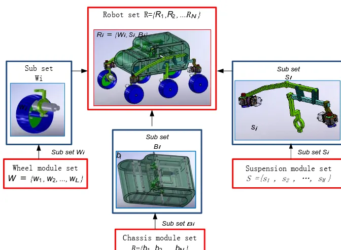
A typical wheeled mobile robot can be regarded as a multi-body system formed by three elemental modules, i.e. wheel module, suspension module and chassis (base) module. Each elemental module can be constructed by different mecha-nisms or rigid/articulated structures. In this paper, the differ-ent mechanisms forming differdiffer-ent types of wheeled modules, suspension modules and chassis (base) modules are defined in set forms as W= {w1, w2, . . ., wL},S= {s1, s2, . . ., sM}, and B= {b1, b2, . . ., bN}respectively, where the subscripts L,MandNare, respectively, the numbers of mechanisms or structures that can be selected to construct the wheel module, suspension module and chassis module.
To construct and design a particular wheeled mobile robot Ri, mono- or multi-type of mechanisms or structures in each of the three module sets can be chosen. As illustrated in Fig. 1, a wheeled robot, denoted as Ri, is the combination of the wheel module subset, the suspension module subset and the chassis module subset represented as
Ri= {{Wi, Si, Bi} |Wi⊂W,Si⊂SandBi ⊂B} (1)
where, the configurations Wi,Si andBi are subsets of the modular setsW,SandB, respectively.
The term “degree of choice” (DOC) denoted as DC is defined herein to represent the choices in each individual modular set. For example, if only one type of mechanism in the wheel module set is selected for constructing a spec-ified wheeled robot, we denote DC(Wi)=1, if two types of mechanisms in the wheel module set are chosen for con-structing a wheeled robot, it hasDC(Wi)=2, and ifltypes of mechanisms in the wheel module set that are chosen, it givesDC(Wi)=l, whereWi is a subset ofW denoting the ith combination of the wheel module. Similarly, the degree of choice (DOC) for the suspension module and chassis mod-ule can be expressed asDC(Si)=mandDC(Bi)=n, with Si andBi, standing for the subsets ofS andB, respectively,
representing theith combination of the suspension module and the chassis module.
Based on the above definition, the whole wheeled mobile robot set to be synthesized and designed in this paper can be expressed as
R= {R1, R2, . . ., Rk} (2)
wherekdenotes thekth combination of wheeled robots that can be synthesized and constructed.
2.2 Module based isomorphic and non-isomorphic combination
From the mechanism point of view, two kinematic chains or mechanisms are said to be isomorphic if they share the same topological structure (Tsai, 2000). In this paper, we ex-tend this concept for the combinations of the wheel module, suspension module and chassis module so as to synthesize and construct various types of structures for wheeled mobile robots.
Definition 1.For a wheeled robotRi= {Wi, Si, Bi}, if all
of its three modules, i.e. the wheel moduleWi, the suspen-sion module Si, and the chassis module Bi are configured with solo type of mechanisms/structures, which means the wheeled robot has all the three modules with degree of choice (DOC) of one asDC(Wi)=DC(Si)=DC(Bi)=1, and if the structure of a wheeled robot is synthesized by a combi-nation satisfying
DC(Wi)=1∧DC(Si)=1∧DC(Bi)=1 (3)
the combination mode is defined as anisomorphic combina-tion. Where the symbol “∧” stands for logical “and”.
Definition 2.For any robot Ri= {Wi, Si, Bi}, if at least
one of its modules has a degree of choice (DOC) that does not equal one as
DC(Wi)6=1∨DC(Si)6=1∨DC(Bi)6=1 (4)
the combination mode is defined as anon-isomorphic
com-bination. In Eq. (4), the symbol “∨” denotes logical “or”.
2.3 Structure synthesis of wheeled mobile robot
According to the above definition of isomorphic and non-isomorphic combinations, the modular-based structure de-sign of wheeled robots can be achieved through two kinds of basic synthesis modes, i.e. isomorphic-combination synthe-sis mode denoted as setRIand non-isomorphic-combination synthesis mode indicated as setRNI. Thus the whole set of wheeled robotsRthat can be synthesized and obtained is
R=RI∪RNI (5)
106 Z. Luo et al.: Module-based structure design of wheeled mobile robot
Springer, 2012, where a wide choice of types of wheels, suspensions, etc. are described.
There are several terms which in English I have never found (in the sense here used) like coined (1.introduction, line 2) Driving placidity (1.introduction, line 9), etc.
Sub set BI
Sub set SI
Sub set Wi
Wheel module set
W = {w1, w2 ,..., wL}
Suspension module set S ={s1 , s2 , …, sM }
Chassis module set
B={b1, b2,...,bN} Robot set R={R1,R2,...RN}
Ri = {Wi , Si , Bi }
Sub set Wi Sub set Si
wi
Sub set Bi
bi
[image:5.612.130.466.64.311.2]si
Figure 1.Module sets and Robot set.
2.3.1 Isomorphic-combination synthesis mode
According to the definition of isomorphic combination in Sect. 2.1, any robotRisynthesized based on the isomorphic-combination mode, which belongs toRI, can be written as
Ri= {{Wi, Si, Bi} | ∀Ri∈RI} (6)
Where each component module subset, i.e. Wi, Si and Bi must satisfy the condition presented in Eq. (3), there are three presuppositions provided: (a) the DOC of the wheel module setWisDC(W)=L, (b) the DOC of the suspension module setSisDC(S)=Mand (c) the DOC of the chassis module setBisDC(B)=N.
In this case, according to the above definition, the de-grees of choice for each Ri obtained from the isomorphic-combination synthesis mode can be computed as
DC(RI)=DC(W)×DC(S)×DC(B)=L×M×N (7)
Thus, the total number of wheeled robotsN(RI) that can be obtained by the isomorphic-combination synthesis mode is
N(RI)=L×M×N (8)
2.3.2 Non-isomorphic-combination synthesis mode
Similarly, we consider the set of wheeled robots RNI that can be obtained with non-isomorphic-combination synthesis mode. In this case, the three presuppositions presented in the
isomorphic-combination synthesis mode still hold such that DC(W)=L,DC(S)=MandDC(B)=N.
In this synthesis mode, the structure of a wheeled robotRi is described as
Ri= {{Wi, Si, Bi} | ∀Ri∈RNI} (9)
where the three component module subsetsWi,Si andBi must comply with the rule indicated in Eq. (4).
In this case, the degrees of choice of structures for a wheeled robotRi can be calculated as
DC(RNI)=
lmax
X
lmin CLl ×
mmax
X
mmin CMm×
nmax
X
nmin
CNn (10)
Where,Cpk denotes the k-combination of a set withp ele-ments, andl,mandnare, as aforementioned, respectively the numbers of wheel mechanisms/structures that are used to configure thel-combination wheel module subset such that DC(Wi)=l, the m-combination suspension module subset so thatDC(Si)=mand then-combination chassis module subset withDC(Bi)=n.
Since in most practical case each structure of a wheeled robot is formed by a suspension module subset of one mem-ber as well as a chassis module subset of one memmem-ber, such that in the most common design case, there exist mmax=
(a) (b) (c)
Figure 2.Exterior-planetary wheel.
into Eq. (10), it has
DC(RNI)=
lmax
X
l=2
CLl ×C1M×C1N=
lmax
X
l=2
CLl ×M×N (11)
Then, the total number of wheeled robots that can be attained in the non-isomorphic-combination synthesis mode is
N(RNI)=
lmax
X
l=2
CLl ×M×N (12)
In both Eqs. (11) and (12), there isl=DC(Wi)∈[2, L], and L=DC(W),M=DC(S) andN=DC(B).
3 Innovative design and characterization of elemental modules
The modular-based innovative synthesis and structure design of wheeled robots can be accomplished at two levels, i.e. ele-mental level and synthesis level. The eleele-mental module level aims to identify and design the three component modules of a wheeled robot including the wheel module, the suspen-sion module and the chassis module; and the synthesis level aims to get all possible and feasible kinds of design solu-tions based on the above the isomorphic-combination syn-thesis mode and the non-isomorphic-combination synsyn-thesis mode.
In this section, we focus on the creative design and char-acterization of the three elemental component modules.
3.1 Innovation and characterization of the wheel module
According to Haggart and Waydo (2008), different kinds of mechanisms/structures have been adapted to design the wheel module for constructing various wheeled robots. In this paper, two classical wheel structuresw1andw2are se-lected for structure design and synthesis, as listed in Table 1. The integration wheel, denoted asw1which is constructed by enveloped structure, is a simple, compact and reliable de-sign scheme for planetary robot. However, it is hard for this kind of wheel to overwhelm obstacle that is higher than half of its radius. The exterior-planetary wheelw2, consisting of three evenly distributed wheels driven by a central geared wheel, can conquer high obstacle like stairs. As indicated in
(a) (b) (c)
Figure 3.Planetary-tracked wheel and its working phases.
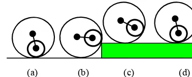
(a) (b) (c) (d)
Figure 4.Interior-planetary wheel and its working phases.
Fig. 2, when it encounters an obstacle, the wheel frame turns around and cross the obstacle. This kind of wheel has excel-lent obstacle-crossing capability and ground adaptability, but due to the multiple contact points between the wheel and the ground, steering of robot with this kind of wheels is ineffi-cient, which mainly relies on the differential motion of the wheels.
By reflecting on the advantages and disadvantages of the integration wheel and the exterior-planetary wheel, this paper proposes two novel wheel modules, i.e. the planetary-tracked wheelw3and the interior-planetary wheelw4(see Table 1). The planetary-tracked wheel modulew3has the advantages of both the tracked and exterior planetary wheels. Using this structure, when the obstacle is small, the wheel negotiates obstacle like common tracked robot, as shown in Fig. 3a; in case the wheel encounters a big obstacle as the green block shown in Fig. 3c, it turns around its axle and negotiate the obstacle to cross over, as shown in Fig. 3b.
The interior-planetary wheelw4is a novel one constructed based on interior planetary system, as shown in Fig. 4, it has excellent obstacle-crossing capability and flexible steer-ing ability. When the exterior wheel hits on an obstacle (see Fig. 4a and b), the interior geared wheel continues to climb and once the mass centre of the interior wheel is higher than the obstacle, the whole wheel gains the capability to cross the obstacle as illustrated in Fig. 4c and d.
[image:6.612.330.519.193.269.2]108 Z. Luo et al.: Module-based structure design of wheeled mobile robot
Table 1.Four types of wheel modules.
Module name Illustrative diagram Description Integration wheelw1
3 2 1
Integrating driving, steering and sensor in (classical wheel module) the volume of wheel, this kind of wheel
is utilized in the Rocky series robots, Krotkov et al. (1994).
Exterior planetary wheelw2
3 2
1 Excellent obstacle-crossing capability and
(classical wheel module) ground adaptability. But robot steering can only be realized by differential speeds of wheels.
Planetary tracked wheelw3
2 3 4
1 Combining the advantages of tacked and (novel wheel module) exterior planetary wheel, it has better ground
adaptability and obstacle-crossing ability comparing tow1andw2.
Interior planetary wheelw4
2 3
1 Excellent obstacle-crossing capability
(novel wheel module) and flexible steering ability. However, its motion control is more complex than
w1,w2,w3due to the interior planetary gears.
3.2 Identification and innovation of the suspension module
The typical suspensions used in wheeled robots are active or adaptive. In this paper, in order to synthesize and construct different types of wheeled robots, three classical suspension structuress1,s2ands3are selected, and two novel structures are proposed as listed in Table 2.
The two-wheeled rigid suspensions1is proved to be a sim-ple, compact and reliable choice for the four-wheeled robot (Krotkov et al., 1994). However, it can only implement un-dulation equalization once by the rotation of whole suspen-sion, it cannot efficiently improve the motion smoothness and obstacle negotiation. The three-wheeled rocker-boogie suspension s2 has been proved to be a successful suspen-sion for the Mars exploration rover (Huntsberger et al., 2002; Richard, 2005), compared to suspension s1, it can imple-ment undulation equalization twice by the rotation of primary and secondary rockers. Similarly, the four-wheeled rocker-boogie suspensions3can implement twice undulation equal-ization by the rotation of primary and secondary rockers. The schemes of these three suspensions are shown in Fig. 5.
In addition, two kinds of new suspension structures are put forward in this paper, one is the parallel slider-crank suspen-sion (Shang et al., 2006a, b)s4 and the other is a four-bar-linkage-integrated suspensions5, as listed in Table 2. For the parallel slider-crank suspension, the wheels can overcome obstacle by the slider’s linear motion relative to the frame, which can reduce the vertical motion of robot and keep all wheels contact with the surface when it travels on bumpy terrain, as illustrated in Fig. 6.
The four-bar-linkage-integrated suspensions5is an inno-vative variation of the rocker-boogie suspension which
re-(a) Rigid suspension
(b) Rocker-bogie suspension
(c) Four-wheeled rocker-bogie suspension
Figure 5.Three typical suspension modules.
Figure 6.A parallel slider-crank suspension.
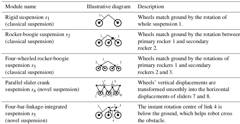
Table 2.Five types of suspension structures.
Module name Illustrative diagram Description Rigid suspensions1
whole suspension 1
2)
1
Wheels match ground by the rotation of (classical suspension) whole suspension 1.
Rocker-boogie suspensions2 s2) 1 2 Wheels match ground by the rotation between
(classical suspension) primary rocker 1 and secondary rocker 2.
Four-wheeled rocker-boogie
2
3 1 Wheels match ground by the rotations of
suspensions3 primary rockers 1 and secondary
(classical suspension) rockers 2 and 3. Parallel slider crank
5 3
2 4 6
1
7 8 Wheels’ vertical displacements are
suspensions4(novel suspension) transformed smoothly into the horizontal
displacements of sliders 7 and 8. Four-bar-linkage-integrated
4
1 2 3 The instant rotation centre of link 4 is
suspensions5 below the ground, which helps robot cross
(novel suspension) the obstacle.
Figure 7.A four-Bar-linkage-integrated suspension.
The above five suspension structures compose a suspen-sion module set S= {s1, s2, s3, s4, s5}, as listed in Table 2, for constructing wheeled robots in Sect. 4.
3.3 Design and identification of the chassis module
Five types of rigid or articulated structures are selected in this paper to form a chassis module set for synthesis and design of wheeled robots, denoted asB= {b1, b2, b3, b4, b5}. They are the rigid-shaft chassisb1, the elastic-shaft chassisb2, the differential-geared chassis b3, the right-and-left segmented chassisb4and the fore-and-aft segmented chassisb5as listed and illustrated in Table 3.
The elastic shaft chassisb2, as shown in Table 3, consists of two symmetric elastic shafts 1 and a frame 2. One end of the elastic shaft is connected to the frame end, and the other end is connected to a corresponding suspension such that the two suspensions can rotate independently relative to the frame.
The differential chassisb3, as shown in the third row of Ta-ble 3, consists of a pair of coaxial pinions denoted as 1 and 2, a gear 3 and a frame 4, this mechanism makes it possible for the two suspensions connected to shafts of bevel gears 1 and 2 to rotate in opposite directions without turning the frame. It is interesting to note that, if one of the suspension is held stationary and the other one is free to rotate, the frame can turn at the half speed of the suspension. This characteristic
helps to achieve motion smoothness when the robot crosses an obstacle.
The right-and-left segmented chassisb4, as shown in the fourth row of Table 3, essentially contains a left segmented chassis 1, a right segmented chassis 2 and a shaft 3. Com-pared to the differential chassis b3, the suspensions con-nected to this kind of chassis turn together with the seg-mented chassis around shaft 3 which helps the suspensions match the change of terrains.
4 Module-based structure synthesis of reconfigurable wheeled robots
The design theory of vehicles demonstrates that the vehicle mobility and complexity increase with the increase of wheel number; once the number of wheels is determined, the design of suspension and wheel mechanisms/structures follows. Ac-cording to the state-of-the-art of wheeled robots, researchers mainly adopt 4, 6 and 8 wheels. Hence, considering the prac-tical applications, this paper mainly focuses on synthesis of the 4-, 6- and 8-wheeled robots; the method proposed here can be extended to the synthesis ofn-wheeled robots.
4.1 Isomorphic-combination synthesis and construction of wheeled robots
4.1.1 Synthesis of reconfigurable four-wheeled robots
110 Z. Luo et al.: Module-based structure design of wheeled mobile robot
Table 3.Five selected chassis modules.
Module name Illustrative diagram Description
Rigid-shaft chassisb1 Left and right suspensions are fixed with
chassis through a rigid shaft 1, this is a rigid chassis.
Elastic-shaft chassisb2
3
2 1
Left and right suspensions are connected to chassis through an elastic shaft 1, therefore the suspensions can rotate relatively to chassis through the torsion of elastic shaft. Differential chassisb3 Left and right suspensions are connected
to chassis through a differential gear shaft. Therefore, the chassis’s pitch is half of that of the suspensions. It provides a good traverse smoothness.
Right-and-left segmented
3
2 1
Suspensions are fixed to right and left chassisb4 segment chassis 1 and 2 respectively,
while the segmented chassis can rotate relatively around shaft 3.
Fore-and-aft segmented
3 1
2
Suspensions and wheels are fixed to chassisb5 fore-and-aft chassis respectively, while
the segmented chassis can rotate relatively around shaft 3.
In practical design, for a four-wheeled robot, the suspen-sion and chassis can be reconfigured in the layouts of and-right or fore-and-aft mode. Here we consider the left-and-right mode first. According to Eq. (7), the degrees of choice of the four-wheeled robots that can be synthesized with the chassis module setBis
DC(RI4−1)=DC(W)×DC(S)×DC(B)=4×1×5=20 (13)
As aforementioned,DCstands for degrees of choice.RI4−1 denotes the set of wheeled robot with subscripts I stand-ing for isomorphic-combination synthesis, “4” denotstand-ing four wheels and “1” standing for the left-and right mode.
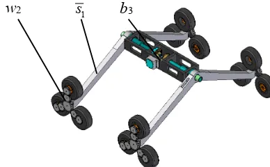
An example structure, i.e. w2-b3-s1 for a four-wheeled robot with suspension of left-and-right layout is illustrated in Fig. 8, the planetary-tracked wheelsw2and the rigid sus-pensionss1are integrated on both the left and right sides of a differential chassisb3.
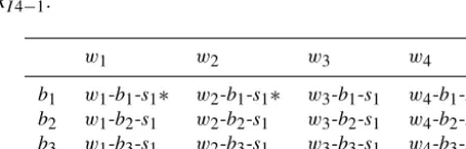
In this layout mode, as listed in Table 4, by adopting in-tegrated chassis modules includingb1,b2andb3, and wheel modulesw1,w2,w3andw4, 12 design schemes can be ob-tained. In the table, schemes w2-b1-s1∗ andw1-b1-s1∗ are existing schemes, and the rest 10 designs are new ones; while by adopting segmented chassis in which case onlyb4is fea-sible, 4 more design schemes can be achieved as indicated in the last low of Table 4 and they are all new structures. In the table and hereafter, the scheme with superscript “*” indicates
[image:9.612.327.528.374.491.2]w
3b
3s
1Figure 8.Typew3-b3-s1structure for a four-wheeled robot in
[image:9.612.320.535.570.638.2]left-and-right layout.
Table 4.Structures of four-wheeled robots in left-and-right layout
RI4−1.
w1 w2 w3 w4
b1 w1-b1-s1∗ w2-b1-s1∗ w3-b1-s1 w4-b1-s1
b2 w1-b2-s1 w2-b2-s1 w3-b2-s1 w4-b2-s1
b3 w1-b3-s1 w2-b3-s1 w3-b3-s1 w4-b3-s1
b4 w1-b4-s1 w2-b4-s1 w3-b4-s1 w4-b4-s1
that it is an existing scheme that can be found in existing lit-erature.
w
2s
1b
3Figure 9.Typew2-b3-s1structure for a four-wheeled robot in
[image:10.612.358.506.68.186.2]fore-and-aft layout.
Table 5.Structures for four-wheeled robots in fore-and-aft layout
RI4−2.
w1 w2 w3 w4
b1 w1-b1-s+1 w2-b1-s1+ w3-b1-s1+ w4-b1-s+1
b2 w1-b2-s1 w2-b2-s1 w3-b2-s1 w4-b2-s1
b3 w1-b3-s1 w2-b3-s1 w3-b3-s1 w4-b3-s1
b4 w1-b4-s+1 w2-b4-s1+ w3-b4-s1+ w4-b4-s+1
b5 w1-b5-s1∗ w2-b5-s1 w3-b5-s1 w4-b5-s1
which only two are existed, and the remaining 14 are new schemes.
Further, by reconfiguring the suspension system, struc-tures of wheeled robots with suspensions in the fore-and-aft layout can be synthesized and one example, i.e. w2-b3
-s1is illustrated in Fig. 9, which has four exterior-planetary-tracked wheelsw2and two rigid suspensionss1of fore-and-aft layout assembled in a differential chassisb3.
In this layout mode, 20 structures denoted asDC(RI4−2) can be synthesized as listed in Table 5. By adopting inte-grated body modules including b1, b2 and b3, and wheel modules including w1,w2,w3 andw4, 12 design schemes can be obtained. Considering the 4 design schemes listed in the first row of Table 5 (denoted with superscript “+” in the end) that are composed of the suspension modules1, the rigid chassis module b1and all of the four wheel modules, they are functionally the same as the four schemes that are listed in the first row of Table 4. Thus 8 types of design schemes are actually attained and they are all new. Subsequently, by adopting the segmented chassis including modulesb4andb5, 8 more design schemes can be synthesized in whichw1-b4
-s1 andw1-b5-s1are existing schemes, considering the four schemes including fore-and aft layout of chassisb4(denoted with superscript “+” in the end) is logically same as the four design schemes including chassisb5, and hence 3 of them are new.
From the above analysis, in isomorphic-combination syn-thesis mode 28 structures for the four-wheeled robot can be synthesized in which 25 of them are new. Therefore, the
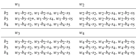
[image:10.612.55.279.268.350.2]de-w
1b
3s
5Figure 10.Typew1-b3-s5structure for a six-wheeled robot.
grees of choice of structures for four-wheeled robot synthe-sized based on the isomorphic-combination synthesis mode is
DC(RI4)=DC(RI4−1)+DC(RI4−2)−4=16+20−8=28 (14) where,RI4 denote the structure of four-wheeled robot ob-tained in the isomorphic-combination synthesis mode. And thus using Eq. (8), the number of structures of the robots syn-thesized in this section isN(RI4)=DC(RI4)=28.
4.1.2 Synthesis of six-wheeled robots
In order to synthesize six-wheeled robots, in isomorphic-combination synthesis mode, component modules consid-ered are: (a) the wheel module subsetW= {w1, w2, w3, w4}, (b) the suspension module subsetS2= {s2, s4, s5}, and (c) the integrated chassis module setB3= {b2, b3, b4}. According to Eq. (7), degrees of choice of six-wheeled robot that can be synthesized is
DC(RI6)=DC(W)×DC(S2)×DC(B3)=4×3×3=36 (15) The structure of an example six-wheeled robot that is syn-thesized with the isomorphic-combination synthesis mode by integrating an integration wheel modulew1, a four-bar link-age integrated suspensions5and a differential chassisb3is il-lustrated in Fig. 10. This is a typew1-b3-s5structure in which the four-bar linkage integrated suspension helps realize twice undulations when crossing obstacles.
Referring to Eq. (8), we know that there are N(RI6)= DC(RI6)=36 design schemes that can be synthesized in this category. These structures are listed in Table 6, in which only 1 design scheme (w1-b3-s2∗) can be found in the literature (see Table 13) and the others are all new.
4.1.3 Synthesis of eight-wheeled robots
112 Z. Luo et al.: Module-based structure design of wheeled mobile robot
Table 6.Structures for six-wheeled robotsRI6.
w1 w2
b2 w1-b2-s2,w1-b2-s4,w1-b2-s5 w2-b2-s2,w2-b2-s4,w2-b2-s5
b3 w1-b3-s2∗,w1-b3-s4,w1-b3-s5 w2-b3-s2,w2-b3-s4,w2-b3-s5
b4 w1-b4-s2,w1-b4-s4,w1-b4-s5 w2-b4-s2,w2-b4-s4,w2-b4-s5
w3 w4
b2 w3-b2-s2,w3-b2-s4,w3-b2-s5 w4-b2-s2,w4-b2-s4,w4-b2-s5
b3 w3-b3-s2,w3-b3-s4,w3-b3-s5 w4-b3-s2,w4-b3-s4,w4-b3-s5
[image:11.612.345.512.226.366.2]b4 w3-b4-s2,w3-b4-s4,w3-b4-s5 w4-b4-s2,w4-b4-s4,w4-b4-s5
Table 7.Structures for eight-wheeled robotsRI8.
w1 w2 w3 w4
b2 w1-b2-s3 w2-b2-s3 w3-b2-s3 w4-b2-s3
b3 w1-b3-s3∗ w2-b3-s3 w3-b3-s3 w4-b3-s3
b4 w1-b4-s3 w2-b4-s3 w3-b4-s3 w4-b4-s3
case, the whole wheel module setW= {w1, w2, w3, w4}and the integrated chassis module subset B3= {b2, b3, b4} are used for the synthesis. However, only the suspension mod-ule subsetS3= {s3}can be used for this synthesis. Thus, the degrees of choice of the wheel, suspension and chassis mod-ules areDC(W)=4,DC(S3)=1 andDC(B3)=3, respec-tively. Substituting these into Eqs. (7) and (8), the degrees of choice i.e. the number of eight-wheeled robots that can be synthesized is
N(RI8)=DC(RI8)=DC(W)×DC(S3)×DC(B3)
=4×1×3=12 (16)
Hence, 12 design schemes can be attained in this synthesis scheme. They are listed in Table 7 and one of the schemes, i.e.w1-b3-s3∗can be found in the literature, thus 11 of them are new schemes. An example of the structure, i.e. type w4-b4-s3for an eight-wheeled rovers that is constructed by combining an interior-planetary wheel module w4, a four-wheeled rocker-bogie suspension modules3and a right-and-left segmented chassis moduleb4is illustrated in Fig. 10.
Hence, based on the isomorphic-combination approach, totally 76 types of structures for wheeled robots are synthe-sized as
N(RI)=DC(RI)=DC(RI4)+DC(RI6)+DC(RI8)
=28+36+12=76 (17)
In these 76 types, 5 of them can be found in the literature proposed by the other researchers and 71 of them are novel structures.
w
4s
3b
4Figure 11.Typew4-b4-s3structure of an eight-wheeled robot.
4.2 Non-isomorphic-combination synthesis and enumeration
Section 4.1 presents the synthesis of wheeled robots based on the isomorphic-combination mode and 76 types of struc-tures for wheeled robot have been generated. In this sec-tion, we focus on the synthesis and enumeration of struc-tures for the wheeled robots by using the non-isomorphic-combination synthesis mode. As discussed in Sect. 2, in the non-isomorphic-combination synthesis mode, for each struc-ture to be synthesized, there must be at least two different types of wheel modules involved.
4.2.1 Synthesis of structures for four-wheeled robots
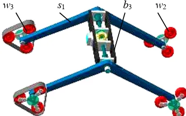
[image:11.612.63.268.242.299.2]synthe-w
3s
1b
3w
2Figure 12.A typew23-b3-s1four-wheeled robot generated by
non-isomorphic combination.
sis mode is
DC00(RNI4−1)=
C42+C43+C44×M1×N1=11×1×3=33 (18) Where,M1=DC(S1)=1 andN1=DC(B1)=3.
However, in practical applications, in order to achieve bet-ter balance and locomotion performance, symmetric layout is adopted in the four-wheeled robot design such that the cases of integrating a wheel module subsetWi that contains three or four different types of wheel mechanisms/structures will not be considered. Therefore, in this section, in order to syn-thesize feasible four-wheeled robot, the maximum number of mechanisms/structures involved in one wheel module sub-set isl1max=DC(Wi)1max=2 such that the combinations of wheel modules in the cases C43 andC44 are not taken into account. Further, similar to the isomorphic-combination syn-thesis, structure of a wheeled robot with a rigid suspension s1can be reconfigured in both left-and-right layout and fore-and-aft layout. Hence, considering the above two additional points, by revising Eq. (18), the reasonable degrees of choice of structures for a four-wheeled robot that can be synthesized in this category is
DC0 (RNI4−1)=2×C42×M1×N1=2×6×1×3=36 (19)
In these 36 structures, 18 of them are constructed with sus-pension in the right-and left layout and the other 18 types are generated with suspension in the fore-and-aft layout. All the 18 design schemes in the right-and-left layout are novel ones and they are listed in Table 8. In the table,wab denotes a wheel module subset Wi containing both wheel mechanisms/structures wa andwb with a < band {a, b} ∈
{1,2,3,4}.
Figure 12 shows the structure of a typew23-b3-s1scheme four-wheeled robot, that is synthesized in this category. It contains two wheel modules, i.e. one exterior-planetary wheel modulew2 and one planetary-tracked wheel module w3, a rigid suspensions1and a differential chassisb3.
Furthermore, the 18 structures in the fore-and-aft layout are listed in Table 9. In the table, s denotes the
suspen-sion module that is configured in the fore-and-aft format. In these 18 design schemes, 6 of them, as shown in the first row of Table 9 with symbol “+” in the superscript, which are generated by combining the suspension modules1, the rigid body b1 and 2-combination of the wheel module set W= {w1, w2, w3, w4}are functionally the same as those 6 schemes listed in the first row of Table 8 with the suspen-sion in the left-and-right layout. Thus, there are 12 design schemes obtained in this category and they are all novel ones. From Tables 8 and 9, it can be found that the actually de-grees of choice of the structures for the four-wheeled space-exploring robot that adopts the integrated chassis module is
DC(RNI4-1)=DC0 (RNI4-1)−6=36−6=30 (20)
and they are all new schemes.
In addition, considering those design schemes that adopt the segmented-body module subsetB2= {b4, b5}, the addi-tional degrees of choice of the structures for a four-wheeled mobile robot that are synthesized in this non-isomorphic-combination synthesis mode is
DC(RNI4−2)=C24×M1×N2=6×1×2=12 (21)
whereN2=DC(B2)=2.
Referring to Eq. (12) we get 12 more types of design schemes, they are all new structures and are listed in Ta-ble 10.
Therefore, including all the structures listed in Tables 8, 9 and 10, the total number of structures for the four-wheeled space-exploring robots synthesized using the non-isomorphic-combination mode is
N(RNI4)=DC(RNI4−1)+DC(RNI4−2)=30+12=42 (22)
All these 42 types are new and feasible design schemes.
4.2.2 Synthesis of structures for six-wheeled robot
114 Z. Luo et al.: Module-based structure design of wheeled mobile robot
Table 8.Structures for four-wheeled robotsRNI4−1in left-and-right layout.
w12 w13 w14 w23 w24 w34
b1 w12-b1-s1 w13-b1-s1 w14-b1-s1 w23-b1-s1 w24-b1-s1 w34-b1-s1
b2 w12-b2-s1 w13-b2-s1 w14-b2-s1 w23-b2-s1 w24-b2-s1 w34-b2-s1
[image:13.612.60.516.179.403.2]b3 w12-b3-s1 w13-b3-s1 w14-b3-s1 w23-b3-s1 w24-b3-s1 w34-b3-s1
Table 9.Structures for four-wheeled robotsRNI4−1in fore-and-aft layout.
w12 w13 w14 w23 w24 w34
b1 w12-b1-s+1 w13-b1-s+1 w14-b1-s1+ w23-b1-s+1 w24-b1-s+1 w34-b1-s+1
b2 w12-b2-s1 w13-b2-s1 w14-b2-s1 w23-b2-s1 w24-b2-s1 w34-b2-s1
b3 w12-b3-s1 w13-b3-s1 w14-b3-s1 w23-b3-s1 w24-b3-s1 w34-b3-s1
w
3s
2b
3w
4 [image:13.612.315.525.199.403.2]w
3s
2b
3w
4Figure 13.A typew34-b3-s2six-wheeled robot generated by
non-isomorphic combination,
non-isomorphic-combination synthesis mode is
DC(RNI6)=
l2max
X
l=2
CLl ×DC(S2)×DC(B1)
=C42+C43×3×3=90 (23)
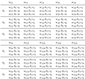
Therefore, according to the relation between Eqs. (11) and (12), there are totallyN(RNI6)=DC(RNI6)=90 structures that can be obtained in this synthesis category and all these 90 structures are new design schemes. The results are listed in Table 11. In Table 11, wab denotes a member of a wheel module subset Wi= {wa, wb} containing both wheel mechanisms/structures wa and wb with a < b and
{a, b} ∈ {1,2,3,4}, andwabc witha < b < c and{a, b, c} ∈
{1,2,3,4} denotes an element of a wheel module subset
Wj = {wa, wb, wc}that is composed of three wheel mech-anisms/structureswa,wbandwc.
An example of the structure for a six-wheeled space-exploring robot, i.e. type w34-b3-s2synthesized in the sec-tion is shown in Fig. 13. It is composed of four planetary-tracked wheels w3, two interior-planetary wheels w4, two rocker-boogie suspensionss2and a differential chassisb3.
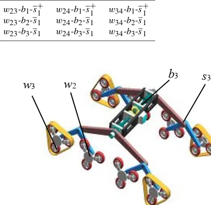
w
3w
2b
3s
3Figure 14.A typew23-b3-s3 eight-wheeled robot generated by
non-isomorphic combination.
4.2.3 Structure synthesis of eight-wheeled robot
Similarly, by using the component modules provided in Sect. 3 including (a) the wheel module set W= {w1, w2, w3, w4}, (b) the suspension module subset S3= {s3} and (c) the integrated-chassis module subset B1= {b1, b2, b3}, the structures for eight-wheeled robots can also be generated based on the non-isomorphic-combination syn-thesis mode. Figure 14 shows a structure of an eight-wheeled robot that is synthesized in this section. It is typew23-b3-s3 scheme consisting of four exterior-planetary wheelsw2, four planetary-tracked wheelsw3, a rocker-bogie suspension s3 and a differential chassisb3.
Table 10.Structures for four-wheeled robotsRNI4−2.
w12 w13 w14 w23 w24 w34
b4 w12-b4-s1 w13-b4-s1 w14-b4-s1 w23-b4-s1 w24-b4-s1 w34-b4-s1
[image:14.612.157.441.171.437.2]b5 w12-b5-s1 w13-b5-s1 w14-b5-s1 w23-b5-s1 w24-b5-s1 w34-b5-s1
Table 11.Structures for six-wheeled robotsRNI6.
w12 w13 w14 w23 w24
b1
w12-b1-s2 w13-b1-s2 w14-b1-s2 w23-b1-s2 w24-b1-s2
w12-b1-s4 w13-b1-s4 w14-b1-s4 w23-b1-s4 w24-b1-s4
w12-b1-s5 w13-b1-s5 w14-b1-s5 w23-b1-s5 w24-b1-s5
b2
w12-b2-s2 w13-b2-s2 w14-b2-s2 w23-b2-s2 w24-b2-s2
w12-b2-s4 w13-b2-s4 w14-b2-s4 w23-b2-s4 w24-b2-s4
w12-b2-s5 w13-b2-s5 w14-b2-s5 w23-b2-s5 w24-b2-s5
b3
w12-b3-s2 w13-b3-s2 w14-b3-s2 w23-b3-s2 w24-b3-s2
w12-b3-s4 w13-b3-s4 w14-b3-s4 w23-b3-s4 w24-b3-s4
w12-b3-s5 w13-b3-s5 w14-b3-s5 w23-b3-s5 w24-b3-s5
w34 w123 w124 w134 w234
b1
w34-b1-s2 w123-b1-s2 w124-b1-s2 w134-b1-s2 w234-b1-s2
w34-b1-s4 w123-b1-s4 w124-b1-s4 w134-b1-s4 w234-b1-s4
w34-b1-s5 w123-b1-s5 w124-b1-s5 w134-b1-s5 w234-b1-s5
b2
w34-b2-s2 w123-b2-s2 w124-b2-s2 w134-b2-s2 w234-b2-s2
w34-b2-s4 w123-b2-s4 w124-b2-s4 w134-b2-s4 w234-b2-s4
w34-b2-s5 w123-b2-s5 w124-b2-s5 w134-b2-s5 w234-b2-s5
b3
w34-b3-s2 w123-b3-s2 w124-b3-s2 w134-b3-s2 w234-b3-s2
w34-b3-s4 w123-b3-s4 w124-b3-s4 w134-b3-s4 w234-b3-s4
w34-b3-s5 w123-b3-s5 w124-b3-s5 w134-b3-s5 w234-b3-s5
DC(RNI8)=
L
X
l=2
CLl ×M3×N1
=
C42+C43+C44
×1×3=33 (24)
Where, L=DC(W)=4, M3=DC(S3)=1 andN1=3 is the same as that in Eq. (18).
Therefore, according the Eq. (12), there are N(RNI8)=
DC(RNI8)=33 structures attained in this section for gen-erating eight-wheeled robots and they are all new design schemes; the results are listed in Table 12.
Hence, summarizing all the structures obtained from Ta-bles 8 to 12, the total number of structures for wheeled robots that are synthesized based on the non-isomorphic-combination synthesis mode can be calculated as
N(RNI)=DC(RNI)=N(RNI4)+N(RNI6)+N(RNI8)
=42+90+33=165 (25)
This also implies that there are 165 non-isomorphic struc-ture schemes to be chosen for designing a feasible desired
wheeled robot based on the specific functions required. All these 165 schemes are new ones.
As a result, using structure synthesis for wheeled robots with isomorphic and non-isomorphic module combinations, the number of structures for wheeled robot achieved in this paper is
N(R)=N(RI)+N(RNI)=76+165=241 (26)
116 Z. Luo et al.: Module-based structure design of wheeled mobile robot
Table 12.Structures for eight-wheeled robotsRNI8.
w12 w13 w14 w23 w24 w34
b1 w12-b1-s3 w13-b1-s3 w14-b1-s3 w23-b1-s3 w24-b1-s3 w34-b1-s3
b2 w12-b2-s3 w13-b2-s3 w14-b2-s3 w23-b2-s3 w24-b2-s3 w34-b2-s3
b3 w12-b3-s3 w13-b3-s3 w14-b3-s3 w23-b3-s3 w24-b3-s3 w34-b3-s3
w123 w124 w134 w234 w1234 –
b1 w123-b1-s3 w124-b1-s3 w134-b1-s3 w234-b1-s3 w1234-b1-s3 –
b2 w123-b2-s3 w124-b2-s3 w134-b2-s3 w234-b2-s3 w1234-b2-s3 –
[image:15.612.85.511.235.290.2]b3 w123-b3-s3 w124-b3-s3 w134-b3-s3 w234-b3-s3 w1234-b3-s3 –
Table 13.Existing structures.
Existing robot w1-b1-s1 w2-b1-s1 w1-b5-s1 w1-b3-s2 w1-b3-s3
Sources Apollo 15 Lunar rover, see
Gao et al. (2005) Widely used insegmented vehi-cle
Sojourner
Cu-riosity YUTU Lunarsee Eom et al.robot, (2014)
5 Simulation and prototype evaluation
In this section, feasibility of the structures for wheeled robots proposed in Sect. 4 are evaluated based on virtual prototypes, mathematical models and physical prototype to provide in-formation for product development and the subsequent ex-perimental studies.
5.1 Simulation based on virtual prototype
The virtual prototype technology provides an efficient and intuitive tool that can be used to build up the entire product model digitally, and subsequently to simulate and analyse the performance of the proposed product virtually in different kinds of working conditions. It helps to assess performance of the product and provide suggestions for optimising the de-sign and hence improving the produce functions.
In this paper, a software platform is developed by integrat-ing the ADAMS® software with the control package pro-vided by Matlab®/Simulink®for constructing virtual mod-els of the structures of wheeled robots synthesized in Sect. 4 and also simulating and evaluating their functions and per-formance. The platform we developed has the functions of supporting module definition, processing module combina-tion, implementing performance evaluation and conducting design optimization. The flow chart diagram of the proce-dures of the software platform is shown in Fig. 15.
In order to simulate and evaluate a specified design of a wheeled robot, by following the procedures illustrated in Fig. 15, we firstly build the dynamic and control models of all component modules based on the dynamics pack-age in the ADMAS system and the control packpack-age in the Matlab/Simulink system, respectively. Then we combine component modules into the integrated virtual robot
proto-Module design
Module combination Isomorphic combination
&
Non-isomorphic combination cccCombination)
Simulation, evaluation and optimization
Adaptability assessment
Placidity assessment
Obstacle-crossing assessment Dynamics
modeling (ADAMS)
Control modeling (Matlab/simulink)
Virtual terrain Virtual prototype of robot Wheel modules
(w1,w2,w3,w4)
Chassis modules (b1,b2,b3,b4,b5)
Suspension modules (s1,s2,s3,s4,s5)
Robot evaluation Module combination
[image:15.612.309.545.311.530.2]Design
Figure 15. Procedures for virtual simulation and evaluation of
space rover.
type. Thereafter, a predefined virtual terrain environment is used to test the mobility of the robot, including capacity of geometric-passing, obstacle-crossing, anti-capsizal, smooth-ride, etc. Finally, we can optimize the parameters of the robot and make decision on the choice of design schemes.
the wheel is 80 mm, the distance between the two adjacent wheels is 300 mm, and the width of the robot is 450 mm. In the virtual prototype, material properties for each component were properly assigned and information for terrain environ-ment was defined.
In the simulation, the robot can climb a slope of 35◦, as shown in Fig. 16a, and can cross over various typical blocks and craters with heights of 60 mm facilely, as shown in Fig. 16b. In the evaluation of driving smoothness, the grav-ity height of the front wheel, middle wheel, rear wheel are 60 mm (see Fig. 16d) when the robot climbs a 60 mm height obstacle, while the gravity height change of chassis is nearly 35 mm (see Fig. 16d), which is much smaller than that of the six wheels, this validate that the robot has excellent driv-ing smoothness. Fig. 16e shows the contact forces of the six wheels, Fig. 16f shows the contact force of the front wheel, by comparing Fig. 16e with Fig. 16f, we found that the con-tact forces of the six wheels are relatively homogeneous, this validates the force smoothness performance of the proposed robot.
5.2 Mathematical models for traverse performance evaluation
The vehicle traversing theory shows that the traverse ability and versatility of a vehicle are enhanced with the increase of wheel number. However, once the number of wheels is determined, the design of the suspension system associated with the wheel system becomes important and the feature of the whole mechanical system needs to be evaluated. Thus, in order to provide better solutions for practical space-exploring rover design, the following desired features are considered in the structure evaluation:
1. Ground adaptability. As a space rover, its wheels must have excellent adaptability to follow the contours of dif-ferent kinds of terrains. The contact forces between the wheels and the terrain are expected to be smooth, so as to obtain the maximal ground adhesion forces and pre-vent single wheel from getting stuck in the ground. In order to get the maximal ground adhesion forces, self-adaptability model of a single wheel can be formulated as
Vs(t)=Fc(t)−Ff
Ff (27)
Where,Fc(t) is the wheel-ground contact force at time t,Ffis the wheel-ground contact force on a flat terrain, and Vs(t) is the coefficient of self-adaptability of the wheel at timet.
2. Driving smoothness. Considering autonomous naviga-tion and instrument safety, a space rover should drive
placidly. Driving smoothness is mainly assessed based on the varying range and frequency of the pitch angle, the roll angle and the height of the rover chassis cen-tre. The varying range is determined by the suspension structure; while the varying frequency is influenced by the control characteristic of autonomous navigation. Es-pecially, the variation of the height of the rover chas-sis centre has a significant effect on driving smooth-ness. The average values of the height of body centre h(t), the pitch angle α(t) and the roll angleβ(t), can be used for evaluating driving smoothness of the space-exploring wheeled robots. The disperse degree ofh(t) can be evaluated by its mean square, which is expressed as
σh2(t)=E{h(t)−h2} (28)
where,σh2(t) denotes the mean square ofh(t),E de-notes the arithmetic of average value, andhis the av-erage value ofh(t). The same function can be used for measuring the pitch angleαand roll angleβ, which can be expressed asσα2(t) andσβ2(t), respectively.
3. Obstacle-crossing capability. It is determined by the suspension system and the wheels. The suspension sys-tem distributes the load of weight equally to all the wheels. If the suspension systems are similar, the di-ameter, the width and the spiral fin of the wheel become decisive factors. If the parameters of mass and power are determined, the margin of obstacle-crossing capa-bility can be reflected by the height of the obstacleh0 that the rover can cross over, The larger heighth0is, the better obstacle-crossing capability of the robot has.
5.3 Physical prototype development and tests
Based on the simulation and evaluation results obtained in the software platform, optimal and detailed designs of several types of wheeled robots were conducted and physical proto-types of the modules and robots were fabricated, assembled and integrated with low-level control system, vision system and sensors.
118 Z. Luo et al.: Module-based structure design of wheeled mobile robot
Figure 16.Simulation and evaluation of a six-wheeled rover in virtual environment.
(a) Four-wheeledw3-b3-s1
3
(b) Six-wheeledw4-b3-s2
3
(c) Six-wheeledw1-b3-s5
Figure 17.Prototypes of three types of wheeled robots.
that all these three robots have excellent ground adaptability, driving smoothness and obstacle crossing capability. Taking the six wheeled robot (w1-b3-s5) as an example, as shown in Fig. 18, this new robot has better smoothness compared with
classic rokie-bogie suspension robot (w1-b3-s2) when both conquer the same obstacle with the height of 60 mm.
[image:17.612.101.495.502.610.2]Minor comments:
Minor comments:
(a) Six-wheeledw1-b3-s20 1 2 3 4 5 6
-20 0 20 40 60 80
time t/s
he
ig
ht
p
/m
m
w1-b3-s2 w1-b3-s5
(b) Six-wheeledw1-b3-s5
Minor comments:
0 1 2 3 4 5 6
-20 0 20 40 60 80
time t s
he
ig
ht
p
m
m
w1-b3-s2 w1-b3-s5
(c) Driving smoothness
-1
[image:18.612.52.550.72.179.2]-1
Figure 18.Performance evaluation of typew1-b3-s5six-wheeled robot.
(a) Slope climbing (b) Running on ground
(d) Front wheel crossing obstacle (e) Middle wheel crossing obstacle (f) Rear wheel crossing obstacle (c) Turning around
Figure 19.Performance of typew1-b3-s5six-wheeled robot.
robot locomotions. Some representative photos taken during the tests are illustrated in Fig. 19.
6 Conclusions
In this paper, a new approach was for the first time pro-posed for the structure synthesis of wheeled mobile robots. By defining fundamental component modules and adopting the concept of isomorphic and non-isomorphic, the proposed synthesis method was established and formulated using set theory and its associated operations. Referring to the clas-sical component modules and through the innovative de-sign, three elemental module sets were identified and char-acterised which include the wheeled module set formed by four types of wheel mechanisms; the suspension module set comprised of five types of mechanisms/structures; and the chassis module set constructed by five types of rigid or
[image:18.612.102.501.215.463.2]