ISSN Online: 2331-4249 ISSN Print: 2331-4222
Analysis on Fracture Mechanics of Unstable Rock
Siqi Chen, Hongkai Chen, Ming Yang, Tao Chen, Kexuan Guo
College of Hydraulic & Environmental Engineering, China Three Gorges University, Yichang, China
Abstract
Unstable rock is a kind of global geological disaster with high frequency. This paper, considering three kinds of combined loads which are gravity, fracture water pressure and seismic force, constructs a unstable rock mechanics model and it uses a fracture mechanics method to deduce the composite stress intensity factor of the type I - II. Based on the maximum circumferential stress theory, this article calculates the theo-retical fracture angle by triangle universal formula.
Keywords
Fracture Mechanics, Composite Stress Intensity Factor, Fracture Angle, Unstable Rock
1. Introduction
Rock is a complex structure which is naturally produced by one or more minerals un-der geological conditions. In the rock engineer, most rocks belong to pressure-shear condition. Therefore, it is necessary and urgent for the study of unstable rock in pres-sure-shear condition. A lot of scholars have devoted themselves to the study of unstable rock. For example, Nara Y. etc. [1] had found that fissure water would accelerate the speed of the subcritical crack growth of granite and affect the structural strength of the granite; With rock surrounding the Skolis Mountain and the Acrocorinthos area as the research object, Zygouri V. etc. [2] showed that shallow earthquakes could cause a wide range of rock collapse; Chen H. K. etc. [3] put forward the failure criterion of unstable rock under the excitation effect and established the evaluation method for its safe; Jo-hari A. etc. [4] used the method of joint distribution of random variables to evaluate the stability of rock in the critical state; Li Y. etc. [5] simulated the crack development of rock mass under the action of water pressure by using FLAC3D software, and the stu-dies showed that the strength and stability of the jointed rock mass was obviously de-creased; Liang L. etc. [6] sampled the shale in the Long maxi area, and the research
re-How to cite this paper: Chen, S.Q., Chen, H.K., Yang, M., Chen, T. and Guo, K.X. (2016) Analysis on Fracture Mechanics of Un- stable Rock. World Journal of Engineer- ing and Technology, 4, 69-75.
http://dx.doi.org/10.4236/wjet.2016.43C009
sults showed that the aqueous liquid of had significant positive impact in Crack growth of shale. However, So far, many scholars have studied the rock crack by the method of experiment and numerical analysis, and the theoretical analysis of the rock crack is slightly deficient. This text used the method of fracture mechanics to deduce the unsta-ble rock, and the results have certain theoretical guiding significance and economic value for prevention of disaster and engineering safety assessment.
2. Coordinate Transformation of Stress Components
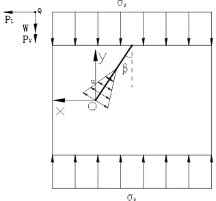
Figure 1 is a rock model of establishment. Where is center of gravity of unstable rock; u
is Fissure water pressure of control fissure; PL is horizontal seismic force per unit
length; PV is vertical seismic force per unit length; W is Gravity of rock mass per unit
length.
In Figure 1, the crack tip selects a unit. The pressure-shear stress is formed under the gravity of the rock itself. As shown in Figure 2.
In the straight line of the unit which parallel to the x axis, the included angle
be-tween the outer normal and the coordinate axes is l and m respectively. We may
know l=0, m=1, Tx=0 and Ty=0. The known parameters are brought into the boundary condition equation
u PL
W PV
Control fissure
[image:2.595.298.451.357.505.2]Q
Figure 1. The unstable rock model.
u PL
W PV
Q
[image:2.595.293.451.541.688.2]x x yx
y xy y
T l m
T l m
σ τ
τ σ
= +
= +
(1)
It will find τyx=0 and σy= −σ0. In the straight line of the unit which parallel to
the y axis, it can know σ =x 0 and τxy=0 in the same way. As we all know:
[ ]
0
0 0 0
x xy
yx y
σ τ
τ σ σ
σ = =
−
. (2) A new and old coordinate system is established in Figure 3. Where
[ ]
σ is Stress tensor of the old coordinate system;[ ]
σ′ is Stress tensor of the new coordinate sys-tem. The projection of x′ axis of the new coordinates system in the old coordinatesystem is l1 and l2 respectively; The projection of x′ axis of the new coordinates
system in the old coordinate system is l1 and l2 respectively.
It can know
[ ]
1 12 2
sin cos
cos sin
l m
l m
β β
α
β β
= =
− . (3)
[ ]
1 21 2
sin cos
cos sin
T l l
m m
β β
α
β β
= =
−
. (4)
[ ] [ ][ ][ ]
Tσ′ = α σ α . (5)
Combining formula (2), formula (3), formula (4) and formula (5) can be obtained
[ ]
0 2 02
0 0
cos cos sin cos sin sin
x x y
y y x
σ τ σ β σ β β
σ
τ ′ ′ σ σ β β σ β
′ ′ ′
′
− −
′ = =
− −
. (6)
By formula (6) can be known
(
)
2 0
0
cos
Positive and negative are direction of force cos sin
x
x y
σ σ β
τ σ β β
′
′ ′
=
−
= − . (7)
3. Deduction of Type I and Type II Stress Intensity Factor
The article assumes ZI
( )
z =∫
ZI( )
z dz and ZI( )
z =∫
ZI( )
z dz. Westergaardpro-posed the stress function [7]
u PL
W PV
u PL
W PV
Q Q
( )
( )
I I
Re Im
U= Z z +y Z z (8)
Because of ZI
( )
z =ReZI( )
z +iImZI( )
z and dz=dx i y+ d , it can be obtained( )
( )
( )
( ) (
)
( )
( )
( )
( )
I I I I
I I I I
d Re Im d d
Re d Im d Im d Re d .
Z z Z z z Z z i Z z x i y
Z z x Z z y i Z z x Z z y
= = + + = − + +
∫
∫
∫
∫
(9)( )
( )
( )
( ) (
)
( )
( )
( )
( )
I I I I
I I I I
d Re Im d d
Re d Im d Im d Re d .
Z z Z z z Z z i Z z x i y
Z z x Z z y i Z z x Z z y
= = + + = − + +
∫
∫
∫
∫
(10)
( )
( )
( )
( ) (
)
( )
( )
( )
( )
I I I I
I I I I
d Re Im d d
Re d Im d Im d Re d .
Z z Z z z Z z i Z z x i y
Z z x Z z y i Z z x Z z y
′ ′
= = + +
′ ′ ′ ′
= − + +
∫
∫
∫
∫
(11)We can carry out partial differential to Westergaard stress function
( )
( )
( )
( )
2 2
I I I I
2 2 Re Im Re Im
x
U
Z z y Z z Z z y Z z
y y
σ =∂ = ∂ + = − ′
∂ ∂ . (12)
( )
( )
( )
( )
2 2
I I I I
2 2 Re Im Re Im
y U
Z z y Z z Z z y Z z
x x
σ =∂ = ∂ + = + ′
∂ ∂ . (13)
( )
( )
( )
2 2
I I I
Re Im Re
xy
U
Z z y Z z y Z z
x y x y
τ = ∂ = ∂ + = − ′
∂ ∂ ∂ ∂ . (14)
From formula (13), formula (14) and formula (15), we can get
( )
( )
( )
( )
( )
2 I I 2 2 I I 2 2 I Re Im Re Im Re x y xy UZ z y Z z
y
U
Z z y Z z
x U
y Z z
x y σ σ τ ∂ ′ = = − ∂ ∂ = = + ′ ∂ ∂ ′ = − = − ∂ ∂ (15)
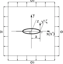
As shown in Figure 4, there is a center crack with a length of 2a in the infinite space. And its infinite distance is affected by bidirectional uniform stress σ0. Its
boundary conditions are: when y=0 and xa, it is σx=σy=0; When y=0 and x a, it is σx=σyσ0; When z→ ∞, it is σx=σy=σ0.
The stress function is obtained
( )
I 2 2 z Z z z aσ
=− . (16)
The original O point translates to the new coordinate O' point. We assume complex coordinates of any new coordinates of a bit is
ζ
.(
x a)
iy(
x iy)
a z aζ = − + = + − = − . (17)
Combining formula (16) and formula (17)
( )
(
)
(
)
(
)
(
)
I
2 2 2
a a
Z
a
a a
σ ζ σ ζ
ζ ζ ζ ζ + + = = +
x(x') y
a z
O
y'
O'
ζ
σ0
σ0
σ0
[image:5.595.308.438.74.206.2]σ0
Figure 4. Type I crack under bidirectional uniform stress.
When ξ →0, we can get
( )
(
)
0
lim
2 2
a a
F
a ζ
ζ
ζ σ
ζ σ
→
+
= =
+
Ⅰ . (19)
Because of ξ →0, formula (19) is a constant. So we can assume
( )
II 0
lim
2
K F
ζ→ ζ = π . (20) Combining formula (18), formula (19) and formula (20), we can obtain
( )
I 2 I
K = πζZ ζ . (21) We can use the same way to get
( )
II 2 II
K = πζZ ζ . (22)
4. Composite Stress Intensity Factor and Fracture Angle for
Unstable Rock
At first, we suppose that composite stress intensity factor is
I II
K=K −iK . (23)
Because the horizontal seismic force (PL) and vertical seismic force (PV) can not be
con-sidered at the same time. So we can add a coefficient C1 and C2 in front of them
respec-tively. It builds the following functions
1 1
2 2
1 2
0 or 1 0 or 1
1
C C
C C
C C
= =
= =
+ ≤
(24)
where the coordinates of the center of gravity of the unstable rock is
(
x y0, 0)
; Themaximum value of pore water pressure of control fissure is P0; Sum of forces in the
axi-al direction of y is Fy; Sum of forces in the axial direction of x is Fx. So its
infe-rence is
(
)
1 cos 2 sin
y L V
F =C P β− W+C P β. (25)
(
)
1 sin 2 cos
x L V
If D1 and D2 are constants, according to Westergaard’s stress function, we will get
( )
(
)
( )
0 0 0
I 1
II 2
2
1 3 2
1 2 5 2 2 2 y x y x
x a F y F p a x a
Z F D
a a a F a Z D a σ ζ
π ζ π ζ
π ζ τ ζ π ζ π ζ + − = + + + − + = + + (27)
Combining formula (7), formula (21), formula (22), formula (23), formula (27), we will calculate
(
0)
0I 0 2 0 II 0 sin cos
1 6 2
2 1 2
sin 2 5 2 1 2 2 2 y x y x
x a F y F a x a
K F p
a a a a K F a π π π π σ β β
πσ β
+ − = + + + − = + (28)
According to the maximum circumferential stress theory [8], we will get fracture angle
(
)
Isin 0 II 3cos 0 1 0
K θ +K θ − = . (29) We put trigonometric function into formula (29), and it will get
2 2 I I 0 II II 8 2 arctan 4
K K K
K
θ = ± + . (30)
When it is negative (“−”), fracture angle is greater than 180˚. Obviously, it is not in conformity with the actual situation. So fracture angle is
2 2 I I 0 II II 8 2 arctan 4
K K K
K
θ = − + . (31)
5. Conclusion
Considering gravity, fracture water pressure and seismic force, this paper constructs unstable rock mechanics model, which is very common in the rock engineer. What’s more, we derive composite stress intensity factor of the type I - II by fracture mechan-ics. And according to the maximum circumferential stress, we calculate theory Fracture angle by trigonometric function. In short, the results have certain theoretical guiding significance and economic value for prevention of disaster and engineering safety as-sessment.
References
[1] Nara, Y., Oe, Y., Murata, S., et al. (2015) Estimation of Long-Term Strength of Rock Based on Subcritical Crack Growth. Engineering Geology for Society and Territory, Volume 2. Springer International Publishing, 2157-2160.
[2] Zygouri, V. and Koukouvelas, I.K. (2015) Evolution of Rock Falls in the Northern Part of the Peloponnese, Greece. IOP Conference Series: Earth and Environmental Science, IOP Publishing, 26, Article ID: 012043.
http://dx.doi.org/10.4028/www.scientific.net/AMM.459.575
[4] Johari, A., Momeni, M. and Javadi, A.A. (2015) An Analytical Solution for Reliability As-sessment of Pseudo-Static Stability of Rock Slopes Using Jointly Distributed Random Va-riables Method. Iranian Journal of Science and Technology Transactions of Civil Engineer-ing, 39, 351-363.
[5] Li, Y., Zhou, H., Zhu, W., et al. (2015) Numerical Study on Crack Propagation in Brittle Jointed Rock Mass Influenced by Fracture Water Pressure. Materials, 8, 3364-3376.
http://dx.doi.org/10.3390/ma8063364
[6] Liang, L., Xiong, J. and Liu, X. (2015) Experimental Study on Crack Propagation in Shale Formations Considering Hydration and Wettability. Journal of Natural Gas Science and Engineering, 23, 492-499.http://dx.doi.org/10.1016/j.jngse.2015.02.032
[7] Westergaard, H.M.W. (1939) Bearing Pressures and Cracks. Journal of Applied Mechanics, 6, A49-A53.
[8] Erdogan, F. and Sih, G.C. (1963) On the Crack Extension in Plates under Plane Loading and Transverse Shear. Journal of Basic Engineering, 85, 519-525.
http://dx.doi.org/10.1115/1.3656897
Submit or recommend next manuscript to SCIRP and we will provide best service for you:
Accepting pre-submission inquiries through Email, Facebook, LinkedIn, Twitter, etc. A wide selection of journals (inclusive of 9 subjects, more than 200 journals)
Providing 24-hour high-quality service User-friendly online submission system Fair and swift peer-review system
Efficient typesetting and proofreading procedure
Display of the result of downloads and visits, as well as the number of cited articles Maximum dissemination of your research work