ISSN Online: 2331-4249 ISSN Print: 2331-4222
Cutting and Welding of High-Strength Steels
Using Non-Vacuum Electron Beam as a
Universal Tool for Material Processing
Thomas Hassel, Nils Murray, Georgii Klimov, Alexander Beniyash
Institute of Materials Science, Leibniz Universität Hannover, Garbsen, Germany
Abstract
Using a non-vacuum electron beam, a two-step process chain for plate materials is a feasible possibility. Cutting and welding can be performed in subsequent steps on the same machine for a highly productive process chain. The electron beam is a tool with high energy conversion efficiency, which is largely independent of the type of metal. Its high power density qualifies the non-vacuum electron beam as an outstanding energy source for the well-known NVEB welding as well as for high-speed cutting. Welding is possible with or without filler wire or shielding gas, depending on the ap-plication. The NVEB-cutting process employs a co-moving cutting head with a slid-ing seal for extremely high cuttslid-ing speeds producslid-ing high quality edges. Due to direct removal of fumes and dust, NVEBC with local suction is an exceptionally clean and fast process. The NVEB welding process is possible directly after cutting, without further edge preparation. The potential directions of development of non-vacuum electron beam technologies are discussed. An exemplary two-step process chain us-ing high-strength steel is presented to highlight possible application in industries such as general steel construction, automotive, shipbuilding, railway vehicle or crane construction. An analysis of the mechanical properties of the resulting weld seam is presented.
Keywords
Welding, High-Strength Steels, Non-Vacuum Electron Beam Welding, Non-Vacuum Electron Beam Cutting
1. Introduction
The high efficiency of energy conversion of an electron beam makes it a valuable tool
How to cite this paper: Hassel, T., Murray, N., Klimov, G. and Beniyash, A. (2016) Cutting and Welding of High-Strength Steels Using Non-Vacuum Electron Beam as a Universal Tool for Material Processing.
World Journal of Engineering and Tech-nology, 4, 598-607.
http://dx.doi.org/10.4236/wjet.2016.44056
Received: May 30, 2016 Accepted: November 19, 2016 Published: November 22, 2016
Copyright © 2016 by authors and Scientific Research Publishing Inc. This work is licensed under the Creative Commons Attribution International License (CC BY 4.0).
for any kind of thermal treatment of metal [1]. The electron beam is routinely used for welding in vacuum, in low pressure and under atmospheric conditions [2]. Other ap-plications, such as surface hardening are also conducted in atmosphere [3] or vacuum [4]. In all cases, the electron beam is inevitably generated in high vacuum. The welding process at atmospheric conditions is known as non-vacuum electron beam welding (NVEBW). Differentially pumped pressure stages act as a beam guide between the high vacuum beam generator chamber and the atmosphere [5].
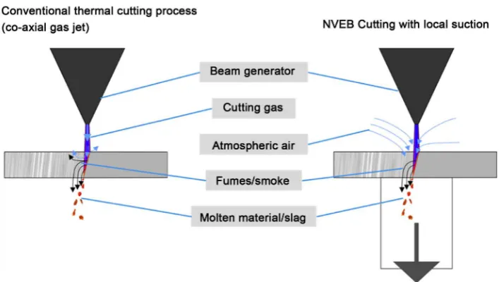
Thermal cutting with an electron beam as energy source has been shown by our group [6] [7], indicating a high potential to establish the non-vacuum electron beam for a novel cutting process. The NVEB cutting process developed at Leibniz Universität Hannover is considerably different from standard thermal melt cutting processes. In-stead of utilizing a gas jet from a nozzle above the process zone, NVEBC employs a lo-cal low vacuum from underneath. The pressure difference across the process zone from atmospheric condition at the top of the plate and low vacuum at the bottom induces a flow of gas across the melt front that removes the molten material in a highly efficient manner. Moreover, further production steps such as marking or labelling and various methods of heat treatment can be performed with such a machine due to the accurate control of beam power and power density.
This enables the use of the NVEB technology as a tool to allow cutting, welding, marking and heat treatment on the same equipment with high efficiency and produc-tivity [8]. In this publication, a two-step process chain of NVEB cutting followed by NVEB welding on the same machine is portrayed for an exemplary application for high-strength steel. The individual process steps NVEB cutting and welding are ex-plained in detail. The approach described in this publication should only be understood as an example. The shown process combination of cutting and welding with NVEB can be utilized for other materials and other industrial applications as well, such as ship-building, railway vehicle manufacturing, automotive industry, steel building or electri-cal industry for materials such as standard and high-strength steels, aluminium and copper or copper alloys.
2. General Set-Up of NVEB Equipment
Electron beams can only be generated under high-vacuum conditions due to the neces-sary protection against electrical breakdown as well as the need for low scattering rates of the electron during beam formation and focusing. Thus, most applications of elec-tron beams as a tool for material processing are performed in vacuum. On the other hand, it can be beneficial to transfer the beam from the vacuum chamber to the atmos-phere to allow processing of large parts without the need for big vacuum chambers with long pumping times.
measures are taken to improve the general performance of the vacuum creation and to prevent adverse influence of drawn in gas, particles or fumes to the beam generator. The set-up used for the study presented here is shown in Figure 1.
Electron beams under atmospheric conditions are subject to high rates of scattering due to collisions with molecules. This leads to a marked reduction of power density of the beam. Thus, the distance of the work-piece to the exit orifice, called the working distance, is a major parameter for the process. It is used to fine-tune the width of the beam and the power density available for the particular process according to its re-quirements. While cutting and marking need a rather thin, or sharp, beam acquired by using short working distances of only 1 - 6 mm, heat treatment usually employs a rather flat and wider zone of energy input at working distances of 50 - 150 mm. For welding, a working distance between 10 - 30 mm is typically used to adapt to the re-quirements of the particular joint with regard to weld width and depth. Further impor-tant parameters are the welding velocity and the beam current or beam power. The fa-cility used for this report (PTR 25 - 175 TU) uses an accelerating voltage of 175 kV with a maximum beam current of 140 mA resulting in a maximum beam power of 24.5 kW.
[image:3.595.200.549.325.674.2]3. Welding
Non-vacuum electron beam welding (NVEBW) is a well-known process in the joining industry for more than five decades. Its major fields of application are in the automo-tive industry for the fast and efficient joining of thin plates mostly from steel and alu-minium [5]. In the recent years, interest has grown to employ this technology for thicker plates made from high strength steels. This development is due to the high power density available to the process that leads to high welding speeds for higher pro-ductivity as well as lower heat input compared to standardly used arc-processes such as SAW routinely used for these purposes. We expect that lower heat input lead to a better preservation of the high strength of modern fine-grain steels with yield strengths of more than 1000 MPa utilized in industries such as crane building.
As indicated in the introduction, the major parameters for welding are beam power, working distance as well as welding speed. We were able to show, that secure, high- quality welds can be produced with NVEBW for 6 - 15 mm thick plates from materials such as D36, as well as S960QL, S1100QL and S1300QL [5] [9]. In this study 6 mm thick high-strength steels have been cut using laser cutting and then welded with NVEBW with speeds between 2.5 and 3 m/min with 100 - 130 mA beam current. In subsequent tensile tests these welds performed well with yield strengths in the range of the nominal materials values for S960QL, S1100QL and S1300QL respectively. In com-parison with plasma + MIG-welded specimens, the NVEBW weld performed similar while offering a vastly higher welding speed. With this it was shown, that NVEBW of-fers the opportunity to produce high speed and high quality weld in high-strength steels using quick and cost-effective weld preparation by thermal cutting.
4. Thermal Cutting
Non-vacuum electron beams cannot only be used for welding processes but recently our group has developed a versatile and high-speed cutting process for this tool. Most thermal cutting processes employ a concentrated gas jet directed onto the process zone to remove molten metal from the kerf. This is usually realized by a gas jet that is con-centric to an energy source; for other variations it can be either trailing, leading, or from the side. In previous work, we were able to show that such a cutting process can be realized for NVEB by adapting a trailing gas jet to existing technology [6] [7].
Adapting a gas nozzle from a standard oxy-cutter to our NVEB welder, we were able to realize a melt cutting process using nitrogen or argon as well as a NVEB-oxy-cutting process using oxygen. Space limitations due to the retrofitting of the gas jet nozzle dur-ing these preliminary works lead to a small distance between the exit orifices of the gas nozzle and the EB-machine. In addition to this, the stagnation pressure occurring from the gas flow proved detrimental to the power density of the electron beam. To establish a cutting process using the atmospheric electron beam a completely different approach proved far more useful.
beam melts the material and due to the pressure gradient between both sides of the workpiece a strong gas flow is induced across the melting front, carrying molten and evaporated metal as well as smoke away from the process zone, see Figure 2. This ap-proach avoids high stagnation pressure that would reduce the high power density of the beam and thus permits very high cutting speeds. The gas flow can interact precisely at the melt front and will force the molten metal downwards. Other than for a trailing gas jet, there is no dependence on the direction of the cut, so that curved contours can eas-ily be realized. It is important to remark that this method requires no change to the beam generator or pressure stage system of the original NVEB welder. This means that the machine can be immediately used for both processes—cutting and welding [7]. This claim will be supported further down within this publication for a chosen example from industrial practice.
[image:5.595.197.551.419.619.2]To enable free choice of cutting contour a sliding seal set-up has been developed, see
Figure 3. A pump taken from commercial vacuum clamping technology provides low
pressure at the lower side of the workpiece. A simple silicone O-ring gasket provides enough sealing that pressure regularly reach 20 - 500 mbar depending on surface qual-ity. Deflector plates and fine steel mesh filters as well as 10 m long PVC-tubing were used to protect the vacuum pump from hot metal droplets.
Several specimens of different metals and thickness were cut with this installation. Among those were stainless steel, high-strength steel, aluminium, copper and molyb-denum. Cutting speeds were higher and quality was better compared to the experi-ments with a trailing gas jet. The downward suction efficiently removes fumes and
Figure 3. Working prototype for NVEB cutting with local suction used for the examinations enabling the processing of large plates [8]. The cutting head is adjustable in z-direction to adapt for different plates thicknesses. In addition to that, it is spring mounted to compensate for un-even plate surfaces. The vacuum pump and additional filter elements are connected to the corru-gated hose. The bottom opening can be accessed to remove waste cutting material that accumu-lates in the lower arm of the cutting head. To allow larger capacity, additional reservoir elements can be fastened to the lower connector flange.
smoke, making it possible to position the beam nozzle closer to the work piece com-pared to the welding application without arcing in the generator. This allows taking advantage of the higher power density and smaller beam diameter. In addition to the effect of the aforementioned pressure gradient within the kerf both circumstances allow a faster feed rate as well as a narrower cut with little widening of the kerf and a con-ceivably smaller heat-affected zone.
5. Process Chain with One Single NVEB Machine
To assess the process chain of cutting and subsequent welding using the atmospheric electron beam, an exemplary task from industrial practice has been reproduced in la-boratory scale at IW as outlined in Figure 4. A 5.3 mm thick plate made of S1100QL steel has been cut using NVEBC with local suction to create a 420 mm diameter hole. In a subsequent step, a functional component made of 5.2 mm thick S960QL steel has been welded into the hole as a one pass butt joint using NVEBW with filler wire. These weld seams were subsequently characterized in multiple ways.
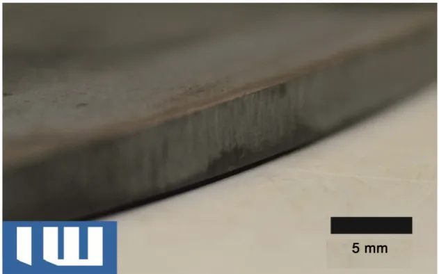
In the first step of the process chain, the NVEB cutting technique was used to make circular cut-outs for flange connections. The cutting speed was 5 m/min and the beam current was 75 mA. The process duration for the cutting-out of a hole with a diameter of 420 mm was less than 16 s. The cut edges are smooth and show only minimal droplet formation, compare Figure 5. The resulting bevel angle of the cut was 2.1˚, the cut edges can be characterized by bevel quality level 2 according to ISO 9013.
[image:6.595.194.553.72.247.2]Figure 4. Flow diagram of the exemplary process chain using NVEBC and subsequent NVEBW to insert a functional element into a flat plate of high-strength steel.
Figure 5. Bottom side of cut edge, S1100QL, 5.3 mm [8]. Only minimal excess material adheres to the bottom edge. The surface is smooth with a bevel angle of 2.1˚. This bevel angle serves as an ideal weld preparation for the NVEB welding process, enabling safe penetration of the electron beam, good outgassing characteristics and subsequently high welding speed with comparably low heat input.
tolerances present in industrial application. The specimens have then been welded at 3 m/min with 100 mA beam current. Filler wire with a feed rate of 9.5 m/min was used. Weld face and root are flat and of good quality.
Following the welding process, a heat treatment process or surface remelting could be employed to improve the properties of the weld, but these steps were not done for the particular weld presented here.
6. Weld Seam Properties
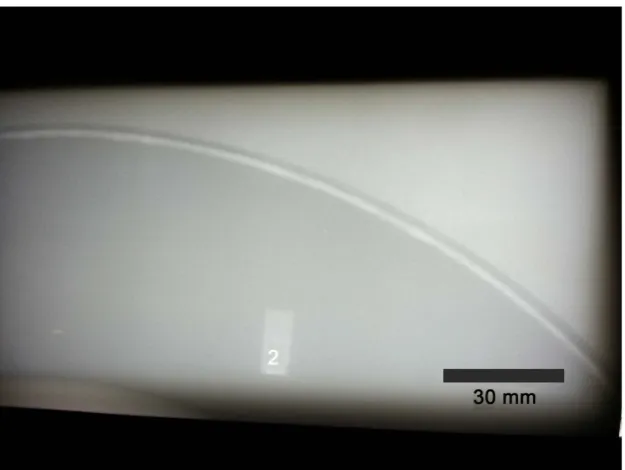
The weld seams were analysed using X-ray radiography, macro section as well as tensile and micro indentation testing. The X-ray radiographs showed no weld defects, in par-ticular no pores or cracks. A sample is given in Figure 6.
High-strength steel S1100QL, 5.2 mm thick
Inserting of pre-fabricated
part into cut-out NVEB cutting of
circular cut-out, 420 mm diameter 5 m/min, 13.1 kW
NVEB Welding 3 m/min,
[image:7.595.216.532.262.459.2]Figure 6. X-ray radiograph of a weld seam from an exemplary process chain of NVEBC and NVEBW for weld preparation and subsequent welding on one machine to produce a circular flange construction for S1100QL and S960QL. No weld defects such as pores or cracks could be identified on the radiographs indicating the high quality of the weld.
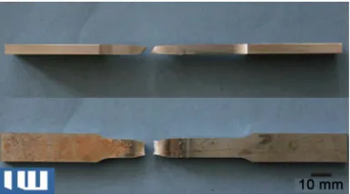
The work-piece has then been cut into several specimens for metallographic exami- nation and tensile testing. A macro section is displayed in Figure 7. The fusion zone has a width of 4.9 mm at the top of the seam and 3.0 mm at the root. The minimum width is 2.2 mm at a depth 3.8 mm beneath the top. Adjacent to the fusion zone is a re-gion of altered appearance with parallel boundaries across the whole thickness of the plate. The weld reinforcement at the root of the seam is 0.8 mm. The top of the weld seam show slight undercutting of 0.1 mm that must be avoided in future welds e.g. by increased use of filler wire.
Micro indention testing has been used to assess the progression of hardness values across the weld seam, shown in Figure 8. The weldment joins two types of high- strength steel, S1100QL and S960QL, which show distinctly different behaviour within the HAZ. The hardness within the fusion zone is 385HV1 with very little variation.
The bulk material of S960QL has a hardness of 335HV1. Within the HAZ the hard-ness drops to 290HV1. The width of the zone with reduced hardhard-ness is between 0.9 and 1.1 mm for the analysed specimens. The higher-strength S1100QL has a hardness 420HV1 in the bulk material. The hardness drops to 320HV1 in the HAZ and then rises to 442HV1 at the boundary to the fusion zone.
[image:8.595.218.531.70.305.2]Figure 7. Macro section of weld seam. The S960QL plate is on the left side, the S1100QL is on the right side of the picture.
Figure 8. Micro indention test showing Vickers HV1 values across the weld seam. The hardness drops to 290HV1 on the S960QL side from a value of 335HV1 in the bulk material. The mean hardness in the fusion zone is 385HV1. On the S1100QL side, the hardness increases up to 442HV1 at the boundary of the fusion zone, then is drops to 320HV1 in the HAZ. The S1100QL bulk material has a hardness of 420HV1.
[image:9.595.278.471.542.649.2]7. Conclusion
Non-vacuum electron beam processes offer high-power and high-power density where applicable. Both, the NVEB welding process as well as the cutting process make use of these properties leading to highly productive and economic manufacturing of steel parts relevant for crane building. NVEB-cut edges can be readily welded using the NVEB welding as was shown in an exemplary process chain for high strength steels of grade S1100QL and S960QL. Further processing steps such as pre-heating, post- heating, remelting or marking can also be performed with the atmospheric electron beam. The combination of several steps from a process chain for high-strength steel plates on one single machine allows for larger benefit from the highly efficient non- vacuum electron beam technology.
References
[1] Arata, Y. and Tomie, M. (1970) Some Fundamental Properties of Nonvacuum Electron Beam. Transactions of the Japan Welding Society, 1, 40-59.
[2] Bach, Fr.-W., Beniyash, A., Lau, K. and Konya, R. (2009) Nonvacuum Electron Beam Welding of Structural Steels. The Paton Welding Journal, 2009, 22-26.
[3] Bataev, I.A., Golkovskii, M.G., Bataev, A.A., Losinskaya, A.A., Dostovalov, R.A., Popelyukh, A.I. and Drobyaz, E.A. (2014) Surface Hardening of Steels with Carbon by Non-Vacuum Electron-Beam Processing. Surface and Coatings Technology, 242, 164-169.
https:/doi.org/10.1016/j.surfcoat.2014.01.038
[4] Zenker, R. (2009) Modern Thermal Electron Beam Processes—Research Results and Indus-trial Application. Metallurgia Italiana, 101, 1-8.
[5] Schulze, K.-R. (2012) Schweißen & Schneiden Compact Knowledge, Volume 1e—Electron beam technologies, DVS Media, Düsseldorf, 64-75.
[6] Murray, N., Beniyash, A., Konya, R., Bach, Fr.-W. and Hassel, T. (2009) Non-Vacuum Electron Beam Cutting. International Electron Beam Welding Conference, FABTECH
In-ternational and AWS Welding Show, Chicago, 17-18 November 2009, No. EBWC-006.
[7] Hassel, T., Murray, N., Konya, R., Beniyash, A. and Bach, Fr.-W. (2013) Nonvacuum Elec-tron Beam Cutting and Welding—Two Partnering Processes for Fast and Highly Efficient Metal Working. Welding in the World, 57, 315-322.
[8] Hassel, T., Murray, N. and Beniyash, A. (2015) A Process Chain Using a Non-Vacuum Electron Beam as a Universal Tool for Material Processing. Proceedings of VIII
Interna-tional Conference on Beam Technologies and Laser Application, BTLA 2015, St.
Petersburg, 20-24 September 2015, 82-90.
[9] Schwantes, S., Gerster, P. and Schulze, K.-R. (2007) Schweißen der höchstfester Feinkornstähle S1100QL und S1300QL—Ein Vergleich des Elektronenstrahlschweißen an Atmosphäre mit einem Plasma-MSG-Hybridverfahren, erschienene. In: Reisgen, U. (Hrsg.) and Willms, K. (Red.), Eds., Schweißtechnik und Fügetechnik—Schlüsseltechnologien der
Zukunft: 10. Internationales Aachener Schweißtechnik-Kolloquium, Shaker, Aachen, 543-
Submit or recommend next manuscript to SCIRP and we will provide best service for you:
Accepting pre-submission inquiries through Email, Facebook, LinkedIn, Twitter, etc. A wide selection of journals (inclusive of 9 subjects, more than 200 journals)
Providing 24-hour high-quality service User-friendly online submission system Fair and swift peer-review system
Efficient typesetting and proofreading procedure
Display of the result of downloads and visits, as well as the number of cited articles Maximum dissemination of your research work
![Figure 1. General set-up of a NVEB system with beam generation, pressure stage system and processing area [8]](https://thumb-us.123doks.com/thumbv2/123dok_us/7815703.730885/3.595.200.549.325.674/figure-general-nveb-beam-generation-pressure-stage-processing.webp)
![Figure 3. Working prototype for NVEB cutting with local suction used for the examinations enabling the processing of large plates [8]](https://thumb-us.123doks.com/thumbv2/123dok_us/7815703.730885/6.595.194.553.72.247/figure-working-prototype-cutting-suction-examinations-enabling-processing.webp)