ORIGINAL RESEARCH ARTICLE
QUADROTOR
REFERENCE
GUIDE:
MATHEMATICAL
MODEL,
REPRESENTATION
OF
INERTIA
AND
COMPUTATIONAL
APPLICATION
1
Ivan Paulo Canal and
2Manuel Martín Pérez Reimbold
1
Federal Institute of Education, Science and Technology Farroupilha, Campus Panambi,
Rua Erechim, 860 – Planalto, Panambi – RS/Brazil, 98280-000, (55)3376-8800
2Regional University of the Northwest of the State of Rio Grande do Sul, Rua do Comércio,
3000 – Universitário, Ijuí-RS/Brazil, 98700-000
ARTICLE INFO ABSTRACT
The quadrotor is the base research on situations involving movement and air transport, being technological solution for applications in industrial, academic, civil and military systems. The research area of quadrotors lacks complete and detailed information, with bibliographic material of high complexity of representation, punctual approaches, incomplete models and lack of reference information. The present research was performed with the presentation and standardization of the conventions used, followed by the structuring of the mathematical modeling, representation of the dynamics involved in the aircraft, control of the attitude of the system, representation of inertia and application of the mathematical model through implementation in computational tool. This work presents a guide for the research of quadrotors, with mathematical modeling and use of computational implementation in Matlab/Simulink, using specific aircraft characteristics, flight references, dynamics model and attitude control, obtaining output data from the model. This work represents a guide for beginners, as well as a complete reference for the application and extension of modeling and control surveys of quadrotors.
Copyright © 2018,Ivan Paulo Canal et al. This is an open access article distributed under the Creative Commons Attribution License, which permits unrestricted use, distribution, and reproduction in any medium, provided the original work is properly cited.
INTRODUCTION
Definition and Importance of Quadrotor
A quadrotor is an aircraft composed of a set of four propellers, arranged at the ends of its wings, representing an aircraft that does not need a pilot to fly, being used for recreational or work purposes, and may suffer structural variation and have more than four propellers. In informal and generalist language, the term drone is used to refer to this type of aircraft, but it will be used the most commonly used term in the scientific references "quadrotor". The quadrotor imply a promising field of research, due to their applications in fields ranging from agriculture to military use (Federal Aviation Administration, 2015; Kumar & Loianno, 2016) represented by increasing
*Corresponding author:Ivan Paulo Canal,
Federal Institute of Education, Science and Technology Farroupilha, Campus Panambi, Rua Erechim, 860 – Planalto, Panambi – RS/Brazil, 98280-000, (55)3376-8800
numbers of investments. It has gained space as a technological solution in areas of public safety, medical emergencies, disaster situations, commercial deliveries, agricultural research and management, even in the automation of procedures, mentioning only some of the most cited areas.
Qualifying Research
In spite of the importance of this field of knowledge as a technological solution, the research area of quadrotors lacks complete and detailed information, bibliographical material is difficult to understand, with high complexity of representation, punctual approaches that do not present the dynamics involved in the aircraft in an open way, incomplete models and lack of reference information. In order to qualify the research in the area, a structured guide is presented, addressing the mathematical modeling of quadrotor, their dynamics, moment of inertia and the use of computational implementation in Matlab/Simulink, as support for scientific research in the areas
ISSN: 2230-9926
International Journal of Development Research
Vol. 08, Issue, 06, pp.21018-21024, June, 2018
Article History:
Received 18th March, 2018 Received in revised form 26th April, 2018 Accepted 14th May, 2018 Published online 30th June, 2018
Available online at http://www.journalijdr.com
Key Words:
Quadrotor, Dynamic model, Transport, Inertia, Mathematical Modelling.
Citation: Ivan Paulo Canal and Manuel Martín Pérez Reimbold. 2018. “Quadrotor referenceguide: mathematical model, representation of inertia and
computational application”, International Journal of Development Research, 8, (06), 21018-21024.
of modeling and control, representing a reference guide for stakeholders in the area of knowledge.
MATERIALS AND METHODS
Conventions Used
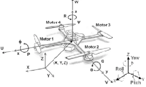
The coordinate system used for the mathematical modeling of the four-propeller multirotor, termed as a quadrotor, has two possible configurations, being "+" or "x".The "+" coordinate configuration has the X-axis along the arm of the motor 1 (which rotates counterclockwise by convention), the Y defined along the arm of the motor 2 (rotating clockwise) and the Z axis pointing up. The distance from a given motor to the axis of rotation must be the same for each. In the coordinate system for the "X" configuration, a rotation in the XY plane of 45 degrees is defined in the positive yaw direction, resulting in the position of the X axis between the motor 1 and 2. In both coordinate configurations, the axis X is assumed to be the positive direction for vehicle movement. In the Figure 1 is
[image:2.595.40.282.329.472.2]shown the quadrotor representation, conventions and coordinates.
Figure 1. Quadrotor representation, conventions and coordinates. With adaptations (D. Hartman, K. Landis, M. Mehrer, S.
Moreno, 2014)
In aerospace systems, rotation around the X axis is often called roll, rotation around the Y axis as pitch and rotation ar
Z axis as yaw. The altitude increase of the aircraft can be
agreed as a height. In Figure 1, the direction of the arrow is
positive, using the rotation based on the right hand (thumb towards the axis and other fingers indicating positive rotation about the axis).
Mathematical Modeling of Quadrotors
The most commonly used multirotor platform is the four due to its maneuverability, consisting of four individual thruster assemblies coupled to a rigid structure, as shown in Figure 1. The thrust generated by each propellant (propeller and motor assembly) jointly controlled, allows to perform the attitude control of the quadrotor. The rotors are indexed, with elements 1 and 3 rotating counterclockwise, while rotors 2 and 4 rotate clockwise. Rotating movements around the X axis (scrolling) and turning around the Y axis (arming) are performed directly through the control of the propellers that rotate in the same direction, allowing the aircraft to fly in one direction through the spin control in aro
reference. The raising motion is performed by controlling the of modeling and control, representing a reference guide for
The coordinate system used for the mathematical modeling of propeller multirotor, termed as a quadrotor, has two
The "+" coordinate axis along the arm of the motor 1 (which rotates counterclockwise by convention), the Y-axis m of the motor 2 (rotating clockwise) and the Z axis pointing up. The distance from a given motor to the axis of rotation must be the same for each. In the coordinate system for the "X" configuration, a rotation in the XY plane of the positive yaw direction, resulting in the position of the X axis between the motor 1 and 2. In both coordinate configurations, the axis X is assumed to be the positive direction for vehicle movement. In the Figure 1 is
[image:2.595.311.557.473.625.2], conventions and
Figure 1. Quadrotor representation, conventions and coordinates. (D. Hartman, K. Landis, M. Mehrer, S.
In aerospace systems, rotation around the X axis is often called roll, rotation around the Y axis as pitch and rotation around the Z axis as yaw. The altitude increase of the aircraft can be
In Figure 1, the direction of the arrow is positive, using the rotation based on the right hand (thumb towards the axis and other fingers indicating positive rotation
The most commonly used multirotor platform is the four-rotor, due to its maneuverability, consisting of four individual thruster assemblies coupled to a rigid structure, as shown in t generated by each propellant (propeller and motor assembly) jointly controlled, allows to perform the attitude control of the quadrotor. The rotors are indexed, with elements 1 and 3 rotating counterclockwise, while rotors 2 and ing movements around the X axis (scrolling) and turning around the Y axis (arming) are performed directly through the control of the propellers that rotate in the same direction, allowing the aircraft to fly in one direction through the spin control in around the axis of The raising motion is performed by controlling the
additive thrust of the four propellers. The rotational movement around the Z axis (yaw) is performed by adjusting the speed of the rotors acting in the clockwise and counterclock directions (in pairs), allowing the quadrotor to rotate around the Z axis. Considering that the system has six degrees of freedom and only four actuating elements (represented by the four propellers) the system is sub
movement of a system that has more degrees of freedom than actuators must be controlled through the modeling of the dynamic effects of the system
2012), being this modeling the base reference to describe and control the flight of the quadrotor.
Modeling the Dynamics of Quadrotor
Considering a typical implementation practitioner,
technical project reference, the practical construction of the propellant is a matter of adoption among the commercially available assemblies (Mahony
the complexity of dynamic modeling goes unnoticed, being disregarded in simplistic searches.
mathematical modeling of the dynamics that underlies the flight and control of the quadrotor is addressed. In Figure 2, the reference quantities for the modeling structure of the dynamics of a quadrotor can be visualized, where F represents the thrust force (we will standardize with the most usual terms of these quantities, in this case T), M represents the force of reaction in the opposite direction to the rotation of the propellant (standardized as Q), ω is the angular velocity of the propellant, r is the distance from the motor to the center of
mass (standardized as d). The sta
nomenclatures was adopted in order to homogenize the standards used in the research, allowing a better understanding of the published studies, due to the diversity of nomenclatures that often confuses the reader.
Figure 2. Structure of the dynamics modeling of a quadrotor. The nomenclatures a1, a2, a3 are the frame of reference, while b
are the structure of the quadrotor. With adaptations (Kumar, 2017)
The thrust of the motors is the driving force that provides the flight and maneuvers of the quadrotor, thus integrating the mathematical modeling and the control project of the system. The thrust provides a force perpendicular to the X
the body structure, in the positive Z
state thrust force (T) generated by the rotor hovering in the open air (without horizontal or vertical translation), based on the theory of the moment can be modeled as
2012):
additive thrust of the four propellers. The rotational movement around the Z axis (yaw) is performed by adjusting the speed of the rotors acting in the clockwise and counterclockwise directions (in pairs), allowing the quadrotor to rotate around the Z axis. Considering that the system has six degrees of freedom and only four actuating elements (represented by the four propellers) the system is sub-actuated. In this way, the nt of a system that has more degrees of freedom than actuators must be controlled through the modeling of the dynamic effects of the system (Mahony, Kumar, & Corke, , being this modeling the base reference to describe and control the flight of the quadrotor.
Modeling the Dynamics of Quadrotor
Considering a typical implementation practitioner, without a technical project reference, the practical construction of the propellant is a matter of adoption among the commercially (Mahony et al., 2012),thus, sometimes the complexity of dynamic modeling goes unnoticed, being disregarded in simplistic searches. In this study, the mathematical modeling of the dynamics that underlies the of the quadrotor is addressed. In Figure 2, the reference quantities for the modeling structure of the dynamics of a quadrotor can be visualized, where F represents the thrust force (we will standardize with the most usual terms is case T), M represents the force of reaction in the opposite direction to the rotation of the propellant (standardized as Q), ω is the angular velocity of the propellant, r is the distance from the motor to the center of
mass (standardized as d). The standardization of
nomenclatures was adopted in order to homogenize the standards used in the research, allowing a better understanding of the published studies, due to the diversity of nomenclatures
the dynamics modeling of a quadrotor. The are the frame of reference, while b1, b2, b3 are the structure of the quadrotor. With adaptations
(Kumar, 2017)
Ti= CT ρAri ri2ωi 2 ...(1)
Where: T is the thrust; i is the index of rotor (1,2,3,4); Ari is the area of rotor; ri is the ray of rotor i; ω is the angular velocity; ρ is the air density; CT is the thrust coefficient. In the technical literature, a simplified model of pooled parameter is used for the coefficient of thrust, representing (1) as:
Ti= CT ωi 2 ………(2)
The coefficient of thrust CT is modeled as a constant that can be determined by static thrust tests through experimental plates, thus considering the specific characteristics of the propeller set used, such as propeller radius, number of blades, angle and other features inherent in the system. With the experimental constancy of the thrust constant, one has the advantage that the drag effect will naturally be incorporated. The CT constant can also be represented in some studies as “b”(Corke, 2013). The reaction torque (Q) acting to rotate the aircraft structure around the propeller in the opposite direction of rotation is:
Qi = CQωi2 ………..(3)
Where the coefficient CQ (which depends on Ar, r, ρ) can be determined by static thrust tests, equivalent to CT. In other studies as in (Corke, 2013), CQ is presented as “k”.
It is assumed that the thrust of each rotor is oriented in the direction of the aircraft's Z axis, although this consideration is not exactly perfect since the rotor starts rotating and is transported through the air in an effect called a rotor flapping. The total thrust force provided by the propeller assembly, which has the ability to move the aircraft in the Z-axis direction, can be represented by the sum of the thrust of each propeller (represented by the index i), writing:
T=ΣTi ……….(4)
The rotation of the aircraft around the X or Y axes is performed through the thrust difference between the pairs of opposing propellers. Thus, the rotation of the aircraft around the X axis (angle ), also called rolling torque, can be represented as:
= = dT4 - dT2 ………(5)
Equation (5) can be rewritten in terms of the speed of the rotors, by substitution through equation (2):
= dCT(ω4
2 - ω2
2
) ……….(6)
In a similar way to the X axis, it is written for the rotation of the aircraft around the Y axis (angle ), also known as pitching torque:
= =dCT(ω12 - ω32) ………(7)
To represent the total reaction force around the Z axis (angle ), also called reaction torque or yaw torque, it is written:
= = Q1 + Q3 - Q2 - Q4 ………..(8)
= CQ (ω12 + ω32 - ω22 - ω42) ..………(9)
The opposite signals in equation (9) are deviating the direction of rotation of each propeller, allowing the aircraft to rotate around the Z axis with the speed control coordinated between the four propellers. The translational dynamics of the vehicle is guided by Newton's Second Law, considering the 3 reference axes of the aircraft (10). The rotational acceleration of the aircraft is given by Euler's equation of motion(Corke, 2013),where J is a 3x3 inertia matrix, which replaces the inertia of the aircraft (11). The study of inertia with application to quadrotors will be described in more detail in a specific topic, differentiating and qualifying the present research.
M ̇ =
0
0 −
0
0 ………(10)
̇ = −ω . Jω + ………(11)
Based on the integration of the previous equations, the modeling of the forces and torques that describe the dynamics of the quadrotor can be structured as:
Σ
= 0 −0 −0 0
− − ⎣⎢
⎢ ⎢ ⎡
⎦ ⎥ ⎥ ⎥ ⎤
……….(12)
In equation (12) the structure configuration of the quadrotor was considered in "+". In the case of a quadrotor frame configuration in “x”, the angular variation of 45 degrees should be considered, with the product dsin (45) being performed.
Quadrotor Attitude Control Modeling
To control the aircraft and its movements, a control structure is applied to the torques of the X, Y, Z axes. The application of a proportional and derivative controller, based on the error between the desired angle and the current one, to determine the desired torque in the aircraft. The proportional-controller (Kp) and derivative (Kd) gains can be determined by classical control design, considering the dynamics of the model and adjusting for good performance(Corke, 2013).The angular position of the aircraft relative to the X, Y, Z reference frame can be determined by an inertial navigation system. From this, we can write the control equations based on the torques:
= ( ∗− )
+ Kd( ̇∗− )
……….(13)
= ( ∗− ) + Kd( ̇∗− ) ………(14)
= ( ∗− ) + Kd( ̇∗− ) ……….(15)
Where ∗=desired angle and =current angle, with the same indexes applied consecutively. It is indicated that in some studies that ̇∗ is commonly ignored (Corke, 2013).
For the altitude control, similarly to the previous cases, it is written:
= ( ∗− )
+ Kd( ̇∗− )
+ ω0 ………(16)
Where is the required speed of the rotor to generate a thrust equivalent to the weight of the aircraft. Thus, it is recalled that the total thrust is proportional to the speed of the rotors, according to equation (2). For the equilibrium condition of the aircraft (hovering), it is necessary that the torque generated by the four propellers is equivalent to the gravity action on the mass of the aircraft, so it is possible to write:
= ………(17)
In this context, it is possible to equate the previous equations (2 and 17) by determining the speed of the rotor to generate a thrust equivalent to the weight of the vehicle:
= ………(18)
Determining the necessary speed to balance the weight of the aircraft:
= ………(19)
Euler's Representation of Position and Kinematics
The flight of an aircraft in space, can be described by positioning in three dimensions and representing its position in the middle of a sequence of maneuvers, becomes a complex task. It is possible to define a sequence of rotations around the reference axes of the aircraft, describing the rotation about the Z axis, followed by a rotation about the Y axis and followed by a rotation about the X axis, defining a sequence of rotation (Z, Y, X). Each rotation is based on a right-handed system and a single plane. Using these three rotations, a composite rotation matrix can be created, which can transform the movement of the body structure of the aircraft (b) to the inertial reference system (i). The resulting rotation matrix can be found using the multiplication of matrices, according to equation (20), using the principles of Euler kinematics. In equation (20) the abbreviations (s, c) represent the sine and cosine functions, respectively.
u =
1 0 0
0 c(ϕ) s(ϕ)
0 −s(ϕ) c(ϕ)
c(θ) 0 −s(θ)
0 1 0
s(θ) 0 c(θ)
c(ψ) s(ψ) 0
−s(ψ) c(ψ) 0
0 0 1
u ……(20)
By performing the multiplication of matrices of equation (20) as a function of the angles of yaw, pitch and roll, the aerospace rotation matrix with sequence (Z, Y, X) is obtained from an inertial reference frame for the aircraft. The rotation matrix is important for the resolution of the velocity and position equations. Using sequential rotation matrices, the angular velocity of the aircraft in its structure is related to the changes in angular rotation, thus making it possible to represent the state of the aircraft in flight in relation in relation to an inertial reference system.
Moment of Inertia
In order to qualify the project of quadrotors, with a broad approach of the involved variables (often disregarded), this study is presented contemplating the mathematical modeling of the moment of inertia. The moment of inertia relates the
added rotational movement of translational motion,
determining how the rotational velocity is affected by the
application of torque. In the same direction this approach of quadrotors is conducted, with the range of the rotational movement of the propellers and the translational movement of the aircraft. For the rotational movement, it can be written that the sum of the applied forces (F) is related to mass (m) and linear acceleration (a), according to equation (21), while for the translational movement, the sum of the torques ( ) is related to the moment of inertia (J) and the angular acceleration ( ̇), corresponding to equation (22).
∑ = ………(21)
∑ = ̇ ………(22)
For the design and study of objects with translational movement, as in the case of flight of quadrotor aircraft, it is of fundamental importance to determine the moment of inertia, providing control of the resulting torque in the aircraft reference axes, which results in flight and maneuverability of the same. The moment of inertia modeling depends on the mass of the object under analysis, in addition to how the mass is distributed around the axis of rotation. For objects with structure composed through multiple moments of inertia, represented by multiple geometries, it is necessary to determine the resulting inertial momentum matrix (J) in the reference axes X, Y and Z, that in the case of a system quadrotor is presented in equation (23). The inertial matrix describes the moment of inertia of the quadrotor in its respective axes, being directly related to the flight of the system.
=
0 0
0 0
0 0
………(23)
In order to determine the inertia of the quadrotor system, it is assumed that there is a symmetry of the perfect structure around the X, Y and Z axes, in addition to considering a center of mass corresponding to the geometric center that joins the arms of the aircraft, forming thus a matrix of diagonal inertia. The formation of the diagonal matrix is related to the positions of X and Y of the quadrotor's arms (reference b) in relation to the inertial reference system (reference a), being conserved in both configurations of arms, the "+" and "X"(D. Hartman, K. Landis, M. Mehrer, S. Moreno, 2014). In order to structure the mathematical modeling of the inertia of the quadrotor, the following procedure will be carried out and the following considerations will be made:
The quadrotor is divided into fractional components
according to their geometry (motors, speed
controllers, central hub of the structure and support arms of the propellers), modeling each component as simplified geometric forms, with constant density;
The weight and spatial dimensions of each
component are verified;
With the aid of the Parallel-Axis Theorem, the contribution of the moment of inertia of each component of the quadrotor is determined, observing the reference axes of the vehicle. In this step, each quadrotor component will result in a moment of inertia referenced to the X, Y and Z axes.
singular component in their respective axes
(∑ , ∑ , ∑ ).
The Parallel Axis Theorem provides the moment of inertia through the center of masse of the component and the perpendicular distance between two parallel axes, allowing to model the inertia of the component in relation to the inertial referential of the vehicle. Thus, the inertia of each component of the aircraft in the reference axes (Jx, Jy, Jz) is determined and subsequently the inertia moment resulting from the system is determined by applying of studies the(D. Hartman, K. Landis, M. Mehrer, S. Moreno, 2014). The equation of the Parallel Axis Theorem can be written as:
= + ……….(24)
In equation (24) JCOM is the inertia of each fractional component of the aircraft in relation to a reference axis, being parallel to the axis that we wish to reference the inertia. In the same equation, "m" is the mass of the component and "d" is the perpendicular distance between the parallel axes (reference axis of the aircraft for which the inertia and axis where the component is positioned). It is observed that the orientation of the distance "d" can be disregarded, due to the quadratic elevation of the equation.
Motors Inertia
To determine the inertia of the motors (JM), their geometries will be simplified as solid cylinders, which will result in moments of inertia JxM, JyM and JzM, in their respective axes. The determination of the moment of inertia depends on the mass of the motor (m), the distance from the engine component to the reference center of the aircraft (dm), the height of the motor above the aircraft lift arms (h) and the radius of the motor (r). Two equations will be needed: from a cylinder rotating around its axis, equation (25) for the reference axes X and Y; and a cylinder rotating about its central axis, equation (26) with reference to the Z axis.
= + ℎ ………(25)
= ………(26)
The moment of inertia of the motors in the X and Y axis is the same, due to the symmetry of the system, writing equation (27):
, = , = 2 + ℎ + 2 + ℎ +
………..(27)
For example, to determine Jx,M the first term in brackets in equation (27) represents the motors 1 and 3 that revolve around a diameter coincident with the X axis of the aircraft, in this case the distance from the term mdm2 is zero, being omitted (parallel axis theorem). The second term in brackets represents motors 2 and 4, which has a rotational diameter parallel to the X axis of the aircraft, in this case there is the distance in the term mdm2, the distance perpendicular between the axis of rotation of the motor and the reference axis of the aircraft.
To determine inertia in the Z-axis (Jz,M), equation (26) is used which represents a cylinder rotating about its central axis. The four motors are rotating about the central axis, so that the axis of rotation of the motors is parallel to the Z axis, making valid the use of the term mdm2, where the distance "d" is the perpendicular distance between the axis of rotation of the motors and the Z axis. In this way, the inertia of the motors in the Z axis can be written as (28).
, = 4 + ...(28)
ESC’sInertia
In order to determine the inertia of the electronic speed controllers ESC's (JS), analogous to that used in calculating the motors, their geometries will be simplified as flat plates, which will result in the moments of inertia JxS, JyS e JzS. The mass of an ESC is represented by (m), the distance from the ESC component to the reference center of the aircraft by (ds), the width of the ESC by (a) and the length of the ESC by (b). The equations of a flat plate rotating around the X, Y and Z axes, representing the ESC, can be written as:
, = ……….(29)
, = ………(30)
, = ( + ) ……….(31)
For the determination of the inertia of the ESC’s in the reference frame X, the components ESC’s 1 and 3 (with notation corresponding to the respective motors) are analyzed with axis of rotation coincident with the axis X of the aircraft, thus the term mds2, is null by the parallel axis theorem. By analyzing the ESC’s components 2 and 4, with axis of rotation parallel to the X axis of the aircraft, the use of the term mds2 is valid. Due to the symmetry of the vehicle on the X and Y axes, the inertial components Jx,S and Jy,S of the ESC's can be written as in (32):
, = , = 2 + 2 + ………….(32)
In order to determine inertia in the Z axis (Jz,S), the four ESC’s are rotating about an axis parallel to the Z axis of the aircraft and thus, in the term mds2, the distance represents the displacement from the ESC to the Z axis of the aircraft. Thus, one can write (33) to represent the inertia Jz,S.
, = 4 ( + ) + …………..(33)
Central Hub Inertia: The four propellers of the quadrotor are each supported by their respective arms, these arms being connected a central hub, thus defining a moment of inertia of the central hub (JH). The central hub provides physical support for propeller arms and support for onboard electronics, its geometry being simplified by a solid cylinder with moments of inertia Jx,H, Jy,H, Jz,H. In the central hub representation of the structure, its mass is defined as (m), the radius of the central union by (r) and the height of the central union by (H). The inertia of the central hub component can be determined by
equation (34) for the X and Y axes, in addition to equation (35) for the Z axis. The determination of the inertia , is
performed considering the rotation around a central diameter coincident with the X axis of the aircraft, then the distance component relative to the Parallel Axis Theorem is zero, being null. Because of the symmetry of the aircraft, , has the same
representation of , , resulting in equation (34).
, = , = + ………...(34)
The determination of inertia in the Z axis is performed by the representation of a cylinder rotating about the central axis, which coincides with the Z axis of the aircraft, indicating that the distance component of the Parallel Axis Theorem is zero. In this way, the inertia component of this axis is represented by equation (35).
, = ……….(35)
Arms Inertia
For the determination of the inertia of the propellers' arms ( ), their geometries will be simplified by solid cylinders, defined in the reference axes as , , , e , . The propeller support
arms are described as a function of the total length of one of the arms, represented by (L), the radius of the cylinder representing the arm (r) and the mass of one of the arms (m). The equation of the inertia of the arms in the X and Y reference frames is shown in (36), while the inertia of the Z component is dependent on (37).
= ...………(36)
= + ………..(37)
For the determination of the inertia in the X-axis ( , ), the
representative cylinder is rotating about a central axis and also around its diameter, resulting in the combination presented in equation (38).
, = , = 2 + 2 + + …...(38)
The first term in the brackets of equation (38) is representative for the arms 1 and 3, which are rotating about a central axis, coincident with the X axis of the aircraft. Thus, the distance term observed for the Parallel Axis Theorem is zero. The second bracket in the equation is for the arms 2 and 4, which are rotated around a diameter located from a distance “da”
from the X axis of the aircraft. Thus, the Parallel Axis Theorem is represented by the term . It is observed that due to the symmetry of the aircraft, the inertia in X and Y must be the same. The inertia of the arms in the reference frame Z ( , ), is given in equation (39). It is considered a cylinder
rotating around the diameter, located at a distance “ ” from the Z axis of the aircraft and thus, in the parallel axis theorem,
the terminology is valid.
, = 4 + + ……….(39)
Because the aircraft is symmetrical and consists of four arms, the product four times is justified by the representation of each arm.
Quadrotor Resultant Inertia
The Parallel Axes Theorem, allowing the modeling of the moment of inertia of each quadrotor component in relation to the referential inertial of the vehicle. Thus, it is determinate the inertia of each component of the aircraft (motor, ESC, central hub and arms) in the reference axes and is the moment of inertia resulting from the system. In this way, the moment of inertia of the quadrotor can be represented in its respective axes as:
= ∑ = , + , + , + , ……….(40)
= ∑ = , + , + , + , ……….(41)
= ∑ = , + , + , + , ………(42)
Once the inertial values have been determined by reference axes, the quadrotor can be written as inertial matrix, as previously described in equation (23). With the inertia matrix, it is possible to carry out simulations of the state of the quadrotor and its relation with the moment of inertia. For this, we used the equations (21) and (22) that were added to the mathematical model of the quadrotor, implemented in Matlab/Simulink with the robotic toolbox developed by(Corke, 2013).
RESULTS
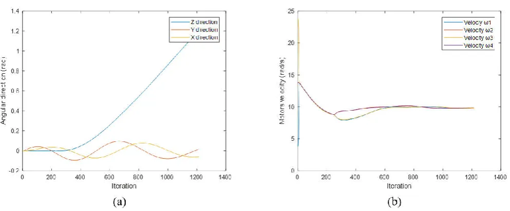
With the model open, it is possible to carry out the input configurations and check the desired outputs. A data output file is created during the execution of the model allowing the ex-trapping of output data corresponding to an initial parameterization. The output data is available in the "result" file, which can be accessed in the Matlab command window. This data available in the output file represents position, orientation, velocity, and orientation rate. The output matrix of the system consists of 16 columns, which can be verified by the "about (result)" command, structured in the form of a row by time step, where each row contains a state vector, where the elements 1-12 represent (x, y, z, yaw, pitch, roll, dx, dy, dz, dyaw, dpitch, droll), while rotor speeds are represented by elements 13-16 (ω1, ω2, ω3, ω4), respectively. The quantities are represented according to the units of the International System (SI).For the configuration of inputs and inertia performed, it is possible to verify some of the results that can be obtained through the model, which are presented in Figures 3. The results make it possible to verify the behavior of the quadrotor as a function of a predefined input, demonstrating that the model used has stability and represents the dynamics of the system.
DISCUSSION
The mathematical modeling of the dynamics of the system is fundamental for the design of quadrotors, being an indispensable item for the scientific research in the area, representing the gateway for new researchers, as well as the reference for the improvement and qualification of the researches. The understanding of the magnitudes involved, their action and interaction allow to define the maneuverability of the aircraft, as well as to design this capacity. The control of the quadrotor in one direction can only be done by isolating the mathematical model of torques in the reference axes, but for maneuverability it must be considered in conjunction with the axes, besides the resulting summation thrust. The complexity of the dynamics involved in the system demonstrates that mathematical modeling is a good solution for the design of quadrotors.
The structured organization of the mathematical model of the quadrotor leads to an understanding of the dynamics involved in the system, as well as to demonstrate the degree of maturity of the research. The control strategies are significant fields of investigation, which can be subsidized through the presented implementation, as well as investigations of aircraft with the alteration of characteristics, verification of limitations and possible solutions, as well as the promotion of new structures research.
Acknowledgments
To Federal Institute of Education, Science and Technology Farroupilha, through the institutional program to encourage teacher qualification (PIIQP).
REFERENCES
Corke, P. 2013. Robotics , Vision and control fundamental
(Springer T). India.
Corke, P. 2018. Robotics Toolbox. Retrieved April 22, 2018, from http://petercorke.com/wordpress/toolboxes/robotics-toolbox
D. Hartman, K. Landis, M. Mehrer, S. Moreno, J. K. (2014). Modeling and simulation of quadcopter vehicles.
Retrieved October 24, 2017, from
https://github.com/dch33
Federal Aviation Administration. 2015. Aviation Data e
Statistics. Retrieved August 6, 2015, from
https://www.faa.gov/
Kumar, V. 2017. Robotics: Aerial Robotics. Retrieved
February 6, 2017, from https://pt.coursera.org/
specializations/robotics
Kumar, V., & Loianno, G. 2016. ICRA 2016 TUTORIAL:
AERIAL ROBOTICS. IEEE International Conference on
Robotics and Automation.
Mahony, R., Kumar, V., & Corke, P. 2012. Multirotor aerial vehicles: Modeling, estimation, and control of quadrotor.
Robotics Automation Magazine, IEEE, 19, 20–32.
Figure 3. (a) Angular orientation of the quadrotor in the axes X, Y, Z. (b)Motors velocity of quadrotor