Design and Implementation of Fuzzy Logic Controller for
Intelligent Gantry Crane System
Wahyudi1 and J. Jalani2
1
Department of Mechatronics Engineering, Faculty of Engineering
International Islamic University Malaysia, Jalan Gombak, 53100 Kuala Lumpur, Malaysia 2
Department of Mechatronics and Robotic
Kolej Universiti Teknologi Tun Hussein Onn, 86400 Parit Raja, Batu Pahat, Johor, Malaysia 1
[email protected], [email protected]
ABSTRACT
Gantry crane is a machine that moves payload from one point to another point. Recently, most of gantry cranes use open loop system to control position while anti-swing control is done manually by skilful operators. Therefore, skilful operators are needed to be trained in order to operate the gantry crane efficiently and safely. The performance of the gantry cranes are heavily depends on their experiences and capability. This may not be practical to control the gantry crane because human skills are restricted by fatigue problem and will affect the performance of the gantry crane. In addition, it is well known that open loop system is sensitive to the parameter variations and disturbances. To overcome the above-mentioned problems, feedback control is adopted in this paper. Fuzzy logic controllers are proposed for gantry crane system. Fuzzy logic control is designed based on information of the skilful operators. The effectiveness of the proposed controller is evaluated experimentally using a lab-scale gantry crane. The experimental result shows that fuzzy logic controllers have produced good result for anti-swing controller.
1. INTRODUCTION
Gantry cranes are widely used in industry for transporting heavy loads and hazardous materials in shipyards, factories, nuclear installations, and high building construction. The crane should move the load as fast as possible without causing any excessive movement at the final position. However, most of the common gantry crane results in a swing motion when payload is suddenly stopped after a fast motion [1]. The swing motion can be reduced but will be time consuming i.e. reduce facility as well as productivity Moreover, the gantry crane needs a skilful operator to control manually based on his or her experiences to stop the swing immediately at the right position. Furthermore to unload, the operator has to wait the load stop from swinging. The failure of controlling crane also might cause accident and may harm people and surrounding.
The swing motion can be reduced and stopped without using the controller. However, it will be time consuming and eventually reduce the facility and productivity of the gantry crane system. Even though the skillful operators operate the crane, they will still face some constraints such as fatigue problem. This phenomenon can cause inconsistent performance of the gantry crane systems and might cause accident. Various attempts to control gantry cranes system based on open loop system were proposed. For example, open loop time optimal strategies were applied to the crane by many researchers [2-4]. They came out with poor results because open loop strategy is sensitive to the system parameters (e.g. rope length) and could not compensate for wind disturbances. Another important open loop strategy is the input shaping introduced by Karnopp [5], Teo [6] and Singhose [7]. Even though they claimed that input shaping is good in controlling the open loop system but it still faces sensitiveness to the external disturbances and parameter variations.
experimental result showed that the intelligent gantry crane system had produced good performances compared with the crane system controlled by classical PID controllers.
2. PROPOSED CONTROL STRUCTURE
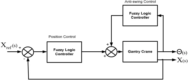
The structure of the proposed controller for the gantry crane system is shown in Fig. 1. The proposed controller consists of fuzzy logic controllers for both position and anti-swing control respectively. The objective of the proposed fuzzy logic controllers is to control the payload position X(s) so that it moves to the desired position Xref(s) as fast as possible without excessive swing angle of the payload Θ(s). The design of fuzzy logic control is based on expert knowledge. For example the expert knowledge of skillful operator during the manipulation of gantry crane system is adopted in fuzzy logic controller design. It shows that fuzzy logic controller is a technique that can realize the skill of human operators and the design rules describe the subjective fuzziness of operators’ experiences instead of the use of control theory based on mathematical model of the plant.
) s (
X
) s (
ref
X
) s (
[image:2.612.147.478.242.384.2]Θ
Fig. 1. Proposed fuzzy-based automatic gantry crane system
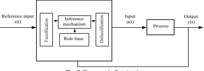
Fuzzy logic controller is one of the recent developing methods in control that earned its popularities. The idea behind the fuzzy logic controller is to write the rules that operating the controller in heuristic manner, mainly in If A Then B format. In general, as shown in Fig. 2, fuzzy logic controller is constructed by the following elements [8]:
• A rule base (a set of If-Then rules), which contains a fuzzy logic quantification of the expert’s linguistic description of how to achieve good control.
• An inference mechanism (also called an “inference engine” or “fuzzy inference” module), which emulates the expert’s decision making in interpreting and applying knowledge about how best to control the plant.
• A fuzzification interface, which converts controller input into information that the inference mechanism can easily being used to activate and apply rules.
• A defuzzification interface, which converts the conclusions of the inference mechanism into actual inputs for the process.
Fig. 2. Fuzzy controller structure
3. DESIGN OF FUZZY LOGIC CONTROLLERS
The main features of the fuzzy logic design process consist of the development of input and output of the membership functions. In the case of gantry crane, error and error rate of position and swing angle are taken into consideration as an input. Meanwhile, the voltage is taken as an output. Since there is no specific form to be used when designing fuzzy logic control [8], thus, the basic triangle and trapezoidal forms are chosen for input and output membership functions. In most cases, the performance of fuzzy control is minimally influenced by the shapes of memberships, but mainly by the characteristics of control rules [9].
3.1 Membership Functions
The membership functions for error, error rate and voltage of the position control consist of Negative (N), Zero (Z) and Positive (P) as shown in Figs. 3 and 4 respectively. The universe of discourse is from -100 to 100 cm for error, -12.85 to 12.85 cm/s for error rate and -1.4 to1.4 for voltage. Meanwhile, membership functions for error, error rate and voltage of anti-swing control consist of Negative Big (NB), Negative Small (NS), Zero (Z), Positive Small (PS) and Positive Big (PB) as shown in Figure 4.6, 4.7 and 4.8 respectively. The universes of discourses of error, error rate and input voltage are from -1 to 1 rad, -2.5 to 2.5 cm/s and -1.4 to1.4 V respectively.
-100 -75 -50 -25 0 25 50 75 100 0.0
0.5 1.0
-12 -8 -4 0 4 8 12
0.0 0.5 1.0
-1.5 -1.0 -0.5 0.0 0.5 1.0 1.5 0.0
0.5 1.0
P Z
(a) Input membership function of error e
D e gre e of m e m be rs hi p µe Error cm N . . P Z
(b) Input membership function of error rate
D e gre e of m em be rs hi p µe
Error rate cm/s N
P Z
(a) Output membership function
D e gre e of m e m be rs hi p µu Voltage Volt N
-1.0 -0.5 0.0 0.5 1.0 0.0
0.5 1.0
-2.50 -1.25 0.00 1.25 2.50 0.0
0.5 1.0
-1.5 -1.0 -0.5 0.0 0.5 1.0 1.5 0.0
0.5 1.0
PS
NS Z PB
(a) Swing angle membership function
De
gre
e of m
e m b e rs h ip µθ
Swing Angle rad NB PS NB . . PB Z
(b) Swing angle rate membership function
De
gre
e of m
e m b e rs h ip µθ
Swing Angle Rate rad/s NS
PS
NS Z PB
(a) Output membership function
D
e
gre
e of m
em be rs hip µu Voltage Volt NB
3.2 Fuzzy Rule Base
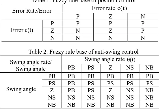
[image:4.612.168.445.149.338.2]The rules of fuzzy position and fuzzy anti-swing controls are adopted from operator’s knowledge and experiences. Basically, the operator considers the target position, actual position and the crane speed during operation. Therefore, error and error rate are used in order to generate the rules. Tables 1 and 2 list the generated linguistic rules for position and anti-swing control respectively.
Table 1. Fuzzy rule base of position control Error rate e(t)
Error Rate/Error
P Z N
P P P P
Z N Z P
Error e(t)
N N N N
Table 2. Fuzzy rule base of anti-swing control Swing angle rate θ(t)
Swing angle rate/
Swing angle PB PS Z NS NB PB PB PB PB PB PB PS PB PS PS PS PS Z PB PS Z NS NB NS NS NS NS NS NB Swing angle
NB NB NB NB NB NB
3.3 Fuzzy Inference and Defuzzification
The fuzzy inference for position control has adopted the Mamdani’s Min-Max method which the fuzzy control output µv for the input µeand µeis computed as
[
e e]
u =∨µ ∧µµ (1) where∨and∧denote the maximum and minimum operators respectively while µu, µe and µvdenote degree of memberships of the error, error rate and voltage control action respectively. Meanwhile, for the anti-swing control, the same technique is used for fuzzy inference. The Mamdani’s Min-Max method which the fuzzy control output µv for the input µθand µθis computed as
[
µθ∧µθ]
∨ =
µu 2)
where µu, µθ and µθdenote degree of memberships of the error, error rate and voltage control action respectively.
Furthermore, in order to convert the fuzzy value to the crisp value of fuzzy position and anti-swing control, the centre of area of defuzzification method is used.
∫
∫
µ µ =
u u u
u o
du ) u (
udu ) u (
u (3)
where uo is control input voltage obtained using Centre of Area (COA) defuzzification method.
4. IMPLEMENTATION AND RESULTS
4.1 Experimental Setup
xPC Target. The RTW environment provides a real-time operation using personal computers and multifunction I/O boards. However, the use of RTW still requires the development of custom interface programs for correct communication with multifunction I/O boards. In order to overcome this problem, xPC Target is included in the software configuration. The xPC Target software supports and provides built-in drivers for many industry standard DAQ card including the PCI-6024E DAQ card by National Instrument which is used in the prototype of the automatic gantry crane system. A personal computer is used as a Host Computer. Windows operating system and other required software are running in the Host Computer. The propsed controllers are developed in Simulink using its blocks and Fuzzy Logic Toolbox, and then it is built so that C code is generated, compiled and finally a real-time executable code is generated and downloaded to the Target Computer.
Fig. 5. Lab-scale intelligent gantry crane system
4.2 System Performances
[image:5.612.88.524.549.713.2]The performances of the proposed fuzzy logic controllers were compared experimentally with the PID and PD controllers which are designed and discussed in [10]. Figures 6 and 7 show the responses of gantry crane controlled by the proposed controllers as well as the classical PID controllers when the 40 cm and 70 cm step input references were used. The detailed performance comparisons are shown in Table 3 for position control and Table 4 for anti-swing control. Here, the performances of position control system were evaluated based on overshoot, settling time, rise time and steady state error. On the other hand, anti-swing control was based on maximum swing amplitude and settling time.
Table 3. Positioning performances
Controller Reference (cm)
Overshoot (%)
Settling time (s)
Rise Time (s)
Steady-State Error (cm)
40 5.33 50 2.92 -0.803
PID/PD
70 7.92 50 4.59 -2.19
40 2.62 5.44 3.00 0.465
Fuzzy/Fuzzy
70 1.71 6.73 4.96 0.158
Table 4. Anti- swing performances
Controller Reference (cm) Maximum Amplitude (rad Settling time (s)
40 0.04 10.9 PID/PD
70 0.04 12.7 40 0.06 5.4 Fuzzy/Fuzzy
The results show that the fuzzy logic controller for position control gave smaller overshoot, shorter settling time, shorter rise time and smaller steady-state error than the PID controller. Therefore it can be concluded that, the proposed fuzzy position control system is better than the classical PID controller. Moreover, as shown in Fig. 6(b) and 7(b), the fuzzy logic controller for anti-swing control gave faster settling time than the PD controller. Although the maximum swing amplitude due to the fuzzy logic controller was slightly higher then due to PD controller, it was acceptable. In general, the results confirmed that the fuzzy logic controllers were successfully controlled the swing angle better than the PD controller and performed inconsistent results at different desired positions. As the proposed fuzzy logic controllers give a better performance than the classical PID controller for both position and anti-swing controllers, it can be concluded that the proposed fuzzy-based intelligent gantry crane system is better than classical gantry crane system.
0 10 20 30 40 50
0 10 20 30 40 50
0 10 20 30 40 50
-0.06 -0.04 -0.02 0.00 0.02 0.04
PID FLC
(a) Position response
P
o
si
tion
c
m
Time s
PID FLC
(b) Swing angle response
Swi
n
g an
gl
e r
a
d
Time s
0 10 20 30 40 50
0 20 40 60 80
0 10 20 30 40 50
-0.06 -0.04 -0.02 0.00 0.02 0.04
PID FLC
(a) Position response
P
osit
ion cm
Time s
PID FLC
(b) Swing angle response
S
w
in
g ang
le
rad
Time s
Fig, 6. Responses to a 40 cm step input Fig. 7. Responses to a 70 cm step input
5. CONCLUSIONS
The intelligent gantry crane system has been developed by adopting fuzzy logic controllers. The proposed intelligent gantry crane system contains two fuzzy logic controllers for controlling the both position and anti-swing motion of the payload. The both fuzzy logic controllers were designed based on the crane operator experiences. The performance of the proposed intelligent gantry crane system was evaluated experimentally using a lab-scale gantry crane. The result showed that the proposed system had better performances compared with the classical crane system.
REFERENCES
[1] H.M. Omar, Control of Gantry and Tower Cranes, M.S. Thesis, Virginia Tech., Blacksburg, VA, 2003.
[2] Y. Sakawa and Y. Shindo, “Optimal Control of Container Crane”, in Proc. The 8th Triennial World Congress of IFAC, Kyoto Japan, pp 463-468, August 1981.
[3] G.A. Manson, “Time-Optimal Control of and Overhead Crane Model”, Optimal Control Applications & Methods, Vol.3, No. 2, pp. 115-120, 1992.
[5] B.H. Karnopp, F.E. Fisher and B.O. Yoon, “A strategy for moving mass from one point to another”, Journal of the Franklin Institute, No. 329, pp. 881-892, 1992.
[6] C.L. Teo, C.J. Ong and M. Xu, “Pulse input sequences for residual vibration reduction”, Journal of Sound and Vibration, Vol. 211, No. 2, 157-177, 1998.
[7] W.E. Singhose, L.J. Porter and W. Seering, “Input shaped of a planar gantry crane with hoisting”, in Proc. American Control Conference, Albuquerque, NM, pp. 97-100, 1997.
[8] K.M. Passino and S. Yurkovich, Fuzzy Control, Addison Wesley Longman, 1998.
[9] H.H. Lee and S.K. Cho, “A New Fuzzy Logic Anti_Swing Control for Industrial Dimensional Overhead Cranes”, Thesis, Department of Mechanical Engineering, University of Suwon.