Journal of Chemical and Pharmaceutical Research, 2013, 5(12):1-7
Research Article
CODEN(USA) : JCPRC5
ISSN : 0975-7384
Human arms discus throw model based on image reconstruction
Hua Fu
Institute of Physical Education, Changchun Normal University, Changchun, China
_____________________________________________________________________________________________ABSTRACT
Video images analysis and computer vision theory have been widely used in the reconstruction and projection of human motion, tracking athletes ’motion and trajectory from sports video, getting human motion model and calculating motion parameters, make it easy for physical educators to research athletes’ motion flaws, improve training level for the athlete’s in a scientific way, and achieve upgrading more quickly and effectively. In this paper, discus throw was taken as a research object, arm motion trajectory and detailed force status during its rotating process were studied and got the results that maximum throwing distance would be obtained in the way of reducing proactive force of arms and trying to achieve the maximum discus horizontal velocity. In the paper, video projection and computer vision theory were applied to reconstruction simulation on the main joint of arms, then connect into a line, finally form the 2D image till fully achieve arms motion model reconstruction .
Key words: computer vision, video tracking, projection, arms motion model
_____________________________________________________________________________________________
INTRODUCTION
Video image analysis for all kinds of sports as a hot topic in computer vision research has been widely used in the area of measurement and analysis of athlete’s training, which plays decisive roles in modern competitive sports. By researching 3D human movements and building reconstruction motion model, training level in sports can be improved , scientific and technological content in sports be enhanced. Fully combining sports and modern science to increase such science and technological content is a timeless topic in human society[1]. However, applying computer vision theory to reconstruct sports was a really tough thing, its researching work couldn’t be moved forward easily, therefore many scholars and seniors made some tentative studying in all aspects.
The discus is a sport that athletes take up correct hold posture and ready position, rapidly complete pre-swing and rotation movements, enable discus achieve the maximum speed and best angle so that fulfil its maximum throwing range. Arms rotation plays decisive role in reaching a peak performance of this sports. As one of the oldest competitive sports, discus have experienced several centuries’ baptism, the records are constantly being refreshed, while so far the results have been more and more difficult to break.
In general, the human body can be presented in image in the form of its contour, edge, motion, and color so on. Therefore, on the basis of previous studies, this paper using computer vision and video observation projection technology to reconstruct arms motion in discus, more vividly describing arms force bearing and all kinds of parameters during rotation, more clearly showing the arms motion trajectory[2]. It provides an effective, convenient and feasible method on training and analyzing of discus motion for future sports researchers.
2. Technical features analysis for Discus throws Basic Movements
2.1. Technical analysis for Discus throws Basic Movements
[image:2.595.132.482.119.173.2]As shown in Figure 1, discus throw is a very complicated process, which includes about five aspects as grip, preliminary pose, pre-swing, rotation and last exertion so on.
Figure 1 Discus throw techniques figures
[image:2.595.216.399.220.495.2]Grip and preliminary pose as shown respectively in figure 2 and figure 3, requires five fingers nature separate ,wrists slight bent, back to the throwing direction, two feet apart , and stand inside circle.
Figure 2 Discus grip method
Figure 3 Preliminary pose
Pre-swing, rotation and the last exertion is a fast and highly explosive process, basically done at one goes without interruption. After discus leaving the hand, affected by whole strength focus on the throwing arm, body is hard to keep balance so that legs should be switched, body is turned left and low to maintain balance and complete discus throwing movements.
2.2 Analysis for arms movement trajectory and force in discus throw
The discus throw requires might as well to achieve a maximum horizontal velocity and most suitable throwing angle in rotation and last exertion stage[3]. Arms motion, strength and angle would have a direct effect on discus throwing’s horizontal velocity, so it’s essential to make research on arms motion trajectory and analysis for arms force.
Discus horizontal velocity should be large enough if maximum throwing range wanted to be achieved, so it’s very strict with arms force distribution and movement requires. Arms force in vertical direction should be reduced as much as possible, while in horizontal direction be increased, making discus horizontal velocity constantly increased to the maximum level.
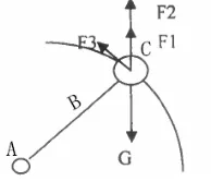
[image:2.595.256.353.665.748.2]Figure 4 shows the force analysis in rotation—A represents shoulder as the arm rotations axis location; B is arms, C is discus. In rotation, discus movement’s trajectory roughly a circular motion of radius arms centered at shoulder axis. G is discus gravity, F1is discus upward force given by arms; F2 is discus upward traction given by arms
moving in the rotation direction while in rotation process; F3 is discus force moving along the discus given by
arms, namely force in crossing center of movements trajectory.F1 Mainly is active force generated by muscle
contraction, while F2and F3 are tension generated by muscle due to its stretch during rotation.F2andF3 are
force in discus throwing direction ,so they are valid,but
1
F is valid force for discus throwing range. Through force analysis, results can be got as :
θ
θ
sincos 3 3
2
1 F F G F
F + + = + (1)
Obviously, it can be seen from (1), discus rise and fall level are decided byF1,F2,F3 and G. If F2 be increased,
1
Fwould be smaller and even reduced to zero. Thus arms rotation can be fulfilled in case that arms not taking proactive force, furthermore enable discus get as large a velocity as possible in discus throwing moment and get the farthest throwing range.
3.Reconstruct arms image model in rotation
By reconstruction arms model, research on arms in the rotation of discus throwing would be more vividly, so as easier to coach use high scientific and technological way to track athletes’ movement trajectory, even as slightest as possible to track movement status of athletes every joints[4]. Make it clearly and correctly acknowledge of athlete’s technical motion level, and calculate angle, velocity, accelerated velocity and gravity so on other motion parameters, find out its flaws. Also make it easy for physical researchers to do data study so that create highly difficult performances and improve training levels.
3.1 Video-based human motion tracking principal
General biomechanical model regards human body as a multi-rigid-body system that connected by joints, every section has its own parameters, such as length, quality and inertia so on[2].Skeleton model, composed from joints, its own parameter decides human body’s posture. This paper adopts a linear structure taking shoulder axis as root node to represent arms skeleton structure in discus throwing. Figure 5 is a schematic diagram of every joints freedom degree distribution in skeleton model-1 represents wrists, 2 elbows, and 3 shoulders. The whole skeleton
has 3 freedom degrees. The state variable is
φ
t=
R
3.φ
tis variable that define human body’s arms skeleton state in t timeframe.The model describes physical appearance namely human body shape, arms after projection is used for comparison with image semantic features. This paper applies the shape model, using skeleton dots to represent arms individual parts, basically show out every parts connections.
Figure 5 Arms Skeleton models (numbers are joint freedom degrees)
The tracking process of human motion should firstly intercept motion parts that requires research from video, then begin to track the position of human body’s every points, connecting points into a line ,furthermore connecting into a shape ,and even form a 3D unit[5]. Complete the series of such works, human motion’s tracking then be fulfilled, and motion process reconstruction to human body be fulfilled accordingly.
3.2 Arms joints Calibration
In the ideal calibrated pinhole camera model that human body is parallel to camera imaging plane, create world coordinate system’s XWYW plane in the calibrated human body’s position, build up ZWcoordinate axis in the normal direction of calibrated human body plane, set up spatial point P coordinate in the coordinate system as
)
coordinate axis and YC axis respectively parallel to that axis of XW and YW,and use optical axis
C Z as
coordinate axis,a point coordinates represents as ( , , )
C C C Y Z
X 。Set up point xof human surface belonging to
joint
x
n,and x’s local coordinate in jointn
x
coordinate system isx
j。Take forward motion equation astheoretical basis, calculate x transformation matrix
n
x
m
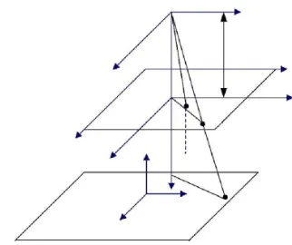
between coordinate system and the world coordinate [image:4.595.218.379.168.303.2]system by using the attitude parameters。As it shown is Figure 6.
Figure 6 Camera calibration model that calibration board parallels to imaging plane
The transformation of coordinates from world coordinate system to camera coordinate system, OWXWYWZWto
C C C CX Y Z
O , is a rigid transformation in three-dimensional space. If set up R and T respectively be the rotation matrix and translation matrix, transformation formula would be:
(2)
Make a small rotation to camera according to right hand rule, then the rotation matrix using the Euler angle representation as:
(3)
In case that calibration board parallels (or approximated parallel) to cameral imaging plane, the values of
α
andβ
are very small, the following approximate formula can be thought as tenable:。 、
、
、
β
β
γ
γ
γ
β
≅1 sin ≅ cos ≅1sin =cos
In addition, product for
α
andβ
is infinitesimal, ignore it. The formula therefore can be expressed as:(4)
(5) In case ignore camera distortions, coordinate of image point in the image plane coordinate axis is PU(XU,YU),
coordinate of image point in the image plane coordinate axis is ( )
d d d X Y
P , , its position in computer frame save imaging is m(u,v),basic task of cameral calibration is to establish the defined relationship between
) , , ( w w w w X Y Z
P and m(u,v)[6].
Step 1: to initialize the internal parameters of the camera
Firstly, enter plane calibration board calibration target 3D coordinate and image coordinate, actually reading directly from images, using such calibration point to initialize camera internal parameters, get fc =[fα,fβ]initial value
and first key point ,pixel location CC ( equal to imaging center point)defined, initializing of tilt factors
α
-cand 5 distorsion factors (all value 0),among them fα = fα
,fβ = fβ
,α
,β
respectively are the two adjacent pixel centerdistance in camera X direction, Y direction, its unit is mm。
Step 2: to initialize the external parameters of camera.
First normatively processed with calibration target pixel coordinates and initialized parameters, then calculate the
homogeneous matrix A,
= 1 0 0 0 0 d f c e
A ,e and f from that are respectively the absolute value and average
value generated through affine regularization by four corners point in each small square in X,Y direction deviation , while c is the average value that generated through regularization by four corners point in each small square in X,Y direction , and d is the opposite number of product by e and f.
Use iteration method enables pixel re-projection standard deviation to reach a minimum. By the steepest descent method updates all the known internal and external parameters. Coordinate system transformation through initialized internal and external parameters can achieve objects coordinate of initial camera coordinate system. Transformation from object referencing coordinate system to camera coordinate system as:
(6)
In the formula, R is 3*3 rotation matrix; T is translation vector that expressed in matrix elements are respectively as:
(7)
(8)
Point coordinate after projection through small holes is P(a,b),a=x/z,b=y/z ,presuming that 2
2 2
b a
r = + ,the distorted projection point is Pd(xd,yd)
) 2 ) 4 ( ) 3 ( ) 5 ( ) 2 ( ) 1 ( 1
( 2 4 6 2 2
a r kc ab kc r kc r kc r kc a
) ) 4 ( 2 ) 2 )( 3 ( ) 5 ( ) 2 ( ) 1 ( 1
( 2 4 6 2 2
ab kc b r kc r kc r kc r kc b
yd = + + + + + + (10)
Turn itno pixel coordinate. The transformation formula is:
) 1 ( ) )( 1
( x y c f
xp = d +
α
d + (11)) 2 ( ) 1 ( y c f
yp = d + (12)
Therefore, the i camera projection process can be represented as a nonlinear function argument with a state
vector
φ
l.( )
1 1
1 l
,
x
=
f
φ
x
(13)The above point projection example is to project every joints in arms and connect into the line.
3.3 Formation of Arms model projection
However in actual operation, we haven’t gathered data in projected 3D images but directly project dots into 2D images, collected 2D image data, furthermore got some prediction features of arms model projection in discus throwing, like boundary points prediction etc. The grey features matching is derives from every joints from internal arms, images contour and boundary features that extracted match to contour and boundary points. As the video results showing, we learn that discus throwing motion projection be covered, which require us to deduct the covered projection points when sampling and calculating.
Residual spares is the form of objective function in Gaussian algorithm,
f x
( )
=
∑
r
i2( )
x
.Givenp
r
φ
∂
=
∂
bethe Jacobi matrix of residual vector function, while the iteration solving process for
min( ( ))
f x
is:1
1
(
)
(
)
t t
n n n n n
x
+= −
x
x x
−x r x
= +
x
q
(14)We define objective function Q the weighted array of three features objective function as:
(15)
In formula (15),
Q
1Q
2Q
3 are respectively represents as target function in grey features, contour features and boundary featuresPresuming that two contiguous frames color invariant, its objective function construction based on grey feature as;
{
x i
il,
=
1, 2, 3,...
}
be the local coordinates of all visible points under the i camera from arms surface at t timeframe. Givenx
it,1
t i
x
− be respectively projection coordinates of arms surface pointx
il at t and t-1 time frame. Letl
t andl
t−1 be respectively the captured images by i camera from t and t-1,we define objective function as: 1 2 1 1 1( )
( ( )
(
))
c n t tt t i t i i
i j
Q
φ
I x
I
−x
−= =
=
∑∑
−
(16)Discus throwing arms reconstruction figures can be got in this method ,that provide a scientific effective training and observation method for physical researchers and coaches in discus throwing.
CONCLUSION
Video images analysis and computer vision theory have been widely used in the reconstruction and projection of human motion, tracking athletes ’motion and trajectory from sports video, getting human motion model and calculating motion parameters, make it easy for physical educators to research athletes’ motion flaws, improve training level for the athlete’s in a scientific way, and achieve upgrading more quickly and effectively. In this paper,
1 1 2 2 3 3
( )
tanalyzing of basic technical movements in discus throwing, make research of discus force bearing and arms movement trajectory in rotation, targeted find out a method to improve discus movement velocity, that is maximum throwing distance would be obtained in the way of reducing proactive force of arms and trying to achieve the maximum discus horizontal velocity, thus provide a more scientific and effective method for discus throwing distance increasing research. In order to do arms discus throwing researching more vividly, apply computer vision to reconstruct arms movements, further connect into a line and finally form a 2D image, present referencing suggestions to relative researchers on tossing items.
REFERENCES
[1] Chen Shu. Research on video-based human motion tracking and reconstruction [D].Doctoral dissertation of Central South University, Dec.,2008
[2] Yang Feng etc. Journal of Biomedical Engineering. 2005.22(2):307~311
[3] Che Tan. Scientific Journals. 2007.6:498-499.
[4] Liu Guo’yi etc. Journal of system simulation. Feb.,2006
[5] Lee Xing’fei etc. Journal of Tianjin University.Sept.2002: 601-605.