Methods of Accelerated Tests of Advanced Multilayer
Metallic Materials with Internal Protector
Vladimir A. Grachev
1,*, Andrey E. Rozen
2, Yuri P. Perelygin
3, Sergey Yu. Kireev
4, Irina S. Los
2 1Frumkin Institute of Physical Chemistry and Electrochemistry, Russian Academy of Sciences, Moscow, 119071, Russia 2Department of Welding, Foundry and Materials Science, Faculty of Mechanical Engineering, Transport and Energy, Penza StateUniversity, Krasnaya St., Penza, 440026, Russia
3Department of Chemistry, Faculty of Natural Science, Penza State University, Krasnaya St., Penza, 440026, Russia 4Department of Mechanical Engineering and Transport, Penza State University, Krasnaya St., Penza, 440026, Russia
Copyright©2018 by authors, all rights reserved. Authors agree that this article remains permanently open access under the terms of the Creative Commons Attribution License 4.0 International License
Abstract
The paper estimates corrosion resistance of new multilayer metal materials with internal protector, in which the principle of tread pitting-protection isimplemented. Experimentally, using the
electron-microscopic method, the mechanism of corrosion destruction of layers is substantiated. The electrochemical and chemical methods of accelerated tests are proposed, which make it possible to determine the rate of corrosion destruction. The electrochemical method allows revealing the limiting stage of the process, calculating the mass index of corrosion and justifying the choice of the tread for this corrosive environment. The chemical test method makes it possible to quantify the effectiveness of the action of the inner tread and determine the relative index of corrosion resistance of the multilayer material compared with the monometallic material.
Keywords
Multilayer Metallic Materials, Corrosion, Pitting, Internal Protector, Accelerated Testing1. Introduction
The problem of pitting corrosion remains relevant over the past decades, which is associated with the widespread use of high-alloy steels and alloys in various industries. The main areas of research in this area are the development of new materials, the study of the behavior of industrial materials in various environments, the modeling of pitting and the development of new test methods.
One of the ways to solve the problem of protection against pitting corrosion is to create a new class of multilayer metallic materials with an internal protector [1, 2]. These materials contain layers that have different values of electrochemical potentials and form short-circuited galvanic cells. This architecture fundamentally changes the process of corrosion destruction of the material and provides a longer period of operation. The kinetics of the corrosive destruction of multilayer metallic material and
the mechanism of action of the inner protector require further study.
The use of new materials is impossible without the development of reliable methods of accelerated corrosion testing, adapted to this architecture.
Existing methods of accelerated pitting corrosion resistance tests [3-5] serve to estimate the corrosion rate of monometallic materials. According to GOST 9.912-89 and ASTM G48-11, the stability of steels and alloys is evaluated by the chemical method, which consists in determining the mass corrosion coefficient. In a thermostated vessel with
6% solution of FeCl3 ∙ 6H2O is placed on the sample for the indicated time. After soaking and removing corrosion products, we weigh and calculate the average conditional rate of pitting corrosion in terms of mass loss. Electrochemical tests in accordance with GOST 9.912-89 are carried out by determining the pitting resistance in measuring the potential for free corrosion. Calculate the basic and additional bases of pitting resistance.
In addition to standard test methods, private methods have been developed and patented. To identify the propensity of steels and non-ferrous metals to pitting corrosion, electrochemical methods are used that differ in the electrical circuit, the composition of the electrolyte, and the number of electrodes [6-8]. In [9], a method for computerized image processing of the investigated surface in the initial state and after exposure to the medium with a subsequent analysis of the growth dynamics of pitting was developed for the purpose of modeling and forecasting. The measured index is the perimeter, along which the equivalent diameter is determined, then the time of safe operation of the article is calculated with a known wall thickness. In [10, 11], methods for studying and predicting pitting corrosion based on surface 3D metrology were proposed to determine the rate of increase in linear dimensions and the depth of pitting.
action of the inner protector. At the same time, it does not allow us to evaluate the kinetic regularities and quantitatively estimate the corrosion rate of each layer separately by the gravimetric method.
In this article, methods of accelerated corrosion tests of multilayered metallic materials are proposed, designed to calculate quantitative indicators.
The purpose of this work is to study the peculiarity of the mechanism of corrosion of advanced multilayer metallic materials with an internal protector and to develop methods for their accelerated corrosion tests.
2. Theoretical Part
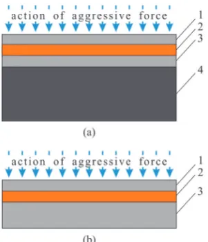
[image:2.595.99.250.469.644.2]This engineering approach is based on multilayer material comprised of components with different electrochemical potential; these components transform the corrosion processes upon transition from one layer to another. There is a transformation of corrosion damage from pitting corrosion in the upper layer to contact corrosion of the sacrificial layer. Pitting corrosion in the upper layer is transformed into contact corrosion of the preset sacrificial layer. In the case of unilateral impact of aggressive medium, four- and three-layer compositions are used. In case items operate under high internal or external loads and pressures, four-layer compositions are used (Fig. 1a). The first three layers provide corrosion protection of material, and the fourth layer is for mechanical strength. If the material is not exposed to significant loads, three-layer compositions are used. In this case the thickness of the third layer is determined by strength calculation (Fig. 1b) [17–21].
Figure 1. Schematic view of four-layer (a) and three-layer (b) metallic materials with internal protector: 1 – layer with high electrochemical potential, exposed mainly to pitting corrosion; 2 – layer with low electrochemical potential (“sacrificial layer” – internal protector); 3 – layer with high electrochemical potential; 4 – layer providing mechanical strength.
When multilayer material contacts with corrosive medium, the first layer is destroyed (Steel 08Kh18N10T – US analog AISI 321). Under certain conditions, in the
external layer there occurs pit nucleation and growth. When the first pitting reaches the middle layer, a short-circuited galvanic element is formed, in which the second layer material act as anode (Steel 10 – US analog M1010). With time, the second layer is exposed to corrosion damage, providing galvanic protection of the first and the third layers. In this case the pitting growth rate decreases since the pitting surface potential becomes negative. Herewith, instead of metal dissolution, on the pitting surface there occur reactions determined by the medium composition: in general case, Oxz+ + ze = Red. In particular, hydrogen evolution or oxygen reduction: 2H++2e = H2 in acid medium, 2H2O +O2 +4e = 4OH– in neutral and alkaline medium. On the surface of the second protecting layer, metal dissolution starts: M0 = M+z + ze. During simultaneous contact of the first, the second, and the third layer with corrosion medium, the galvanic protection will extend both to the first and the third layers.
Functioning mechanism and the protecting action radius of internal protector are determined by efficiency of the formed galvanic element, namely [13,14,22]:
1. the electromotive force (EMF) determined by the difference of material electrochemical potentials of the first and the second layers;
2. the corrosion current that depends on EMF and on the composition of corrosive medium inside pitting.
The composition of corrosion medium inside pitting can differ significantly from the composition of corrosion medium surrounding the multilayer material.
Generally, the rate of aforementioned reactions can be described as follows [22]:
𝑖𝑖𝑐𝑐=𝑧𝑧𝑐𝑐𝐹𝐹𝑘𝑘𝑐𝑐[𝑂𝑂𝑂𝑂𝑧𝑧+]𝑝𝑝exp(−𝛼𝛼𝑧𝑧𝑐𝑐𝐸𝐸𝐹𝐹 𝑅𝑅𝑅𝑅⁄ ), (1)
𝑖𝑖𝑎𝑎=𝑧𝑧𝑎𝑎𝐹𝐹𝑘𝑘𝑎𝑎exp(𝛽𝛽 𝑧𝑧𝑐𝑐𝐸𝐸𝐹𝐹 𝑅𝑅𝑅𝑅⁄ ). (2)
where ik and ia – current density of cathodic and anodic reactions, respectively, zc and za are the numbers of
electrons participating in cathodic and anodic processes, F is the Faraday constant, kc and ka are the constants of rate of
cathodic and anodic processes, [Oxz+] is the molar
concentration of oxidizer, p is the reaction order with respect to ions of oxidizer, α and β are the transfer coefficients of cathodic and anodic reactions, respectively, E is the compromise potential of the system “the first layer–the second layer”, R is the universal gas constant, T is the absolute temperature.
In the case of short circuited galvanic element, the cathodic current (Iс) equals to the anodic current (Ia):
Ic = Ia or Saia = Scic. (3) Sa is the surface area of protector, Sc is the cathodic surface
area, ia and ic are the densities of anodic and cathodic
currents.
Combined solution of Eqs. (1)–(3), with consideration that the potentials of protector and pitting metal are equal, results in the following equation:
ln𝑆𝑆𝑎𝑎 𝑆𝑆𝑐𝑐= ln
𝑧𝑧𝑐𝑐𝑘𝑘𝑐𝑐
𝑧𝑧𝑎𝑎𝑘𝑘𝑎𝑎+𝑝𝑝ln[𝑂𝑂𝑂𝑂
𝑧𝑧+]−𝐹𝐹𝐹𝐹(𝑧𝑧𝑐𝑐𝛼𝛼+𝑧𝑧𝑎𝑎𝛽𝛽)
From the Eq. (4) it follows that the ratio of surface areas of protector and cathodic surface depends on concentration of depolarizer, the ratio of rate constants of cathodic and anodic reaction and compromise potential which is between stationary potentials of the external layer material (Eex) and the protector material (Epr) in the considered
solution [13,14,22]. The more negative the stationary potential of protector is, the higher the ratio of surface areas of cathodic surface (Sс) and protector (Sa) is.
Analysis of equation (4) also makes it possible to assume that the radius of the protective action of the tread can be changed by selecting the materials of the first and second layers. And the potential of the second layer (the inner protector) is more negative, the more efficient the tread is.
In choosing a tread material in addition to electrochemical properties, it is necessary to take into account both mechanical, technological properties, as well as economic feasibility.
The obtained equation contains parameters that cannot be determined experimentally, but allows explaining the observed regularity of the corrosion behavior of a three-layer material at a qualitative level [17 ± 19].
It should be noted that the concentration of the depolarizer in the pitting time decreases with time, and the electroconductivity of the electrolyte decreases, which, accordingly, reduces the area of the protected surface. The pit can be filled with the protector dissolution products; as a result, the action of short circuited galvanic element ceases. New pitting centers are formed on the surface of the internal layer.
Compromise potential is determined by limiting stage running on cathode or anode [23]. Determination of the corrosion products composition allows us to establish the mechanism and sequence of corrosion destruction of the corresponding layers.
The existing accelerated testing methods, based on control of weight loss and pitting depth [24–26], do not provide accurate forecast of this integral materials’ behavior, which requires for new approaches.
3. Experimental Part
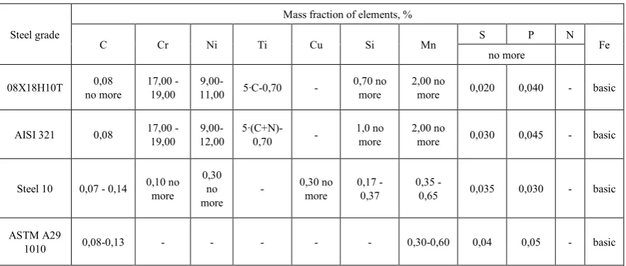
The principle of tread pitting protection was studied on a three-layer material of the composition 08X18H10T (analog AISI 321) + steel 10 (analog ASTM 1010) + 08X18N10T, obtained by explosion welding technology. The composition of steels and their analogs is indicated in Table 1 [21-25].
The technology of explosion welding is widely used for joining layers of a large area of a wide range of materials [26].
A qualitative assessment of the operability of the claimed principle was carried out on samples measuring 100 x 200 mm with a thickness of 2.0 mm layers cut from sheet material with an area of 9.0 m2. The samples were exposed to a solution of iron (III) chloride (density 1,049 ± 0,002 g / cm3) at a temperature of 23 ± 2°C [3].
[image:3.595.72.526.489.682.2]Electron microscopic studies were carried out using a FEI HELIOS NANOLAB 660 double-beam scanning electron microscope equipped with an attachment for the energy-dispersive micro-X-ray spectral analysis EDAX.
Table 1. Steels composition
Steel grade
Mass fraction of elements, %
С Сr Ni Ti Cu Si Mn S P N Fe
no more
08Х18Н10Т no more 0,08 17,00 - 19,00 11,00 9,00- 5∙С-0,70 - 0,70 no more 2,00 no more 0,020 0,040 - basic
AISI 321 0,08 17,00 - 19,00 12,00 9,00- 5∙(С+N)0,70 - - 1,0 no more 2,00 no more 0,030 0,045 - basic
Steel 10 0,07 - 0,14 0,10 no more 0,30 no
more -
0,30 no
more 0,17 - 0,37 0,35 - 0,65 0,035 0,030 - basic
ASTM A29
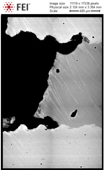
Fig. 2 shows the section of the longitudinal section of the deepest natural pitting with a cavity in the tread, and Fig. 3 shows mapped section of a three-layer sample under conditions where the corrosion processes reached the third layer.
Figure 2. Cross section of natural pitting of a three-layer sample under conditions where corrosion processes did not reach the third layer. 1 - the outer layer, 2 - the inner protector, 3 - the interlayer boundary, 4 - natural pitting, 5 - lens
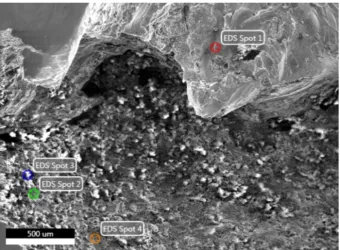
To study the mechanism and sequence of corrosion damage, a micro engine-spectral analysis of corrosion products was performed at individual points of the section. In Fig. 4 shows the cross section of the first and second layers. The elemental composition at the points is shown in Table 2.
[image:4.595.209.386.429.718.2]Figure 4. Sectional area of the first and second layers, forwhich the distribution of the elemental composition ofcorrosion products at points
Table 2. Elemental composition of corrosion products
Spot number Mass fraction of element, %
Fe O C Cr Ni Ti Si Al Mn Cl Cu Others
Spot 1 45,5 19,7 16 12 3,5 0,8 0,7 0,6 0,5 0,36 0 0
Spot 2 43,2 45,0 7,2 0,3 0 0 0,4 0,2 0 3,3 0 0,18
Spot 3 89,4 3,6 1,7 0,3 0 0 0 0 0,5 0,2 3,9 0,01
Spot 4 64,0 26,1 7,3 0,2 0 0 0 0 0,3 0,2 0 1,63
The electrochemical method was used in order to determine the corrosion rate for two metals contacting with corrosive medium. The method is based on a graphical analysis of the electrochemical corrosion rate and involves the measurement of the corrosion current density of contacting metals in multilayer material with an internal protector [27].
Polarization curves are constructed experimentally with the subsequent determination of the mass corrosion index of the components of the layers.
The samples are placed in a temperature controlled electric cell with the reference solution (Figure 5) and electrode potentials are measured in the absence of current in the circuit and at various resistances in the range of 1-100,000 Ohm. Minimum resistance is determined by the current of corrosion element.
Figure 5. Schematic view of the assembly for electrochemical study of corrosion elements and plotting of corrosion diagrams: 1 – electrodes made of multilayer composite’s components, 2 – reference electrodes, 3 – salt bridge, 4 – vessels filled with corrosive medium, 5 – tumbler, 6 – switch, 7, 9 – high resistance millivoltmeters, 8 – calibrated 1Ω resistor,
On the basis of the obtained electrode potentials and resistance, the corrosion current (I) was calculated and corrosion curve Eshe= f (I) was plotted, where Eshe is the metal potential with regard to standard hydrogen electrode. The experimental procedure was carried out on metal plates with the surface area of 2.00±0.05 cm2, made of sheet steel of the initial steel 08X18H10T and steel 10. The plates were partially isolated along the length with heat shrink tube in order to provide required surface area of the electrode and to prevent any contact of the metal surface with the “solution–air” phase interface. Then the surface was treated according to the standard procedure. With the tumbler deactivated, the electrode potentials were measured without current in circuit (stationary potential Est), which then were recalculated with regard to standard hydrogen electrode Eshe. Using the bank of resistors 10, the required electric resistance was adjusted. After closing the circuit by the tumbler 5, voltage drop on the calibrated resistor 8 was measured by the millivoltmeter 9. The obtained voltage was used for calculation of the current in the investigated circuit.
Fig. 6 illustrates corrosion diagram for the galvanic pair 08Kh18N10T – Steel 10. Iron chloride solution (III) was used as a testing medium (density 1.049±0.002 g/cm3).
[image:6.595.328.513.76.412.2]The chemical method was used to determine the rate of corrosion of each layer of a multylayer material. A method based on the use of demountable type samples was proposed [28]. The method consists in determining the mass index of corrosion of each plate imitating layers of a multilayer material with an internal protector.
Figure 6. Corrosion diagram for the galvanic pair 08Kh18N10T (curve 2) – Steel 10 (curve 1) in the iron chloride solution (III)
The objects of the test were:
1) collapsible multilayered metallic materials with internal protector in which the first and third layers are made of high-alloy steel 08X18H10T, and the inner second layer consisted of low-carbon steel 10;
2) comparison samples - plates representing separate layers of a multilayer material made of high-alloy steel 08Х18Н10Т and from low-carbon steel 10.
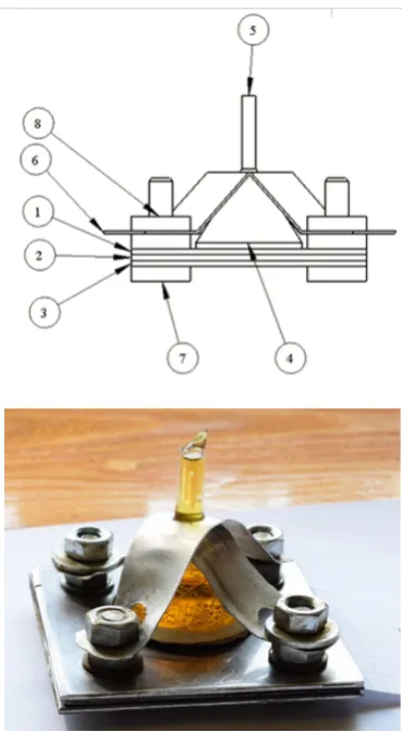
Figure 7. Schematic view (a) and appearance (b) of sample for testing: 1 – top plate, 2 – middle plate, 3 – bottom plate, 4 – separator, 5 – glass funnel, 6 – bracket, 7 – bolt, 8 – nut.
In the center of upper high alloy steel plate a through hole was made with the diameter of 1.0±0.2 mm (artificial pitting). In the center of low carbon steel plate a through hole was made with the diameter d, in such sequence: 3.0; 5.0; 10.0; 15.0 and 20.0 mm with the accuracy of ±0.1 mm. This range of diameters on one side should simulate the development of corrosion in the tread layer, shortening the test time by modeling the various stages and, on the other hand, determining the beginning of pitting formation in the third layer. The conditions of corrosion attack are more stringent than the natural development of the process, because allow to carry out corrosion influence on a material of a protective layer by a reagent of high activity. Under natural conditions, an increase in the diameter of the lens occurs due to anodic dissolution of the metal. The number of samples should provide the possibility of statistical processing of the results.
The plates were weighed with the accuracy of 0.0001 g. The plates were combined into a pack, the gaps between the plates around central hole were sealed. Glass funnels with the diameter of 36 mm were installed via inert separators on high alloy steel plates of each pack above artificial pitting. The funnel was additionally fixed with brackets (Fig. 6) and filled with iron chloride solution (III).
[image:6.595.61.289.450.616.2]of solution each 168±2 h without detaching of samples and removal of corrosion products.
After completion of each stage the packs were disassembled, washed with water, and dried, occurrence of pitting was examined visually.
Weight corrosion indices 𝐾𝐾𝑚𝑚− (g/m2⋅h) were calculated
on the basis of measurements for the upper, middle and bottom plates according to the equation:
𝐾𝐾
𝑚𝑚−=
[(𝑚𝑚01+𝑚𝑚02+𝑚𝑚𝜏𝜏∙(𝑆𝑆031+𝑆𝑆)−(2𝑚𝑚+𝑆𝑆113)+𝑚𝑚12+𝑚𝑚13)] (5) m01, m02, m03, m11, m12, m13 are the weights of plates in three parallel samples before and after testing, respectively, (g); τ is the exposure time (h); S1, S2, S3 is the cumulative surface contact area of plates for three parallel samples with corrosive medium (m2).The reference samples were tested under the same conditions and the same exposure time as the tests of three-layer samples including replacement of solution. After completion of each testing stage of reference samples, occurrence of pitting was visually examined on the high alloy steel plates, and then they were weighed.
The weight corrosion indices (𝐾𝐾𝑚𝑚−𝑟𝑟𝑟𝑟𝑟𝑟) of reference
[image:7.595.310.534.79.236.2]samples of low carbon and high alloy steels were calculated by Eq. (5); the calculations agree with the data in Table 1.
On the basis of experimental results, the weight corrosion index was plotted as a function of lens diameter for each plate of three-layer sample (Fig. 8).
(a)
(b)
[image:7.595.65.288.428.753.2](c)
Figure 8. Weight corrosion index of external (a), middle (b) and bottom (c) layer of metallic multilayer material at different diameter of artificial lens (d), diameter of artificial pitting of 1 mm and exposure time of 720 (curve 1) and 2,208 hours (curve 2).
4. Results Discussion
Electron microscope studies reveal the mechanism of corrosion processes and prove the effectiveness of the tread.
In Fig. 2 that anodic dissolution in the protector formed a cavity with transverse dimensions up to 5.0 mm. The dissolution boundary passed along the wave surface of the weld, at the point of contact of the first layer with the tread. The formation of the wave surface is characteristic of explosion welding technology. In the first layer, pitting with a diameter of 1.5 mm was formed under the influence of an aggressive medium.
This indicates that at the initial stage the corrosion damage of the outer layer is analogous to the damage to a monometal when exposed to an aggressive medium. Numerous pittings are formed on the surface.
When the second layer reaches the deepest pitting, the electrochemical interaction of the two layers with the aggressive medium begins, which changes the character of the corrosive destruction. Anodic dissolution of the tread proceeds more intensively at these contact points, forming lenses up to 5 mm in diameter. When the third layer is reached, the anodic dissolution of the tread develops in the transverse direction (Fig. 3).
apparently, is due to the lack of solubility of carbon in the test solution.
Thus, this method provides a qualitative assessment of the corrosion processes occurring in a multilayered metallic material with an internal protector, and confirms the mechanism of action of the tread. Nevertheless, it does not allowed to quantify the rate of destruction of layers of a multilayer material under conditions of through damage to the outer layer.
The application of the electrochemical method made it possible to construct a corrosion diagram (Fig. 6).
As it follows from the diagram, the potential difference between the electrodes made of 08Х18Н10Т and 10 steel with an open circuit is about 500 mV. As the magnitude of the external resistance decreases, the current increases and the potentials shift. The change in the potential of 08Х18Н10Т steel in the negative range is about 330 mV, and steel 10 in the range of positive values is about 150 mV. The magnitude of the corrosion current Icor is 45 mA.
[image:8.595.60.288.426.488.2]The processing of experimental data for the purpose of calculating the degree of anodic, cathodic and ohmic control allows us to conclude that in the test solution the degree of cathodic control of the corrosion process is more than twice the total value of the degree of anodic and ohmic control. The cathodic process is the limiting one. The results of calculations using the formulas recommended in [23] are given in Table. 3.
Table 3. The control degree of the galvanic pair 08X18H10T – steel 10
Degree of control Value, %
Degree of cathode control Ck 68,2
Degree of anode control Cа 30,7
Degree of ohmic control CR 1,1
The developed method allows to determine the absence of anodic passivation of the protector at the design stage of a multilayered material with an internal protector and to experimentally substantiate the choice of layer materials.
The application of the chemical method makes it possible to determine experimentally the values of the mass corrosion indices of each layer separately. As can be seen in Fig. 7a, the weight corrosion index of external layer increases with increase in the hole diameter in protector from 0.22 to 0.25 g/(m2⋅h) at exposure in 720 h, and from 0.18 to 0.19 g/(m2⋅h) in 2,208 h. This can be attributed to increase in the thickness of diffusion layer. Increase in exposure time of sample leads to decrease in corrosion rate of external layer in 1.2-1.4 times, which can be stipulated by partial filling of pitting cross section with low soluble products resulting from dissolution of protector.
The weight corrosion index of the middle layer (Fig. 7b) decreases with increase in the hole diameter from 1.76 to 0.13 g/(m2⋅h) in 720 h and from 0.90 g/(m2⋅h) almost to 0 in 2,208 h. With increase in exposure time, the anodic dissolution rate of protector decreases, which is stipulated by filling of pitting pore and artificial lens with the
products of protector dissolution, and by decrease in concentration of oxidizers in the lens.
The weight corrosion index of the third layer (Fig. 7c) decreases from 0.25 to 0.003 g/(m2⋅h) at exposure time of 720h. Increase in exposure time to 2,208 h leads to decrease in 𝐾𝐾𝑚𝑚− from 0.19 g/(m2⋅h) to 0. This is stipulated
by variation in composition of the corrosive medium above internal surface of the third layer.
The following conclusions can be made on the basis of analysis of the fourth method:
1) External inspection of the samples has demonstrated that with the diameter of artificial pitting in the first layer equaling to 1 mm and the diameter of artificial lens in protector (the second layer) from 3.0 to 20.0 mm, dissolution of both the first and the second layers is observed. Formation of new pitting centers is observed on the surface of the first layer.
At small diameters of the lens in the second layer, the values of the mass corrosion index of the first and third layers practically do not differ, i.e. Protector equally effectively protects them from corrosion.
As the diameter of the lens increases, the effectiveness of the protective action of the tread on the first layer decreases, which is explained by the increase in the distance from the tread wall to the outer surface of the first layer, and the mass corrosion index of the third layer decreases significantly, which is explained by the increasing role of the diffusion limitations of the process, the difficulty in delivering dissolved oxygen , as well as an increase in the area of the tread.
2) The corrosion rate of external layer of the multilayer material under considered conditions is by 58-66 times lower than that of the reference samples, thus proving the protector efficiency.
Corrosion failure of a multilayer metallic material in the presence of pitting in the outer layer proceeds in different concentration-diffusion conditions compared to monometallic. As the inner layer-protector dissolves and the size of the lens grows, the thickness of the diffusion layer increases, which means the distance from the outer surface of the outer layer to the wall of the tread. The latter, as well as the formation of poorly soluble products resulting from the dissolution of the tread, should obviously lead to a slowing down of the tread dissolution process and the resumption of the formation of new pittings on the outer layer.
begins in the third layer at the time of through destruction of the monometallic material at condition of equal thickness.
RI = (t_1 + t_2) / t_m (6) where t1 is the through breaking time of the first layer; t2 - the time of destruction of the material of the second layer to the size of the lens at which pitting starts in the third layer; tm - the time of through destruction of the monometallic material.
According to the data of [15], the mass corrosion index of the material of the first layer (steel 08X18H10T) in the solution of iron (III) chloride is 14.5 g / (m2 · h), the second layer (steel 10) in contact with the material of the first layer - 158.7 g / (m2 · h).
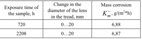
[image:9.595.61.290.519.582.2]To calculate the through-destruction of the first layer, the material of the first layer in the FeCl3 solution was used. The calculations were carried out at a pitting diameter of 1 mm and a depth of 2 mm. At the indicated values, the time t1 was 131.8 hours. To calculate the growth time of the lens in the second layer to a diameter of 20 mm, the average value of the material of the second layer in a solution of FeCl3-6.9 g / (m2 · h). This value was obtained by integrating the dependence (Fig. 7b), in the range from d = 0 (g / (m2 · h)) to mm. The maximum lens diameter of 20 mm is selected from the experimental confirmation of the absence of pitting in the third layer. Further growth of the lens leads to a decrease in the effectiveness of the protective action of the inner protector and the beginning of the growth of pitting in the third layer. which agrees well with the results of [12]. The obtained value of the area under the curve was used to find the average value of the mass corrosion index by constructing a rectangle of the same area with the side mm. The results are shown in Table 4.
Table 4. The results of calculating the mass index of corrosion
Exposure time of the sample, h
Change in the diameter of the lens
in the tread, mm
Mass corrosion
m
K−, g/(m2*h)
720 0…20 6,88
2208 0…20 6,87
With these parameters, the dissolution time of the inner tread to the diameter of the 20 mm t2 lens is 5654.0 hours. The total dissolution time of the first and second layers (t1 + t2) is 5785.8 hours. Under the same conditions, the growth time of the pitting in the monomaterial (Steel 08X18H10T) with a diameter of 1 mm and a depth of 4 mm, tm would be 263.6 hours.
Thus, the relative index of corrosion resistance of a multilayer material is RI = 21.9.
5. Conclusions
A set of methods for accelerated testing of multilayer
metallic material with an internal protector is proposed, which allows experimentally to confirm the efficiency of the architecture of a multilayer composite in general and the effectiveness of the action of the tread in particular, and also to predict the resource of a material under specific conditions.
Electron microscopic examination of the material, after exposure in a corrosive environment, allows a qualitative assessment of the corrosion processes occurring in a multilayered metallic material with an internal protector and confirms the mechanism of action of the tread. However, it is impossible to quantitatively estimate the rate of destruction of the layers in conditions of through damage to the outer layer using this method.
The electrochemical method of corrosion testing of multilayer materials developed by the authors allows to establish the absence of anodic passivation of the protector at the design stage of a multilayered material with an internal protector and to experimentally substantiate the choice of layer materials.
The use of a chemical method based on the use of a collapsible model of a multilayer composite allows experimentally to determine the values of the mass indices of corrosion of each layer separately and to determine the corrosion resistance index of a multilayered material in comparison with a monometal. It is established that for the architecture of the multilayer material 08X18N10T + steel 10 + 08X18N10T, the relative indicator of corrosion resistance is 21.9 times higher than the resistance of the monometallic material 08Х18Н10Т.
The developed methods can be used to build the architecture of a multilayer material and determine the quantitative indicators of corrosion resistance in corrosive media of various compositions.
Acknowledgements
Funding: This work was supported by the Ministry of Education and Science of the Russian Federation (Project No. 10.6563.2017/8.9).
REFERENCES
[1] W. Mai, S. Soghrati, R.G. Buchheit, A phase field model for
simulating the pitting corrosion, Corros. Sci. 110 (2016) 157–166. https://doi.org/10.1016/j.corsci.2016.04.001. [2] J. Bhandari, F. Khan, R. Abbassi, V. Garaniya, R. Ojeda,
Modelling of pitting corrosion in marine and offshore steel structures – A technical review, J. Loss Prev. Process Ind. 37 (2015) 39–62. https://doi.org/10.1016/j.jlp.2015.06.008. [3] J. C. Velázquez, J. A. M. Van Der Weide, E. Hernández, H.
Electrochem. Sci. 9 (2014) 4129–4143.
[4] A. Valor, F. Caleyo, L. Alfonso, D. Rivas, J. Yallen, Stochastic modeling of pitting corrosion. A new model for initiation and growth of multiple corrosion pits, Corr. Sci. 49 (2007) 559–579.
[5] I. I. Reformatskaya, A. N. Podobaev, I. I. Ashcheulova, I. G.
Rodionova, A. A. Pavlov, A. N. Ryvkin, O.N. Baklanova,
Corrosion resistance of bimetals with cladding stainless steel layers in nearly neutral aqueous media, Prot. Met. and Phys. Chem. Surf. 42 (6) (2006) 521–525.
[6] I. I. Reformatskaya, A. N. Podobaev, E. V. Trofimova, I. I. Ashcheulova, Developing concepts of chromium function in the passivation and pitting of Fe-Cr alloys, Prot. Met. And Phys. Chem. Surf. 40 (3) (2004) 207–213.
https://doi.org/10.1023/B:PROM.0000028911.18712.02.
[7] R. T. Loto, Pitting corrosion evaluation and inhibition of stainless steels: A review, J. Mater. Environ. Sci. 6 (10) (2015) 2750–2762.
[8] M. Guzmán, R. Lara, Inhibition pitting corrosion of A-890-1B stainless steel in NaCl solution by 5-amino-1,3,4 - thiadiazole -2- thiol, Int. J. Electrochem. Sci. 9 (2014) 3491– 3500.
[9] N. Alharthi, El-S. M. Sherif, H. S. Abdo, S. Z. El Abedin,
Effect of nickel content on the corrosion resistance of iron-nickel alloys in concentrated hydrochloric acid pickling solutions, Adv. Mat. Sci and Eng. 2017 (2017). https://doi.org/10.1155/2017/1893672.
[10]I. H. Toor, Effect of Mn content and solution annealing
temperature on the corrosion resistance of stainless steel alloys, J. Chem. 2014 (2014). http://dx.doi.org/10.1155/201 4/951471.
[11]K. A. Udod, I. G. Rodionova, L. B. Pervukhin, Use of
corrosion-resistant steels alloyed with nitrogen as a bimetal cladding layer prepared by explosion welding, Metallurgist 7-8 (2016) 1–4.
[12]N. Hara, K. Hirabayashi, Y. Sugawara, I. Muto,
Improvement of pitting corrosion resistance of type 316L stainless steel by potentiostatic removal of surface MnS inclusions, Int. J. Corr. 2012 (2012). http://dx.doi.org/10.11 55/2012/482730.
[13]I. L. Rozenfel`d, Korroziya i zashchita metallov [Corrosion and protection of metals], Metallurgiya, Moscow, 1970. [14]N. D. Tomashov, G. P. Chernova, Teoriya korrozii i
korrozionnostoikie konstruktsionnye splavy [Theory of corrosion and corrosion resistant alloys], Metallurgiya, Moscow, 1986.
[15]A. E. Rozen, I. S. Los`, Yu. P. Perelygin, L. B. Pervukhin,
Yu. A. Gordopolov, G. V. Kiriy, P. I. Abramov, S. G. Usatyi,
D. B. Kryukov, O. L. Pervukhina, I. V. Denisov, A. A. Rozen, Multilayer material with enhanced corrosion resistance (variants) and methods for preparing same, Eurasian Patent 016878, issued June 30, 2012.
[16]A. E. Rozen, I. S. Los`, Yu. P. Perelygin, L. B. Pervukhin,
Yu. A. Gordopolov, G. V. Kiriy, P. I. Abramov, S. G. Usatyi,
D. B. Kryukov, O. L. Pervukhina, I. V. Denisov, A. A. Rozen, Multilayer material with enhanced corrosion resistance (variants) and methods for preparing same, Patent 10-1300674 KIPO, Reg. date: August 21, 2013.
[17]V. A. Grachev, A. Y. Rozen, Y. P. Perelygin, A.A. Rozen, Multilayer metal material with special properties and the
production technology, Res. J. Pharm. Biol. and Chem. Sci.
7 (5) (2016) 403–411.
[18]V. A. Grachev, A. Y. Rozen, G. V. Kozlov, A.A. Rozen, Mechanism of pitting corrosion protection of metals and alloys, Orient. J. Chem. 32 (2) (2016) 845–850.
[19]I. S. Los`, Yu. P. Perelygin, A. E. Rozen, S. Yu. Kireev, Mnogosloinye korrozionno-stoikie materialy [Multilayer corrosion resistant materials], second ed., PGU, Penza, 2015.
[20]Yu. P. Perelygin, A. E. Rosen, I. S. Los’, S. Yu. Kireev, A new corrosion-resistant multilayer material, Prot. Met. and Phys. Chem. Surf. 7 (50) (2014) 856–859.https://doi.org/10 .1134/S2070205114070132.
[21]I. S. Los`, Otsenka korrozionnoi stoikosti mnogosloinykh metallicheskikh materialov [Estimation of corrosion resistance of multilayer metallic materials], Voprosy materialovedeniya, 3 (87) (2016) 138–144.
[22]V. V. Scorceletti, Teoreticheskie osnovy korrozii metallov [Theoretical foundations of metal corrosion], Khimiya, Leningrad, 1973.
[23]N. D. Tomashov, N. P. Zhuk, V. A. Titov, M. A. Vedeneeva,
Laboratornye raboty po korrozii i zashchite metallov [laboratory works on corrosion and protection of metals], Metallurgizdat, Moscow, 1961.
[24]Russian Standard GOST 9.912–89, Unified system of corrosion and ageing protection. Corrosion resistant steels and alloys. Methods of accelerated tests for resistance to pitting corrosion, Izd. standartov, Moscow, 1990.
[25]BS EN ISO 11463:2008, Corrosion of metals and alloys.
Evaluation of pitting corrosion, first ed., 1995–12–15, International Organization for Standardization, 2008. [26]ASTM G48 – 11, Standard test methods for pitting and
crevice corrosion resistance of stainless steels and related
alloys by use of ferric chloride solution, Annual Book of ASTM Standards, Vol. 03.02, ASTM, West Conshohocken, PA, 1995.
[27]I. S. Los`, Yu. P. Perelygin, A. E. Rozen, I. L. Harina,
Voprosy issledovaniya korrozionnoi stoikosti mnogosloinykh materialov, poluchennykh svarkoi vzryvom [Studying corrosion resistance of multilayer materials produced by explosive welding], Tyazheloe mashinostroenie 6-7 (2013) 7–10.
[28]Yu. P. Perelygin, S. Yu. Kireev, I. S. Los`, A. E. Rozen, M. Yu. Panin, Device for electrochemical study of metal
corrosion, RU Patent 2533344, Bull. No. 32, 2014.
[29]H. H. Uhlig, R. W. Revie, Corrosion and corrosion control, John Willey & Sons, New York, Chichester, Brisbane,