item and our policy information available from the repository home page for further information.
Author(s): Watmon, Titus Bitek; Weerasinghe, Vijitha; Xiao, David
Title:Enhanced tool wear characteristics of carbide tool inserts having a novel surface structure
Year of publication:2010
ENHANCED TOOL WEAR CHARACTERISTICS OF
CARBIDE TOOL INSERTS HAVING A NOVEL SURFACE
STRUCTURE
Titus Bitek Watmon, Vijitha Weerasinghe, and David Xiao
School of Computing, IT and Engineering, University of East London
[email protected], [email protected], [email protected]
Abstract. This paper presents the result of an investigation into the cutting characteristics of
electrical discharge machined (EDMed) surface-modified carbide cutting tool inserts. The tool inserts were coated with Titanium Nitride (TiN) by physical vapour deposition (PVD) method. In this study, comparative cutting tests using TiN coated control specimens with no EDM surface structures and TiN coatedEDMed tools with a crater-like surface topography were carried out on mild steel. Various cutting speeds, up to an increase of 40% of the tool manufacturer‘s recommended speed were investigated. Thirty cuts (passes) were carried out for each inserts at the speeds investigated. After every five cuts (passes), microscopic pictures of the tool wear profiles were taken in order to monitor the progressive wear on the rake face and, on the flank of the insert. The power load was monitored for each cut using an on board meter on the machine. Results obtained confirmed advantages of cutting at all speeds investigated using EDMed coated inserts in terms of reduced tool wear. Moreover, the surface finish on the work-piece was consistently better for the EDMed inserts. It is therefore concluded, that TiN coated EDMed crater-like surface structure on tool inserts can considerably improve the tool performance.
Key words: Titanium Nitride (TiN), Tool life, Tool wear, Cutting tools
1. Introduction:
Today, coating of tools with hard substances such as Titanium Nitride (TiN), Titanium Carbide (TiC) and Aluminum Oxide (Al203) to improve the tribological properties of cutting tools for metal cutting is increasingly becoming very prominent. Substantial amount of research has been done on tool coatings and, according to Dobrzanski (2004) ‗Coating tools with TiN is known to reduce friction in tribological contacts and increases the abrasive wear resistance‘. In addition to the enhanced wear resistance, ‗TiN coatings can also provide oxidation resistance, especially at high temperatures‘ (Navinsek et al, 2001, Batista et al, 2002 and Cekada et al, 2002). Demand for high
were coated with Titanium Nitride (TiN) to a thickness of approximately 4 µm by physical vapor deposition (PVD). The coated tools were used for turning operations on a Hitachi Seiki Computer Numerical Control (CNC) Lathe machine with a constant surface speed programmed. Different cutting speeds were used while maintaining the same depth of cut of 1 mm, and feed rate of 0.28 mm/rev throughout the experiments. The work material was EN3 mild steel in the form of 75 mm diameter, 300 mm long round bar billets. Various cutting speeds, up to an increase of 40% of the tool manufacturer‘s recommended speed of 250 m/min were investigated.
2.
Experimental.
2.1 Methodology – general.
The experiments investigated tool based wear criteria (Flank and rake wear) and a work based wear criterion (Workpiece
surface finish) simultaneously. Control specimens i.e. plain TiN coated inserts and test specimens (EDMed inserts) were used. Cutting speeds investigated were as follows:-
1st. 250 m/min which was the
recommended cutting speed for the particular type of inserts to machine mild steel.
2nd. 325 m/min an increase of 30%.
3rd. 350 m/min an increase of 40% A total of 30 cuts / passes, 200 mm long each were carried out for each insert. After every 5 cuts, the tool wear profiles of the inserts were examined under a microscope and pictures taken in order to monitor the progressive wear on the rake and on the flank of the insert. At the same time, the work billet was removed from the machine, and the surface roughness measured at 0.8 mm cut off length. The power load was
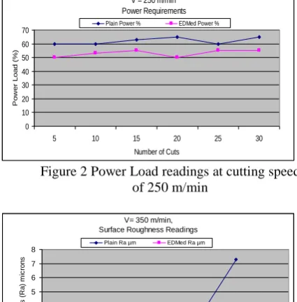
monitored for each cut using an on board meter on the machine. Surface roughness (Ra) measurements and power load readings at cutting speed of 250 m/min are shown in figures 1 and 2 respectively. Likewise, figures 3 and 4 show surface roughness (Ra) measurements and power load readings respectively for 350 m/min cutting speed.
V = 250 m/min, Surface Roughness Readings
0 0.5 1 1.5 2 2.5 3 3.5 4
5 10 15 20 25 30
Number of Cuts
S u rf a c e R o u g h n e s s ( R a ) m ic ro n s
[image:3.595.309.521.233.360.2]Plain Ra µm EDMed Ra µm
Figure 1 Workpiece Surface Roughness (Ra) measurements at 250 m/min
V = 250 m/min Power Requirements 0 10 20 30 40 50 60 70
5 10 15 20 25 30
Number of Cuts
Po w e r L o a d (% )
[image:3.595.309.522.404.621.2]Plain Power % EDMed Power %
Figure 2 Power Load readings at cutting speed of 250 m/min
V= 350 m/min, Surface Roughness Readings
0 1 2 3 4 5 6 7 8
5 10 15 20 25 27 30
Number of Cuts
Su rf a c e R o u g h n e s s (R a ) m ic ro n s
[image:3.595.312.522.556.696.2]Plain Ra µm EDMed Ra µm
Figure 3. Workpiece Surface Roughness (Ra) measurements after machining at 350 m/min
V= 350 m/min, Power Readings
0 10 20 30 40 50 60 70 80
5 10 15 20 25 27 30
Number of Cuts
Po
w
e
r
L
o
a
d
s
(%
)
[image:4.595.337.486.106.304.2]Plain Power % EDMed Power %
Figure 4 Power Load readings at cutting speed (V) of 350 m/min
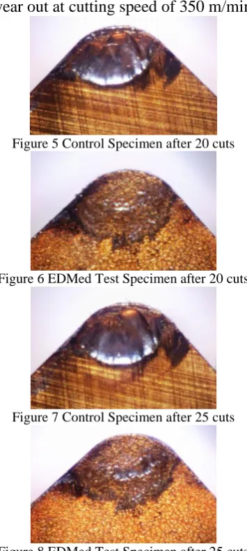
Figures 5 to 10 show the microscopic profiles of the tool as they progressively
wear out at cutting speed of 350 m/min.
Figure 5 Control Specimen after 20 cuts
Figure 6 EDMed Test Specimen after 20 cuts
[image:4.595.76.286.108.252.2]Figure 7 Control Specimen after 25 cuts
Figure 8 EDMed Test Specimen after 25 cuts
[image:4.595.91.269.303.699.2] [image:4.595.314.514.508.638.2]Figure 9 Control Specimen after 27 cuts
Figure 10EDMed Test Specimen after 30 cuts
3. Observations
3.1 Crater and Flank Wear
Crater wear is one of the factors that determine the life of a metal cutting tool. After some duration of cutting, cratering becomes so severe that the tool edge is weakened and eventually fractures. Crater wear develops on the rake face of the tool. Figure 11 below illustrates the different types of tool wear.
Figure 11, Types of wear on asingle point cutting tool.
3.2 Progressive Wear
The progressive wear of the tools took place in two different interesting ways as demonstrated in figures 5 to 11 above, and which can be summarised as crater and flank wear as follows:
(a) Wear on the rake face which developed as a crater resulting from the friction between the chip undersides rubbing along the tool rake face.
(b) Secondly, wear on the flank also developed at a point where a wear-land is formed by the rubbing action of the newly generated workpiece surfaces against the tool cutting point.
4. Discussion of Results
The results illustrate that wear on the rake face, (see figures 5 to 13), took place in the form of a crater away from the cutting edge, and in a zone where the temperature is known to be highest. Chips rubbing against the tool surface caused primary wear by abrasion, however, the EDMed surfaces have a much higher resistance to wear. Results also show that, TiN coating on the rake faces of the control specimens appeared to wear off after only a short duration of cutting, whereas the coating on the EDMed surfaces noticeably held for a much longer duration of cutting. Wallén and Hogmark, (1989) stated that ‗although, the coating is worn off by way of a crater, the remaining coating (along the rim of the wear scar) continues to offer resistance to wear’. Consistent lower power readings for EDMed specimens indicate lower friction forces. Considering the 350 m/min test results by way of example, whereas wear is visible after five cuts on the control specimen, wear
becomes visible after 15 cuts on the EDMed specimen, see Fig. 12 , 13 below.
[image:5.595.315.513.121.330.2]Figure 12 EDMed Test Specimen after 15 cuts
Figure 13 Control Specimen after 15 cuts
After 27 cuts the control specimen failed,
possibly due to excessive crater wear on the rake face and flank. See figures 14 and 15 below
Figure 14 Rake face Control Specimen after failing at 27 cuts.
Figure 15 The tool Flank Control Specimen after failing at 27 cuts
Although there is no visible wear on the rake face of the EDMed specimen after five cuts, but the surface on the cutting zone appeared ‗mottled‘.
[image:5.595.361.469.411.495.2] [image:5.595.343.478.530.614.2]corner radius and progresses along the cutting edge. Results show that flank wear on both control and the EDMed specimens was similar. The surface finish produced by the EDMed inserts was clearly better than those of the control specimens.
5. Conclusions:
The overall surface roughness measurements of the EDMed TiN coated inserts was particularly better for the 350 m/min cutting speed. This study indicates that, after 2.5 minutes of cutting, a substantial wear-land becomes visible on the rake face of the control specimen whereas, even after 7.7 minutes of cutting, there wasstill no visible wear-land on the EDMed rake face of the test specimens. This is significant because it indicates possibility of higher tool life by way of tool wear compensation. Moreover, the EDMed inserts operated at up to 18% reduced power consumption.
6. Acknowledgements:
The authors acknowledge support from the following companies; Newport Engineering in Harlow, Essex for providing their EDM machines, Newton Equipment Limited in Barking, Essex, for making available their CNC Machines used for the cutting Tests, and finally, Imperial Innovations Limited, London and Kyambogo University, Uganda for financial support.
7. References:
Batista J, C, A, Joseph, M, C, Godoy, C, Mathews, A, (2002), Micro-abrasion wear testing of PVD TiN coatings on untreated and plasma nitrided AISI H13 steel. Journal
of Wear, Vol, 249 pp971 – 979.
Cekada, M, Panjan, P, Macek, M, Amid, P, (2002), Comparison of structural and chemical properties of Cr-based hard coatings, Journal of Surface Coatings
Technology, Vol. 151 -152 pp31 – 35.
Dechjarern S, (2002) Study of the friction and wear behaviour of a coated cutting tool, with different surface topographies, PhD
Thesis –Imperial college , London, UK
Dobrzanski, L.A, Polok M, Panjan, P, Bugliosi, S, Adamiak, M, (2004), Improvement of wear resistance of hot work steels by PVD coatings deposition, Journal
of Materials Processing Technology, Vol.
155-156 pp1995-2001.
MacGinley T., and Monaghan J., (2001),
Journal of Materials Processing Technology
vol. 118, page 293 -300.
Navinsek, B, Panjan, P, Uranian, I, Vahte, P, Gorenjak, F, (2001), Improvement of hot-working process with PVD coatings and duplex treatment, Journal of Surface
Coatings Technology, Vol. 142-144 pp1148-
1154.
Wallén, P and Hogmark, S, (1989), Influence of TiN coating on wear of high speed steel at elevated temperature, Journal