Design and Analysis of Boiler Shell with Fastened Joints
N K H Sameera
1P Poorna Mohan
2K Subbarao
31
M. Tech. Student
2Senior Assistant Professor
3Head of Dept.
1,2,3Department of Mechanical Engineering
1,2,3
Godavari Institute of Engineering and Technology, Rajahmundry 533296, Andhra Pradesh India
Abstract— With the increase in the development and rise in the growth of population, there is also rise in the power consumption and usage. The development of technology in the area of boilers and pressure vessels have reached a level of technological maturity. However, the increase in the rise of technology also increased the challenges in the design of boilers and pressure vessels. One of the biggest challenges is to design a boiler for high-temperature applications which can withstand major boiler problems like stress corrosive cracking (SCC) and thermal losses due to conduction and convection phenomenon. This paper aims at designing a geometry for boiler shell which can operate at optimal conditions of Ultra-supercritical thermal power plants and analyse the design with advanced alloys like X38CrMoV5-3 alloy and Inconel 625 which can operate at high temperatures and resistive to sulphidation, slagging and corrosion and compare the results with alloy steel which is used in the production of boiler shells currently in the market. Bolted joints are used in the design in order to reduce the SCC on welded joints. The design of boiler shell is carried out in Solidworks Part Design and the analysis of boiler shell is carried out in Solidworks Simulation.
Key words: Alloys, Alloy Steel, Boilers, INCONEL® 625, Power Plant, Simulation, SCC, Sulphidation, Steam Turbine, X38CrMoV5-1 Alloy
I. INTRODUCTION
Pressure vessels and boiler shell applications in power plants in both thermal power plants and nuclear power plants are rising day by day as the need for electricity are being increased with the growth of the population of human beings. The development of pressure vessels and boiler shells have reached a level of technological maturity. However, the largest design considerations of boiler shells are the geometry which should withstand and operate at optimal operating conditions of the boiler for longer periods by sustaining the wear and tears caused due to sulphidation, stress corrosive cracking, etc. The damaged boiler shell also affects the performance of power plant and sometimes also results in catastrophic explosions which the world has witnessed many times since the past.
In this paper, we detail the procedure for the design of boiler shell and the analysis procedure of boiler shell for the operating condition of Ultra-supercritical thermal power plants by using advanced alloys like INCONEL® 625 and X38CrMoV5-1 and present a new geometry for the boiler shell. The procedure for analyzing the effects of pressure and temperature on the boiler shell which are formed during combustion process due to which the boiler shell life is affected is also discussed.
II. GOVERNING EQUATIONS
The method used in the structural simulation analysis of designs in Solidworks Simulation is the Finite Element Analysis (FEA).
Finite Element Analysis used in simulation packages or solvers generally comprises of three steps. They are as follows:
A. Pre-processing
In this step, the finite element mesh for the designed model is developed and boundary conditions, material properties, and loads are applied to the designed model.
B. Solution
In this step, the problem is solved for the given loads and boundary conditions. The results such as Von Mises stress, strain, displacements, thermal effects, etc., are obtained in this step.
C. Post-processing
In this step, the results are visualized in the form of contours, deformed shapes, and plots. This step helps in the debugging, verification and validation of results.
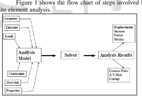
[image:1.595.317.544.413.567.2]Figure 1 shows the flow chart of steps involved in finite element analysis.
Fig. 1: Finite Element Analysis flow chart
III. MATERIAL PROPERTIES
High-temperature alloys are the materials used in this study. The three alloys used are:
Alloy Steel INCONEL® 625
X38CrMoV 5-3
Properties Alloy Steel INCONEL ®
625
X38CrMoV 5- 3 Yield
strength
6.2042e+008 N/m2
7.58e+008 N/m2
2.12e+009 N/m2 Tensile
strength
7.2382 e+008 N/m2
1.103e+009 N/m2
2.12e+009 N/m2 Elastic
modulus
2.1e+011 N/m2
2.048e+011 N/m2
Poisson's
ratio 0.28 0.312 0.28
Mass
density 7700 kg/m
3 8440 kg/m3 7850 kg/m3
Shear modulus
7.9e+010 N/m2
7.8e+010 N/m2
7.9e+010 N/m2 Thermal
expansion coefficient
1.3e-005 /Kelvin
1.31e-006 /Kelvin
1.1e-005/Kelvin
Table 1: represents the material properties.
IV. METHODOLOGY
Boiler shell designed in Solidworks Part design and assembled in Solidworks Assembly. Solidworks Simulation is used to analyze the model.
A. The Design of the Boiler Shell
In Figure 2, a component of the boiler shell design is shown. The boiler shell component in the figure is represented the standard isometric view.
Fig. 2: Boiler Shell Component Isometric View Table 2 represents the volumetric properties of the models of the boiler shell component.
Design With Alloy
Mass (kg)
Volume (m3)
Density (kg/m3)
Weight (N)
Alloy Steel 91439.1 11.8752 7700 896103
INCONEL®
625 100227 11.8752 8440 982222
X38CrMoV
5-3 93220.4 11.8752 7850 913559
Table 2 Volumetric properties of the models of the boiler shell component
In Figure 3, an assembly of the boiler shell design is shown. The boiler shell assembly in the figure is also represented the standard isometric view.
Fig. 3: Boiler Shell Assembly Isometric View Table 3 represents the volumetric properties of the models of the boiler shell assembly.
Design With Alloy
Mass (kg)
Volume (m3)
Density (kg/m3)
Weight (N)
Alloy Steel 182878.2 23.7504 7700 1792206
INCONEL®
625 200454 23.7504 8440 1964444
X38CrMoV
5-3 186440.8 23.7504 7850 1827118
Table 3: Volumetric properties of the models of the boiler shell assembly
B. The meshing of Models
Table 4 represents the type of mesh, element types used in the meshing, number of Jacobian points and type of solver used in the simulation analysis of boiler shell in Solidworks Simulation software.
Mesh Type Solid mesh
Mesh Element Type Tetrahedron
Jacobian points 4
Solver type FFEPlus
Table 4: Type of mesh, element types used in the meshing, number of Jacobian points and type of solver used in the
simulation analysis of boiler shell
Detailed meshing information is given in part c of this chapter.
C. Meshing information of Boiler Shell
Tables 5, 6 and 7 gives the detailed meshing information of the boiler shell assembly during analysis using Alloy Steel, INCONEL® 625 and X38CrMoV 5-3.
1) Analysis with Alloy Steel
Mesh Details Static 1 Static 2
Mesh type Solid mesh Solid mesh
Mesh Element Type Tetrahedron
on Tetrahedron
Jacobian points 4 4
Element Size 143.706 mm 143.884 mm
Tolerance 7.18531 mm 7.1942 mm
Total Nodes 136483 136275
Total Elements 83649 83489
Maximum Aspect Ratio 12.284 12.284
Table 5: Analysis with Alloy Steel
2) Analysis with INCONEL® 625
Mesh Details Static 1 Static 2
Mesh type Solid mesh Solid mesh
Mesh Element Type Tetrahedron
on Tetrahedron
Jacobian points 4 4
Element Size 143.706 mm 143.884 mm
Tolerance 7.18531 mm 7.1942 mm
Total Nodes 136483 136275
Total Elements 83649 83489
Maximum Aspect Ratio 12.284 12.284
Table 6: Analysis with INCONEL® 625
3) Analysis with X38CrMoV 5-3
Mesh Details Static 1 Static 2
Mesh type Solid mesh Solid mesh
Mesh Element Type Tetrahedron
on Tetrahedron
Jacobian points 4 4
Element Size 143.706 mm 143.884 mm
Tolerance 7.18531 mm 7.1942 mm
Total Nodes 136483 136275
Total Elements 83649 83489
Maximum Aspect Ratio 12.284 12.284
This is the detailed information of the meshing of boiler shell assembly.
V. RESULTS AND DISCUSSIONS
The simulations and Finite Element Analysis on the boiler shell assembly which is done considering the materials Alloy Steel, INCONEL® 625 and X38CrMoV 5-3 alloy results in Von Mises stress. The obtained results are shown below:
A. Static 1
In the static 1 study, the load that causes a force on the boiler shell assembly is due to acceleration due to gravity and the value of the load is equal to mg on the boiler shell where m is total mass of the boiler shell and fasteners. This load is used in static 1 analysis. Fixed supports are used as fixtures at the base support provided at the bottom of the boiler shell on which the complete weight of the boiler shell, it's components, and mounting of the boiler acts. The results of the analysis in a static study on the boiler shell with Alloy Steel, INCONEL® 625 and X38CrMoV 5-3 alloy are shown in Table 8.
The test conditions and the criterion for the analysis are:
Mass of the boiler assembly which is equal to m = 182878.2 kg and acceleration due to gravity which is equal to g = 9.8 m/s2 causesthe load 1792206 N on the boiler shell.
Von Mises stress failure criterion is used in the static 1 study.
Design With Alloy
Von Mises Stress (min)
Von Mises Stress (max)
Alloy Steel 9.975e+002 N/m2 3.682e+007 N/m2
INCONEL®
625 1.142e+003 N/m
2 3.478e+007 N/m2
[image:3.595.310.548.53.115.2]X38CrMoV 5-3 1.031e+003 N/m2 3.679e+007 N/m2 Table 8: Von Mises stress failure criterion is used in the
static 1 study.
B. Static 2
In static 2 study the loads on the boiler shell are due to force caused by the gravity which causes the load mg, the pressure exerted by the gases on the walls of the boiler shell from the inside of the shell as a result of the combustion of fuel during combustion phase during the plant operating timings and the thermal load effects caused by the heated fluids on the boiler shell during combustion phase. Fixed supports are used as fixtures at the base support provided at the bottom of the boiler shell on which the complete weight of the boiler shell, it's components, and mounting of the boiler acts. The results of the analysis in a static study on the boiler shell with Alloy Steel, INCONEL® 625 and X38CrMoV 5-3 alloy are shown in Table 9.
Mass of the boiler assembly which is equal to m = 182878.2 kg and acceleration due to gravity which is equal to g = 9.8 m/s2 causesthe load 1792206 N on the boiler shell. A thermal load such as temperature T = 800º C and pressure load P = 100 N/mm2 are applied in static 2 studies.
Von Mises stress failure criterion is used in the static 2 study.
Design With Alloy
Von Mises Stress (min)
Von Mises Stress (max)
Alloy Steel 4.571e+004 N/m2 2.887e+009 N/m2
INCONEL®
625 1.777e+004 N/m
2 1.841e+009 N/m2
X38CrMoV
5-3 2.802e+004 N/m
2 1.453e+009 N/m2
Table 9: Von Mises stress failure criterion is used in the static 2 study.
Von Mises stresses are the results obtained from simulations done on boiler shell using Solidworks Simulation. Plots obtained in the studies static 1 and static 2 are plotted and are shown below.
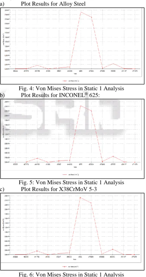
1) Static 1
The plots are plotted against nodes and Von Mises stress. Plots for Von Mises stress are obtained at different nodes using Probe tool in Static 1 study.
[image:3.595.307.555.228.698.2]a) Plot Results for Alloy Steel
Fig. 4: Von Mises Stress in Static 1 Analysis b) Plot Results for INCONEL® 625:
Fig. 5: Von Mises Stress in Static 1 Analysis
c) Plot Results for X38CrMoV 5-3
Fig. 6: Von Mises Stress in Static 1 Analysis 2) Static 2
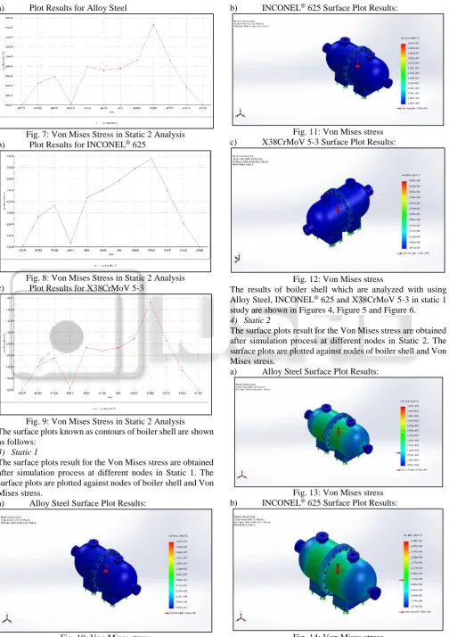
[image:3.595.49.286.363.485.2]a) Plot Results for Alloy Steel
Fig. 7: Von Mises Stress in Static 2 Analysis b) Plot Results for INCONEL® 625
Fig. 8: Von Mises Stress in Static 2 Analysis
[image:4.595.283.550.51.377.2]c) Plot Results for X38CrMoV 5-3
Fig. 9: Von Mises Stress in Static 2 Analysis The surface plots known as contours of boiler shell are shown as follows:
3) Static 1
The surface plots result for the Von Mises stress are obtained after simulation process at different nodes in Static 1. The surface plots are plotted against nodes of boiler shell and Von Mises stress.
a) Alloy Steel Surface Plot Results:
Fig. 10: Von Mises stress
b) INCONEL® 625 Surface Plot Results:
Fig. 11: Von Mises stress c) X38CrMoV 5-3 Surface Plot Results:
Fig. 12: Von Mises stress
The results of boiler shell which are analyzed with using Alloy Steel, INCONEL® 625 and X38CrMoV 5-3 in static 1 study are shown in Figures 4, Figure 5 and Figure 6.
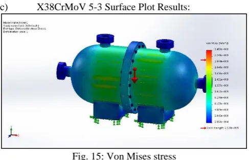
4) Static 2
The surface plots result for the Von Mises stress are obtained after simulation process at different nodes in Static 2. The surface plots are plotted against nodes of boiler shell and Von Mises stress.
a) Alloy Steel Surface Plot Results:
Fig. 13: Von Mises stress b) INCONEL® 625 Surface Plot Results:
[image:4.595.44.293.55.523.2] [image:4.595.35.556.406.748.2]c) X38CrMoV 5-3 Surface Plot Results:
Fig. 15: Von Mises stress
The results of boiler shell which are analyzed with using Alloy Steel, INCONEL® 625 and X38CrMoV 5-3 in static 2 studies are shown in Figures 7, Figure 8 and Figure 9.
C. Interpretation of Results
The computer simulations in both the static 1 and in the study 2 studies on the boiler shell resulted in minimum Von Mises stress and maximum Von Mises stress. The values maximum Von Mises and the minimum Von Mises stress are very less compared to the YieldstrengthofAlloy Steel, INCONEL® 625 and X38CrMoV 5-3 alloy in static 1 study. Hence the designs are considered to be successful.
VI. CONCLUSION
A. Conclusions
The designs are successful since in the computed results in Static study 1 show that the Von Mises stress for the boiler shell is under the yield point of the material.
The minimum and maximum values of Von Mises stress for the both studies, Static studies 1 and 2 using the Alloy Steel, INCONEL® 625 and X38CrMoV 5-3 alloy varies. In Static 1 study, the alloy INCONEL® 625 has the least maximum Von Mises Stress value 3.478e+007 N/m2 which is lessthan X38CrMoV 5-3 alloy, 3.679e+007 N/m2 and Alloy Steel, 3.682e+007 N/m2. In this case, INCONEL® 625 is superior compared to X38CrMoV 5-3 alloy and Alloy Steel.
But the boiler shell results in Static 2 study conducted considering the operating conditions of an Ultra-supercritical thermal power plants, the boiler shell designed with the Alloy Steel starts yielding since the maximum Von Mises Stress, 2.887e+009 N/m2 far exceeded the yield stress value, 6.204e+008N/m2 at the test conditions which indicates that it cannot sustain at the optimal operating conditions.
On the other hand, the results of the Static 2 study conducted at the same operating conditions of Ultra-supercritical thermal power plants shows that the boiler shell designed with the INCONEL® 625 starts yielding since the maximum Von Mises Stress, 1.841e+009 N/m2 far exceeded the yield stress value, 7.58e+008 N/m2. This indicates that even the alloy INCONEL® 625 did not sustain. To make the boiler shell sustain with the alloy INCONEL® 625 needs an increase in the thickness of the boiler shell which results in a lot of investment.
The Static 2 study conducted considering the X38CrMoV 5-3 alloy is successful since the maximum Von Mises Stress, 1.453e+009 N/m2 does not exceed the yield stress value, 2.12e+009 N/m2.
Therefore, the study gives the following conclusions that the boiler shell designed with the X38CrMoV 5-3 alloy can be used in the boiler shell which can sustain under the optimum working conditions of Ultra-supercritical thermal power plants.
REFERENCES
[1] John P Moore, “Horizontal Shell Boiler,” United States Patent, Patent No.: 4,409,926.
[2] Stanley G Finch, “Boiler,” United States Patent, Patent No.: 4,909,190.
[3] John P Moore, “Shell Boilers,” United States Patent, Patent No.: 4,308,826.
[4] Martti Seppanen, Johan Ruotsala, “Boiler Plant a Support Structure and a Method for Supporting the Walls of a Steam Boiler of a Boiler Plant,” United States Patent, Patent No.: US 2008/0276885 Al.
[5] Dewan Shamsuz Zaman, “Boiler Structure and Method of Assembly,” United States Patent, Patent No.: US 2015/0241054 Al.
[6] Kazuya Yamada, Tetsuji Namato, Hidetomo Saimi, “Boiler System,” United States Patent, Patent No.: US 2015/0204537 Al.
[7] R. Viswanathan, W. Bakker, “Materials for Ultrasupercritical Coal Power Plants—Boiler Materials: Part I,” JMEPEG (2001), Volume 10, Page No.:81-95. [8] R. Viswanathan, W. Bakker, “Materials for
Ultrasupercritical Coal Power Plants—Boiler Materials: Part II,” JMEPEG (2001), Volume 10, Page No.: 96-101. [9] R. Viswanathan, J.F. Henry, J. Tanzosh, G. Stanko, J. Shingledecker, B. Vitalis, R. Purgert, “U.S. Program on Materials Technology for Ultra-Supercritical Coal Power Plants,” JMEPEG (2005), Volume 14, Page No.:281-292