Wireless Mesh Networks Topology Auto Planning
Tarik MOUNTASSIR
1, Bouchaib NASSEREDDINE
1,3, Abdelkrim HAQIQ
1, 2, Samir BENNANI
31
Computer, Networks, Mobility and Modeling laboratory FST, Hassan 1st University, Settat, Morocco
2
e-NGN Research group, Africa and Middle East
3
RIME Laboratory, Mohammadia Engineering School Agdal Rabat, Morocco
ABSTRACT
Wireless mesh networks have seen a real progress because of their implementation at a low cost. Thus, the planning of such networks presents many challenges for network operators. Our aim in this paper is to provide a new solution to the planning problem using a multi-objective optimization approach.
Keywords
Wireless Mesh Networks, Planning, Improvement, Capacity, Multi-Objective Optimization, Topology
1.
INTRODUCTION
Wireless Mesh Networks (WMNs) are a class of Next-Generation Networks (NGN) that provides one of the most promising solutions to improve network coverage, deliver community broadband Internet access services and reduce deployment cost. In such networks, communications between two nodes can be supported by intermediate nodes called Mesh Routers (MRs). Fig.1 illustrates a relatively static infrastructure of a WMN composed by three types of wireless routers. The routers which connect the clients to the requesting service are called Access Points (APs). The relays route the traffic to other relays via a point-to-point connection until a router with an Internet connection is found. Such a wireless router is called a Mesh Gateway (MG) [1].
To further allow simultaneous communications and improve the capacity of mesh networking, a mesh router is usually equipped with multiple wireless interfaces built on either on the same or different wireless access technologies.
[image:1.595.316.548.225.423.2]WMNs have been deployed in diverse environments such as home networks, companies and universities. Such networks can also serve the purpose of temporary infrastructure in disaster and emergency situations or in various control system such as public area surveillance. However, these applications continue to confront the problems of connectivity and performance caused by poor planning of wireless networks. In the last six years, considerable interest has been given to the problems of designing WMNs. Most of these studies has focused on routing [2], interference measurement and capacity analysis [3], power control [4], topology control [5], link scheduling [6] and channel/radio assignment [7]. However, few studies have addressed the placement of nodes in the network.
Fig 1: Infrastructure of a WMN
In this paper, we consider the planning of Radio Multi-Channel WMNs and we focus on the nodes placement. Thus, our contribution can be summarized as follow:
We considered all parameters that influence the design result including: Deployment cost, client coverage, channels assignment, flow routing, network capacity, interference, robustness and load balancing.
We proposed a new model for the problem of WMNs planning where the three conflicting objectives are optimized simultaneously; minimizing the cost, maximizing the coverage and the throughput improvement (by balancing the load on the links). To resolve this problem, we used a meta-heuristic in
order to obtain optimal results and allowing the planner to choose the one that satisfies his budget.
The rest of the paper is organized as follow: Related works are presented in Section 2. We present the formulation of our model in Section 3. In Section 4, we describe a multi-objective optimization of the proposed model. Section 5 presents experimental results. We conclude our work and give directions for future research in Section 6.
Wired link
Wireless link
MG
MR
AP
INTERNET
2.
RELATED WORKS
Many formulations and algorithms have been proposed for WMNs planning. The authors of [8], [9], [10] optimized the placement of MRs (i.e. the backbone WMNs) to provide large coverage to clients at a minimum cost while granting good performances and a minimum level of interference. Other contributions (eg [11], [12], [13]) have introduced different methods to select a minimum number of MRs to become gateways while satisfying the throughput, interference and congestion constraints. In [14], the authors define a generalized form of a linear program that takes into account interference and transmission power to minimize the cost function. The study of [15] present an optimization model for WMNs planning that aims to minimize the network deployment cost while providing complete clients coverage. Most studies propose models with one objective which is to minimize the cost. However, the planning problem invokes multiple performance measurements or objectives (which are often conflicting) to be simultaneously optimized. In this context, a multi-objective formulation of this problem has been proposed in [16] where the authors simultaneously optimize the cost and the level of interference on all network links. These authors have added a third objective function (minimizing congestion in the neighborhood of gateways) to their model in [17]. Their approach seems to be more realistic. Thus, we exploit their works and we introduce more constraints and new objective functions to improve the planning solution.
3.
MODEL FORMULATION
In this section, we propose the network model by presenting a new multi-objective formulation of nodes placement problem. Our model contains three objective functions and exploits the tradeoff between the deployment cost, client coverage, throughput and robustness. Indeed, maximizing the coverage will influence the throughput, and increase the number of MRs. However, minimizing nodes number will decrease client’s coverage and influence on the throughout. Our model differs from others in that we consider all the parameters that have an impact on the planning solution and that we use a multi-objective formulation which represents a more realistic approach.
We consider a Multi-Channel Multi-Radio WMN represented by a graph G = (V, E) where V is the set of wireless routers and E describes the set of links between each pair of MRs. We assume the MRs have the same number of radio interfaces R. Each one is equipped with K channels (K >R). A link can be established between two MRs when one of their interfaces use the same channel and the distance between them is less than the transmission range of each MR. To consider interference between the links of WMNs, we adopt the Protocol Interference Model [3] where a transmission on the channel k is successful when all interferes in the neighborhood of the transmitter and receiver are silent on channel k during the transmission time. Let N = {1, ..., n} be the set of Points of traffic Demand (Mesh Clients) and S = {1, ..., s} be the set of Candidate Sites to host a node (AP, MR, MG) . Table 1 shows the notations used to describe the model.
The objectives of our planning problem are to:
1) Select the set of candidate sites where APs can be installed so that the demand points of service are covered.
2) Install MRs in CSs to ensure the network connectivity. 3) Select among the MRs, which will act as gateways while
respecting the financial and performance requirements.
[image:2.595.315.543.108.556.2]4) Minimize the number of nodes to install.
Table 1. List of parameters and variables
n Number of Demand Points (DP) s Number of Candidate Sites (CS) Ti Traffic Demand of DP i
Ckjl Capacity of link (j,l) using channel k Cmax Maximum capacity of the radio interface of a
router
R Number of radio interfaces per node K Number of channels per radio interface aij Coverage of a DP i by CS j
bjl Radio connectivity between two candidate sites j and l
zj Installation of a nodes on CS j nj Installation of an Access Point at CS j rj Installation of a Router at CS j gj Selection of a Gateway to CS j xij Assignment of DP i to j CS
wjk Installation of a router at CS j using the channel k Ljlk Establishing radio communication between CSs j
and l using the channel k
fjlk Flow on channel k between CSs j and l Fj Flow between the gateway and the ISP Q All frequency channels Q = {1, ..., K} A Constant
Furthermore, our model minimizes the deployment cost (the number of nodes), maximizes clients coverage and minimizes congestion on links. Therefore, the model is formulated as follows:
∑ ( )
(1)
∑ ∑
(2)
( ) (3)
∑
(4)
(5)
∑ ∑
(6)
∑
(7)
∑
(8)
∑
(9)
∑ ∑
(10)
∑ ∑
(11)
∑
(12)
(13)
∑ ∑ ∑( )
(14)
( ) (15)
∑
(16)
(17)
(18)
(19)
{ }
(20)
(21)
The objective function (1) calculates the total number of routers and gateways in the network. Function (2) maximizes the coverage of DPs while the function (3) balances the loads between links. The constraint (4) is used to ensure that a given DP i is assigned to at most one CS. Inequality (5) implies that a DP i is affected and covered by an installed node in CS j. A node can use at most R radio interfaces; this is expressed by constraint (6). The constraint (7) indicates that the maximum number of channels that can be active on the link (j, l) does not exceed K. The constraint (8), (9) and (10) limit the
interference between links while inequality (11) expresses the robustness constraint: once a router is deployed on a CS, it is necessary that there are at least two nodes on disjoint paths that connect it to the network; this ensures that a single failure does not disconnect the network. The constraint (12) implies that the sum of requests for service from a router j must not exceed the capacity of its radio interface. Inequality (13) explains that the flow on a link cannot exceed the capacity of this link. The constraint (14) defines the flow balance. For the constraint (15), it allows the existence of a link between two routers in CSs j and l using channel k only when both routers are installed, and use the same channel k. The constraint (16) states that the number of links from a mesh node is limited by the number of radio interfaces. Inequality (17) ensures that a router can be a gateway only if it is installed. Constraint (18) stipulates that a node installed in CS j can routes the flow to the Internet only if it is a gateway. This flow is limited by a large number M. We consider the delay as a QoS constraint to be satisfied by the inequality (19) by limiting the number of communication hops, if a mesh node j is installed as an MG and an AP is installed in the CS l, then the path length between j and l cannot exceed A hops.
4.
MODEL RESOLUTION
In this section, we propose an algorithm for nodes placement in a WMN. The problem as it was formulated in the previous section has three objective functions with a large number of constraints, making it difficult to solve because it does not have a single solution but a set of solutions located in the front of Pareto, unlike the single-objective methods which ignore this compromise solution. The advantage of this method is that it allows decision makers to choose the best solution according to the encountered situation. Thus, we use the evolutionary technique called Multi-Objective Particle Swarm Optimization (MOPSO) proposed in [18] where the authors introduced the mechanism of Crowding Distance to maintain diversity in the Pareto frontier. This method is based on the PSO of Kennedy and Eberhart [19] which is built on the social behavior of flocks of birds that tend to imitate successful actions they see around them, while there bringing their personal variations. A swarm (population) consists of several particles (individuals).
In this method, the building of an initial solution that meets the constraints is a sensitive task that should be done carefully. This leads us to propose the algorithm 1 where we first randomly generate a coverage matrix that expresses the allocation of every DPi to a CSj and another connectivity
matrix between each CSs j and l. Both matrixes contribute to the construction of initial feasible solutions, representing the placement of Mesh APs, Mesh Relays and MGs, which will be stored in the archive. A particle represents the set of binary variables representing the solution of the problem namely: nj,
rj, and gj .
We considered the planning of a network with a grid topology to increase the number of neighbors of a CS ([20]) and we proceeded to the placement of nodes in three steps:
1. Access Points Placement: We placed randomly the
nodes in CSs to cover all the DPs that are not yet assigned to an access point.
2. Relays Placement: We added new routers to
3. Gateways Placement: We choose randomly among the nodes deployed in steps 1 and 2, who will act as a gateway.
These steps are accompanied by a constraints checking and an evaluation of objective functions. Mutation and Crowding Distance techniques are applied to different generations of the swarm to provide different non-dominated solutions.
Algorithm 1: Topology Auto Planning
Input: mut: mutation factor, gmax
Output: Archive
Begin
Initialize swarm //Construct initial feasible solutions Evaluate all particles in swarm // Compute Objectives Store all non-dominated solutions into the Archive
Repeat (g < gmax)
For each particle in the archive
Compute Crowding Distance (CD) value,
Sort the Archive in a descending order of CD values Mutation (mut)
Access Points Placement
Relays Placement // invoke Algorithm 2
Gateways Selection
EndFor
Check for constraints satisfaction
Evaluation // Compute Objective functions Update Archive
g++
Until ( g >= gmax )
End
Algorithm 2: Relays Placement
Input: Set of APs
Output Set of Mesh Relays Begin
Initialize r //MRs number r = 0
Repeat
For each AP j in A
If (AP j is placed on a corner)
Add 2 nodes in the neighborhood // r = r + 2 End if
If (AP j is placed on an edge)
Add 3 nodes in the neighborhood // r = r + 3 End if
If (AP j is placed on an internal)
Add 4 nodes in the neighborhood // r = r + 4 End if
End For
Until ( all APs are visited )
End
5.
RESULTS AND ANALYSIS
To show the quality of the proposed solution, we study the performance of our algorithm by investigating the effect of varying several parameters that influence the deployment of a WMN on a grid topology. We first define standard settings by considering a 8×8 grid topology for the candidates sites, 200 demand points (clients), the traffic demand Ti = 2Mb/s, Cjlk =
Cmax =54Mb/s, H = R = 3 and number of channel k = 11. All
experiments were carried out on a Core i3 machine. Table 2 shows the first 4 non-dominated solutions.
[image:4.595.328.527.145.716.2]In Fig. 2.a, we represent an initial distribution of Demand Points to be served by a WMN. It constitutes the input of our algorithm. Fig. 2.b represents the output solution which shows that 17 Mesh Access Points, 18 Mesh Relays and 4 Mesh Gateways to be deployed. This is a well optimized solution because only 54,7% of candidate sites will be occupied. We observe that our solution provides good performances and coverage at a low cost.
Table 2. Non-dominated planning solution Cost
Coverage Load Balancing
APs Relays MGs
15 10 4 2986 54
17 18 4 3805 54
16 21 10 4595 30
17 28 12 5794 46
[image:4.595.55.280.173.642.2]Fig 2: Initial distribution of clients
Fig 3: Algorithm output
In the following, we present the effects of changing key parameters namely: The clients number (N), the candidate sites number (S), the traffic demand (Ti), the radio interfaces
number (R) and the hops number (H). M
G
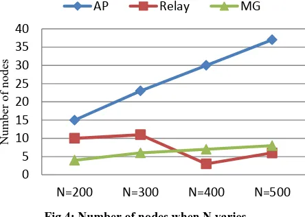
[image:4.595.342.514.517.706.2]Fig.3 shows that the optimal number of APs increases when the number of DPs increases while this has a negligible effect on the relay and the gateways number. This shows that we need more APs to cover all the DPs. The load balancing function is also maximized as it is mentioned in Table 3.
[image:5.595.61.283.133.291.2]Fig 4: Number of nodes when N varies Table 3. Cheapest solutions when N varies
N
Cost
Coverage Load Balancing
APs Relays MGs
200 15 10 4 2986 25
300 23 11 6 6085 30
400 30 3 7 8096 32
500 37 6 8 12771 54
By varying the number of CSs, we observe (in Table 4 and Fig. 4) that the number of relays and gateways increases when the number of CSs increases. This is caused by the need of connecting the network and providing more bandwidth respectively.
We also studied the effect of changing Ti on deployment cost
showed in Fig. 5 and we report in Table 5 the values of the tree objective functions.
When Ti increases, we see the number of APs increases highly
to satisfy this service demand to cover more clients. However, it result a low fairness on links so the throughput decreases.
Table 4. Cheapest solutions when S varies
S
Cost
Coverage Load Balancing
APs Relays MGs
36 17 0 4 2096 28
49 16 6 4 2671 32
64 15 10 4 2986 45
[image:5.595.318.537.300.475.2]100 16 17 9 4219 54
Fig 5: Number of nodes when S varies
[image:5.595.53.281.313.466.2]Fig6: Number of nodes when Tivaries
Table 5. Cheapest solutions when Ti varies
Ti
Cost
Coverage Load Balancing
APs Relays MGs
1 9 12 5 2587 54
2 15 10 4 2986 54
3 25 10 6 4103 45
4 34 3 7 4447 38
5 42 3 8 5324 36
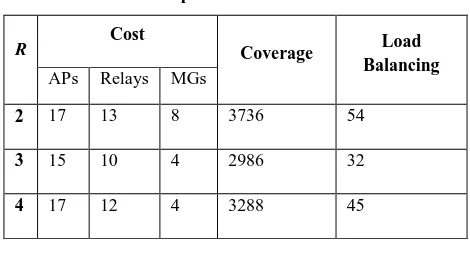
Finally, an optimal number of radio interfaces permits the maximization of throughput and the demand satisfaction with minimum number of nodes. Fig. 6 and Table 6 show that when R = 2, the coverage and the throughput (Load Balancing function) are maximized. While the cost is minimized when R= 3.
0 5 10 15 20 25 30 35 40
N=200 N=300 N=400 N=500
Nu
m
b
er
o
f
n
o
d
es
AP Relay MG
0 5 10 15 20 25 30 35
S=36 S=49 S=64 S=100 S=144
N
u
mb
er
o
f
n
o
d
es
AP relay MG
0 5 10 15 20 25 30 35 40 45
0 2 4 6
N
u
m
b
er
o
f n
o
d
es
Traffic Demand Ti (Mb/s)
[image:5.595.312.544.527.699.2]Fig 6: Number of nodes when R varies Table 6. Cheapest solutions when R varies
R Cost Coverage Load
Balancing
APs Relays MGs
2 17 13 8 3736 54
3 15 10 4 2986 32
4 17 12 4 3288 45
6.
CONCLUSION
In this paper, we proposed a new model and algorithm for wireless mesh networks planning by optimizing new objective functions subject to additional constraints to take into account interference, robustness and load balancing. The use of the MOPSO method to resolve our model provides very interesting results and lets the network planner decide which solution responds to his requirements. Additionally, we studied the effect of varying the key parameters on the cost and the performance of the WMN.
As further research topic, we intend to propose new algorithm for the channel assignment optimization. This will provide a complete solution for WMNs planning.
7.
REFERENCES
[1] I. F. Akyildiz, X. Wang, and W. Wang, "Wireless mesh networks: a survey", Computer Networks and ISDN Systems., Vol. 47, No.4, 2005, pp.445-487.
[2] S. Biswas and R. Morris, “ExOR: opportunistic
multi-hop routing for wireless networks” ACM SIGCOMM Computer Communication Review, Vol. 35, No.4, 2005, pp. 133-144.
[3] P. Gupta, P. R. Kumar, “The capacity of wireless
networks”, IEEE Transactions on Information Theory, Vol. 46, pp. 388–404, 2000.
[4] S. Narayanaswamy, V. Kawadia, R. S. Sreenivas, and P. R. Kumar, “The COMPOW protocol for power control in ad hoc networks: Theory, architecture, algorithm, implementation, and experimentation,” European Wireless Conference, 2002.
[5] M. Burkhart, P. von Rickenbach, R. Wattenhofer, and A. Zollinger, “Does topology control reduce interference?” in proc. of the 5th ACM international symposium on Mobile ad hoc networking and computing. New York, USA: ACM , 2004, pp. 9–19.
[6] G. Brar, D. M. Blough, and P. Santi, “Computationally
efficient scheduling with the physical interference model for throughput improvement in wireless mesh networks,” in MobiCom ’06: Proc. 12th annual international conference on Mobile computing and networking. New York, NY, USA: ACM, 2006, pp. 2–13.
[7] A. Subramanian, H. Gupta, and S. Das, “Minimum
interference channel assignment in multi-radio wireless mesh networks”, 4th Annual IEEE Communications Society Conference, 2007, pp. 481–490.
[8] S. Nahle and N. Malouch, “Placement algorithms for WiMAX Mesh Network”, Next Generation Teletraffic and Wired/Wireless Advanced Networking Lecture Notes in Computer Science, Vol. 5174, 2008, pp. 37-48.
[9] F. Martignon and S.Paris and A.Capone, “Optimal Node
Placement in Distributed Wireless Security Architectures”, Proc. of the 10th international IFIP TC 6 conference on Networking in Spain, Vol. 1 , 2011, pp. 319-330.
[10] F. Xhafa, C. Sanchez, L. Barolli and E. Spaho, “Evaluation of genetic algorithms for mesh router nodes placement in wireless mesh networks”, Journal of Ambient Intelligence and Humanized Computing, Vol. 1, No. 4, 2010, pp.271–282.
[11] V. Targon, B. Sans, and A. Capone, “The joint gateway
placement and spatial reuse problem in wireless mesh networks” The International Journal of Computer and Telecommunications Networking, Vol. 54, No.2, 2010, pp. 231-240.
[12] P.Zhou, X.Wang, B.S.Manoj and R.Rao, “On Optimizing
Gateway Placement for Throughput in WirelessMesh Networks”, Journal of Mobile Networks and Applications, Vol. 13, No.2, 2010, pp. 198 - 211.
[13] Y. Drabu and H. Peyravi, “Planning with Joint
Clustering in Multi-hop Wireless Mesh and Sensor Networks”, The Tenth International Conference on Networks, 2011, pp. 309 - 316.
[14] A. Beljadid, A. Hafid, M. Gendreau, “Optimal Design of
Broadband Wireless Mesh Networks”, IEEE CLOBECOM, 2007, pp. 4840 – 4845.
[15] E. Amaldi, A. Capone, M. Cesana, I. Filippini and F. Malucelli, “Optimization models and methods for planning wireless mesh networks”, The International Journal of Computer and Telecommunications Networking, Vol. 52, No.11, 2008, pp. 2159 - 2171.
[16] D. Benyamina, A. Hafid, and M. Gendreau, “A
multi-objective optimization model for planning robust and least interfered wireless mesh networks,”, IEEE GLOBECOM 2008, Vol.2, pp. 5307-5312.
[17] D. Benyamina, A. Hafid and M. Gendreau,”Throughput Gateways-Congestion Trade-Off in Designing Multi-Radio Wireless Networks”, Journal Mobile Networks and Applications Vol. 16, No. 1, 2011, pp. 109-121. 0
2 4 6 8 10 12 14 16 18
R=2 R=3 R=4
Nu
m
b
er
o
f
n
o
d
es
[image:6.595.49.284.268.400.2][18] Carlo R. Raquel , Prospero C. Naval, “An effective use
of crowding distance in multiobjective particle swarm optimization”, In Proc. of Genetic and and Evolutionary Conference, 2005,257–64,.
[19] J. Kennedy and R. C. Eberhart, “Particle Swarm Optimization”, In Proc. of the IEEE International
Conference on Neural Networks.1995, Vol. 4, pp. 1942-1948.
[20] J. Robinson and E. W. Knightly, “A performance Study