Controlling Remote Peripherals using Data Present in
the Cloud
Rahul R Upadhyay
BTech(Mechanical) BBDNITM, INDIA
Rajeev Rao
BTech(Instrumentation) JSS NOIDA,INDIAABSTRACT
In this paper we have developed a novel method to control peripherals kept at remote locations using information present in the cloud or DNS host server. Controlling peripherals via conventional methods like DTMF module requires human intervention at every step (viz pressing keypad etc) and only one system can be operated at one instance. Here we will describe how code already present in the cloud can be fetched by the system(s) and operated upon without continuous human intervention. In the simplest case our method can be described in terms of three nodes (computers). The first node is basically a computer or device that sends data to the second node which is basically a webhost. Data sent via the first node is stored in the host data bank and is universally accessible. Thus this data or set of code becomes “data in cloud”. Third node is a remote computer connected to the peripheral to be controlled via a special module(called Node.3.Module). This computer has a software that acquires the data on cloud (or webhost data bank) and produces discrete signals which instruct the module laced with a microcontroller to perform corresponding tasks on the peripheral.
General Terms
Remote controlling of peripherals. Cloud Data.
Keywords
Cloud Data, DTMF(MT8870PI), Atmega16, ULN 2803, PHP, Visual Basic Portable.
1.
INTRODUCTION
As already stated that our method can be described in terms of three nodes(computer) in the simplest of the case. First node is the one via which data would be transmitted using specific software to the second node which is basically a webhost on which a PHP script acquires the data and puts it in a text file which is also present on the same host. This data present in the text file is now universally accessible and acts as “data in the cloud”. Now the third node is basically a peripheral-specific-module(laced with a DTMF IC and Atmega16) that connects a peripheral to a computer via headset (not via serial port/parallel port etc which are becoming obsolete and less common).The third node(remote computer) has a piece of software which acquires the data in the cloud or on the host and produces corresponding DTMF tones which go in the module via the headset and the module takes corresponding action as it is programmed to control the peripheral. Using this novel method several peripherals can be remotely controlled via a set of code that is deployed in the cloud. Node1 can be called DATA TRANSMITTAL NODE. Node2
can be called WEBHOST NODE and Node3. can be called DATA RECEIVING NODE.
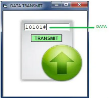
Though this methodology can be altered and applied in numerous ways but for explanation purpose we would be using a very simple approach. Data in the data transmittal stage is entered in the transmittal software as a five digit code followed by a hash code. Here each digit is either a 0 or 1 and all digits have equal significance. When this data is sent to the php script on the remote host, then the script simply puts this data in the main.txt file. Data retrieval software that is present on remote computer (connected to the peripheral) performs a timer cycle and keeps checking the changes in the main.txt file and on observing any change of content in the file it acquires the present content. Now the same software analyses the data and puts each digit of the five digit code in separate variables. Now depending on the combination of the data (0 or 1) in the variables, specific DTMF signals are generated and fed to the MT8870PI IC on the Node3 module via a headphone. The corresponding output of MT8870PI IC is fed to Atmega 16 microntroller which is preprogrammed depending on the problem statement and a series of relays are connected to it to be controlled which basically are nothing but remote peripherals in question.
Fig 1: Five Digit code followed by hash.
2.
DESCRIPTION OF DATA
TRANSMITTAL NODE
Fig 2: Transmitting Software.
2.1
Mode of data entry
Data in the data transmittal stage is entered in the transmittal software as a five digit code followed by a hash code. Here each digit is either a 0 or 1 and all digits have equal significance as already mentioned.
2.2
Html and Vb Code
Here the HTML page namely
http://friendship.myartsonline.com/data.html accepts the five digit data in “Editbox1” and on submission sends it to http://friendship.myartsonline.com/trim.php.
In VB6 portable a “Microsoft Internet Control” component is used to create a mini web browser that opens up the above mentioned HTML page via “Navigate” object.
3.
WEBHOST NODE
Webhost node is the second node or stage of peripheral controlling via cloud. In this the 1’s and 0’s sent by the the data transmittal graphical user interface program is accepted by the PHP script. This script uses file handling functions in its library to save the data in a text file which is also deployed on the same host directory.
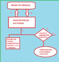
3.1 Diagrammatic Description (figure2)
It can clearly be seen by the flow chart, the functioning of the php script .To ascertain that the data has been sent to the script via data.html and no other illegitimate source, we had put a condition that the script would perform the file handling process only when the submit button on the data.html page is found to be clicked.
If this criteria is fulfilled then a pointer variable is created that points towards “main.txt” file which is the location where the data sent from data transmittal software is to be stored for referencing by Node3 systems for taking suitable actions. The php script namely “trim.php” can also be modified to do password verification also so as to provide entry to only legible parties. But for sake of simplicity we have not done any password verification process here.
3.2
PHP Script
#A: Condition to test if Button1 i.e the Submit button was clicked or not.
#B:”main.txt” is wrapped to variable $myvariable
#C: Using the fopen function the file “main.txt” is opened in “w” mode or “write-mode”.
#D:fwrite function is used to write the data stored in variable $stringdata to main.txt pointed be $fh pointer.
#E: $fh pointer function is closed.
The above notes describe the functioning of the PHP code.
4.
DATA RETRIEVAL NODE
Data Retrieval node is the most complex, elaborate and essential part of this entire methodogy. In this node a visual basic software is present on remote computer which is programmed to see the variations in the main.txt file within every 50 microseconds. On noticing any change in the content ,the software immediately copies the data in the text file and stores each digit in separate variables. Depending upon the variable combination that is pre programmed, corresponding DTMF tones are generated which are fed to Node3.Module
4.1
Data Retrieval From Cloud
Data in the cloud or the content from “main.txt” which is stored on the remote host is fetched by visual basic software which basically runs a timer code and checks for changes in main.txt. It acquires the data and produces certain DTMF tones depending on the data recieved. This DTMF tone(later explained) is then fed to Node3.module.
4.1.1 Description of software for data
retrieval from cloud.
In this paper we aim at showing the method of fetching data from cloud and controlling a peripheral which can be anything but in this case it is a group of four electromagnetic relays.
Following are the essential features of the peripheral-specific software (in this case; electromagnetic relays):
1. For the sake of explanation of our methodology we have created a simple VB program in which “Private Sub Timer1_Timer()” function calls “Private Function add()” within every 500 micro seconds.
2. “Private Function add()” creates six variables
“contentfile, contentfile1 ,contentfile2.”. It then calls “Inet.OpenURL” function to fetch the content of
“main.txt” viz :
contentfile=Inet1.OpenURL("http://friendship.myart sonline.com/main.txt")
3. Now the content in variable contentfile i.e. the five digit number followed by hash code is de-concatenated and all the five digits are placed in five different variables.
contentfile1 = Mid(contentfile, 1, 1) contentfile2 = Mid(contentfile, 2, 1) contentfile3 = Mid(contentfile, 3, 1) contentfile4 = Mid(contentfile, 4, 1) contentfile5 = Mid(contentfile, 5, 1) contentfile6 = Mid(contentfile, 6, 1)
4. We have programmed the software to show a set of images whenever a new content or data(five digit code) is received.
If contentfile1 = "1" Then Picture1p.Visible = True Else
Picture1p.Visible = False End If
Thus if variable in contentfile1 is “1” then a picture appears in the GUI. Similarly other image files are shown when the value of remaining four variables becomes “1”.
5. Now we take an arbitrary approach and program the software to produce following DTMF tones depending on content in variables (any other approach can also be taken depending on results needed)
contentfile1 = "1" | DTMF tone for 1 contentfile2 = "1" | DTMF tone for 2 contentfile3 = "1" | DTMF tone for 3 contentfile4 = "1" | DTMF tone for 4
These are the tones that go inside the Node3.module via headphone jacks.
Just above the function module add() following function declaration has to be added to run “.wav” files of DTMF tones
.“Private Declare Function sndPlaySound Lib "winmm.dll" Alias "sndPlaySoundA" (ByVal lpszSoundName As String, ByVal uFlags As Long) As Long”
[image:4.595.318.571.121.383.2]The data retrieval process can be described by flowchart mentioned in Figure 3. Figure 4 is the snapshot of the VB GUI for fetching data from cloud whose development code has already been mentioned.
Fig 4:Query Paradigm.
[image:4.595.315.544.509.655.2]4.2
DTMF Signals (Brief Description)
Fig 6: Frequency Groups of DTMF Signals.
DTMF which stands for Dual tone multi frequency signal. These signals are composed of two tones of different frequency combinations. One tone belongs to higher frequency belt and the other to the low frequency belt. A dtmf signal is the algebraic sum of two different audio frequencies and can be represented by following expression:
F(t) = M sin(2*П*a1*t) + N sin(2*П*a2*t) + ... >(1)
[1] Where a1 and a2 are two different audio frequencies and and M,N are the amplitudes of tone waves.
[2] The amplitudes of the two sine waves should be such that
(0.7 < (A/B) < 0.9)V
4.3
Node3 Module
4.3.1 DTMF Tone Receiver (MT8870PI)
Node3 module for controlling peripherals we have used MT8870PI DTMF receiver which is basically a band pass filter which uses switched capacitor technique for bifurcating the two separate frequencies by which the DTMF signal is composed of. Now both these separate signals are fed into a Digital Detector Algorithm. The signal is then routed to Code Converter and latch which produces four different outputs on four different pins and these are the outputs that are actually fed to microcontroller in following stages. Ref figure 5 for basic setup circuit of MT8870 set of DTMF ICs.
In section 4.1 it is mentioned that if the value in contentfile1, contentfile2, contentfile3 and contentfile4 is “1” then DTMF tones of “1”, “2”, “3”, “4” would be generated respectively.
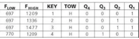
Table 1. Output Signals on MT8870PI
The above chart describes the values on output pins of decoder ic when different DTMF tones corresponding to
[image:5.595.321.544.137.310.2]receives “1” then DTMF tone corresponding to “4” would be produced whose lower frequency is 770 and higher frequency is 1209. Under this tone the output of decoder IC would be such that the Q3 pin would be high and Q1,Q2 as well as Q4 pin would go on low voltage.
Fig 7: Basic Circuit of CM8870..
4.3.2 Microcontroller Setup (Atmega16)
The Atmega16 is a medium-power 8-bit microcontroller. Atmega 16 microcontrollers have enhanced AVR RISC architecture and are CMOS integrated circuits.
It has a 16 kilo byte programmable flash memory that is present on the system and has both read as well as writes capabilities. It has 512 bytes of EEPROM and 1kb of SRAM. It comes with built in 32 general purpose working registers and all these 32 registers are connected to the ALU or arithmetic logic unit directly thus allowing two independent registers to be accessed in one single instruction executed in one clock cycle.
In this module Q1 through Q4 outputs of the DTMF decoder IC are connected to port pins PA0 throughPA3 of ATmega16 microcontroller.
Microcontroller has to programmed such that for it identifies different inputs from DTMF and on the basis of that produces corresponding outputs on PORT D to control the peripherals(in this case relays).
It is already mentioned that Node3 module in our methodology is a peripheral specific module and has to be designed/programmed keeping in view the peripherals requirement. Here we arbitrarily assign different combinations of highs and lows from Q1 to Q4 of decoder IC which acts as input to microcontroller to switch on different relays .Following table describes our approach in this case:
Table 2. Output on PORTD
[image:5.595.318.537.620.705.2] [image:5.595.55.279.671.734.2]4.3.2.1 Microcontroller Program
(Atmega16)
// sensor() is an arbitrary name of a function.
// PORT A is used to take input and PORT D is used for output purpose.// the output of microcontroller is fed to relays via a buffer ic called ULM 2803.
4.3.3 ULN 2803
A ULN2803 is an Integrated Circuit (IC) chip with a High Voltage/High Current Darlington Transistor Array. It allows you to interface TTL signals with higher voltage/current loads. In English, the chip takes low level signals (TLL, CMOS, PMOS, NMOS - which operate at low voltages and low currents) and acts as a relay of sorts itself, switching on or off a higher level signal on the opposite side.
A TTL signal operates from 0-5V, with everything between 0.0 and 0.8V considered "low" or off, and 2.2 to 5.0V being considered "high" or on. The maximum power available on a TTL signal depends on the type, but generally does not exceed 25mW (~5mA @ 5V), so it is not useful for providing power to something like a relay coil. Computers and other electronic devices frequently generate TTL signals. On the output side the ULN2803 is generally rated at 50V/500mA, so it can operate small loads directly.
Here ULN 2803 acts as a buffer IC between microcontroller and relays. We are using electromagnetic relays and thus the switching takes place when current flowing in the coil acts as an electromagnet and attracts the conductor buckle. The biggest disadvantage of electromagnetic relays are that it produces back emf or back electromotive force which may harm the microcontroller thus we put a buffer IC i.e ULN to hinder the path of back current caused by back emf.
[image:6.595.316.538.539.753.2]It has already been mentioned that Node3 module is peripheral specific module and its hardware may wary depending upon the peripheral in question.If we had to control a peripheral which did not produce back emf then ULN was not required.
5.
Diagram of entire methodology.
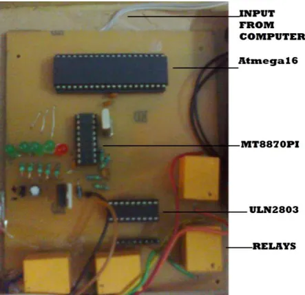
.Figure 8: Node3.module
Figure 9: Schematic of Node 3 module.
6.
CONCLUSION AND DISCUSSION
1. Using this methodology machines and instruments that might be dangerous or hazardous to work around can be controlled from miles away.
2. The signal from Node3 computer does not go to Node3 module via serial port/parallel port which is generally not present in new generation computers and laptops but via a headphone jacks.
3. The biggest disadvantage of this approach of peripheral controlling is the dependency on internet speed. If high net speed is available then this methodology is very useful.
4. ULN 2803 can be replaced by cheaper buffer IC’s w without any significant change in output in terms of speed.
4. UNIX servers have shown better performance as webhosts than windows servers.
7.
ACKNOWLEDGEMENTS
Rahul R Upadhyay would like to thanks professor Veeranga Iyer and also his parents and teachers for constant support and help.Rajeev Rao would like to thank Professor Vishwanathan Shridhar.
8. REFERENCES
[1] Yong-tao ZHOU, Xiao-hu CHEN, Xu-ping WANG, hun jiang YAO, 2008”: Design of Equipment remote monitoring System Based on Embedded Web”, IEEE, pp 73-78.
[2] Ali Ziya Alkar, Mehmat Atif Karaca, 2009”, An Internet Based Interactive Embedded Data- Acquisition System for Real-Time Applications”, IEEE, Vol .58.No.3, pp 522- 529.
[3] Mo Guan, Wei, Ying Bao, 2008 ” A Monitoring System Based on Embedded Internet Technology for Embedded Devices”, IEEE ,Vol. pp.5-8.
[4] Paper on remote process control and monitoring using matlab By Sysel M. Pomykacz, Tomas Bata University. [5] Remote access real time laboratory: Process monitoring