Modern College of ACS, Pune-5. Maharashtra, India.
Shivaji University, Kolhapur. Maharashtra, India.
Shivaji University Kolhapur. Maharashtra, India.
ABSTRACT
This paper describes FPGA implementation of a Fuzzy Logic Controller (FLC) using VHDL for temperature control (FTC). The system is built up with major modules namely fuzzification, inference, implication and defuzzification. The VHDL code is downloaded into FPGA board of SPARTAN- 3 XC3S400 in PQ208 pin package. The FTC is also modeled in C and matlab. Output of FTC in VHDL, C and Matlab are compared for different input conditions for verifying the functionality of the FTC chip,
Keywords
FPGA, FLC, FTC, Fuzzification, implication, defuzzification..
1.
INTRODUCTION
For many years, fuzzy logic has been an attractive technology for designers of industrial, consumer and automotive products. However, achieving the right balance between cost and performance has not always been easy. Dedicated fuzzy processor chips can meet the most demanding performance needs. VHDL-based logic synthesis is an efficient method for designing complex hardware.
This paper describes FPGA realization of a Fuzzy Logic Controller (FLC) using VHDL for temperature control (FTC). A fuzzy system improves the relative performance of a temperature control process with respect to the conventional scheme [1]. It compensates non-linear errors, accelerates the response and reduces the steady-state error and maintains temperature constant at the desired value regardless of changes in the load or environment.
FLC structure with closed loop control system and realization of small rules for industrial temperature control system demonstrated that the fuzzy logic control is much more capable than the current temperature controllers. Four control schemes namely PID, fuzzy logic control(FLC), FLC using genetic algorithms (FLC-GA) and Neuro-Fuzzy control (NFC) presented by Thyagarajan for regulating the temperature of the Air Heat Plant highlighted superiority of FLC over PID, FLC-GA FLC and NFC schemes. All these schemes are evaluated with respect to set-point tracking using performance indices [2] [3].
In this paper, the control system is implemented using VHDL, aiming for FPGA implementation. There are several advantages for this approach. Field programmable Gate Array (FPGA) is used as hardware platform, because FPGA allows very high logic capacity (the amount of digital logic that can be mapped into a single FPD [4] [5]. FPGAs offer more flexibility than ASICs, as when a design is not needed any
more; the chip can be reprogrammed for a new hardware. Thus, the FPGA based systems are flexible and can be reprogrammed number of times [6]. Fuzzy algorithms can be executed on low-cost conventional microcontrollers, but as these have architectures that were not designed to handle fuzzy logic, the software overhead often makes the performance inadequate. Dedicated fuzzy processor chips can meet the most demanding performance needs.
2. Development of the FTC Algorithm
Here the algorithm is developed for controlling the temperature. The models of the controller based on fuzzy rules are known as, the Fuzzification module, Inference module, Implication module, and Defuzzification module [7] [8]. All the relevant and crucial parameters are explained and illustrated, including the set of fuzzy rules applicable. The fuzzy model has been coded in C also presented in this paper.
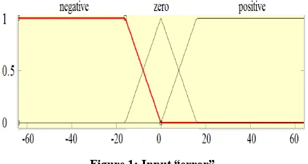
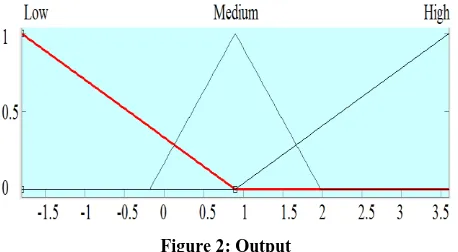
[image:1.595.318.541.550.669.2]Difference between set temp and current temp (Error)is taken as input in the model. Input “Error” consists of two trapezoidal membership functions (negative and positive) and one triangular membership functions (zero) over a range from -64 to 64. Figure 1 illustrates the fuzzy variables. Based on these, the fuzzy logic model determines the amplitude of the voltage signal that is necessary to be sent to the heater in order to maintain a constant temperature in the industrial process. This is provided by “Output” (output signal) from the model, with a range of [-1.8 to 3.6]. The “Output” signal has 3 triangular membership functions (low, medium and high) spaced over this range as shown in figure 2.
Figure 2: Output
[image:2.595.318.543.69.254.2]Three fuzzy rules (IF/THEN) used in the model are shown in figure 3. The connective OR is maximum operation interpretation. While the connective AND is given a minimum interpretation. The output is produced based on various combinations of the fuzzy inputs.
[image:2.595.55.284.73.199.2]Figure 3: Fuzzy IF - THEN rules
Figure 4: Matlab rule view
Fig. 4 is a Matlab generated input output relation by firing the rules. (For specific value, input = 4.85 and output=1.53). And fig 5 shows the matlab generated plot that shows the surface of the fuzzy rules used in the model [9]. It is important to note that the surface changes in a gradual and smooth manner with fuzzy variable “error”. This smooth change in the surface indicates that the rules as a whole are consistent and hence an accurate output might be produced by the system. In addition, both inputs and output range can be normalized so that system becomes adaptable to various input/output parameters, through the use of appropriate simple conversion circuits. Hence, the model can be used for different processes with simple change in algorithm.
Figure 5: Matlab surface view
3. Modeling of the FTC in C
Here the FTC algorithm developed in C is used as a reference and verification tool for the VHD model. For developing VHDL algorithm input “error” is normalized to the range from 0 to 128.
The FTC has been divided into four modules according to function, i.e. Fuzzification, Inference, Implication, and Defuzzification. It accepts input “error”, and produces a crisp output value “Output”, using rules as shown below.
R[1] = E[n]
R[2] = E[z]
R[3] = E[p]
Where n, z and p refers to membership functions negative, zero and positive for error . The C statement, R[1] = E[n], corresponds to the rule 1: If input (error) is negative then output is R1.
3.1 Fuzzification module
[image:2.595.55.281.351.535.2] [image:2.595.318.541.587.749.2]Figure 7: Membership function of “error”
3.2 Inference module
[image:3.595.56.280.138.266.2]In this module, appropriate rules are fired according to fuzzy variables. Only two fuzzy variables are activated at any given time. Hence each fuzzy variable results in firing two rules. Here the universe of discourse is divided into 2 regions where each region containing only two fuzzy variables
Figure 8: Inference
Here in figure 8, error = 4 with membership functions zero (E[z] = 0.75) and positive (E[p] = 0.25). Hence according to IF–THEN rules of the system (figure 4), rules 2 and 3 are selected
.
[image:3.595.54.283.375.529.2]3.3 Functional and timing simulation
Figure 9: set temp
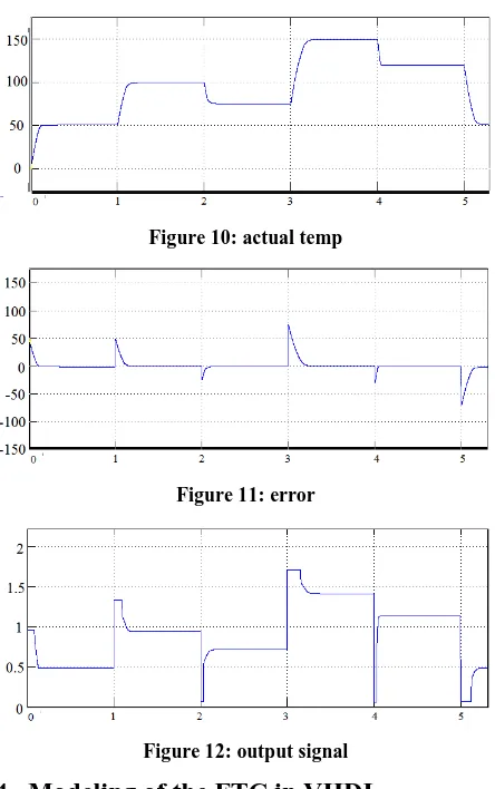
Figure 10: actual temp
Figure 11: error
Figure 12: output signal
4. Modeling of the FTC in VHDL
FTC Algorithm is developed in VHDL with two input variables (set temp and actual temp) and one output variable. The difference between set temp and actual temp is error, after fuzzification error is divided in to three Fuzzy sets, as negative, zero and positive. Based on these Fuzzy sets 3 rules are fired and output is produced after Defuzzification. Upon successful completion of the VHDL coding functional simulation is performed to verify the correct functionality and to determine the deviation or tolerance parameters of the FTC using VHDL test bench.
[image:3.595.57.279.631.730.2]Figure 13: VHDL test bench output.
For verifying the functionality of the VHDL code, output of VHDL, C, and Matlab are compared for different input conditions, as shown in table below. For VHDL coding
the input is normalized to the range of 0 t0 128.
5. FPGA Implementation.
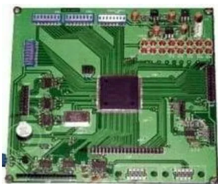
[image:4.595.78.519.304.405.2]The generated VHDL code of the FTC has been downloaded into FPGA (SPARTAN- 3 XC3S400 in PQ208 pin package). Two inputs are connected to I/O pins through A to D converter, as shown in figure 14. The photograph of FPGA development board is shown in figure 15. Note that the FPGA board contain a built-in 16 digital output LED’s, 32 Input switches, 72 Free I/Os, 2 Serial interface, Communication Interface UART (RS-232) and is Configuration through Flash PROM and JTAG Port
Figure 15: FPGA Development board (SPARTAN- 3 XC3S400 in PQ208 pin package.)
[image:4.595.315.535.453.639.2]The I/O pins of FPGA board are connected to input 1, input 2 and output for verifying the correct functionality of the FTC chip for FPGA implementation
.
Table 1: Inputs and the corresponding output in hexform at the various instances
Input to matlab and C
normalized Input to VHDL
Matlab output
C output VHDL output De- normalized VHDL output
-4 8 0.339 3.4 03 0.375
-2 16 0.58 0.58 05 0.625
0 24 0.9 0.9 08 1
[image:4.595.57.273.599.737.2]7. Conclusions
The efficient design of the Fuzzy Logic controller according to the desired specifications using VHDL and its implementation on FPGA is useful for realizing a prototype of the Fuzzy Logic controller, applicable in real time systems. A fuzzy logic temperature controller has been designed for controlling the temperature. After de normalization VHDL output is used to control the current for maintaining the temperature at desired value.
8. References:
[1] Ayala, I.L., and Solis, I.J. 1991. IEEE Transactions on Industry Applications. Volume: 27 , Issue: 1, pp:108 – 111
[21] Zhiqiang, Gao, Trautzsch, T.A., and Dawson, J.G., A stable self-tuning fuzzy logic control system for industrial temperature regulation, IEEE Industry Applications Conference, Vol.2, 2000, pp. 1232 – 1240.
revised Sep. 17, 2007.
[5] Brown, S.D., Francis, R.J., Rose, J., and Vranesic, Z.G., Field-Programmable Gate Arrays, Kluwer Academic Publishers,1996
[6] K.T. Tho, K.H. Yeow, F. Mohd-Yasin, M.S. Sulaiman, and M.I. Reaz, VHDL Modeling of Boolean Function Classification Schemes for Lossless Data Compression, WSEAS Transactions on Computers, Vol.3, No.2, 2004, pp. 365-368.
[7] K. Tanaka (Translated by T. Niimura), 1997, “An Introduction to Fuzzy Logic for Practical Applications”, Springer- Verlag, New York, Ch. 4, 5, pp. 86-136.
[8] L. A. Zadeh, 1965, “Fuzzy sets,” Information and Control, vol. 8, pp. 338–353.
[9] Mathworks Inc. MATLAB User Manual for MATLAB and Fuzzy Logic Toolbox.