Current Mode Programmable Analog Modules using Low
voltage Digitally Controlled CMOS CCII
Iqbal A. Khan
Department of Electrical Engineering,
Faculty of Engineering and Islamic Architecture,
Umm Al Qura University, Makkah, Saudi Arabia
Ahmed M. Nahhas
Department of Electrical Engineering,
Faculty of Engineering and Islamic Architecture,
Umm Al Qura University, Makkah, Saudi Arabia
ABSTRACT
The current mode programmable analog modules are realized using digitally controlled low voltage CMOS current conveyors. These programmable modules include current mode amplifiers, integrators, differentiators, first order multifunctional filter and second order multifunctional filters. The realized current mode programmable analog modules can provide digital control to the parameters through an n-bit control word with high resolution capability and reconfigurability. These programmable analog modules are suitable for realizing current mode field programmable analog array. The realized programmable analog modules are designed and verified using PSPICE and the results thus obtained justify the theory.
General Terms
Digitally programmable analog modules.
Keywords
Current conveyors, current mode amplifiers, filters.
1.
INTRODUCTION
Recently, the introduction of digital control to the current conveyor (CCII) has boosted its functional capability and versatility in addition to its higher signal bandwidth, greater linearity and large signal bandwidth [1-14]. This digital control has eased the on chip control of continuous time systems with high resolution capability and reconfigurability [1-8].
This paper basically deals with the realization of reconfigurable current mode programmable analog modules (CMPAMs) using digitally controlled low voltage CMOS CCII [1-4], [6-8]. The realized CMPAMs include the current mode amplifiers, integrators, differentiators, first order and second order multifunctional filters using Low voltage digitally programmable CMOS CCII (DPCCII). All the realized CMPAMs provide digitally programmable module parameters through an n-bit control word. These CMPAMs can be used as a programmable module of a field programmable analog array (FPAA) [15], [16]. To verify the theory, the realized CMPAMs are designed and verified using PSPICE and the results thus obtained justify the theory.
2.
THE CMOS DPCCII
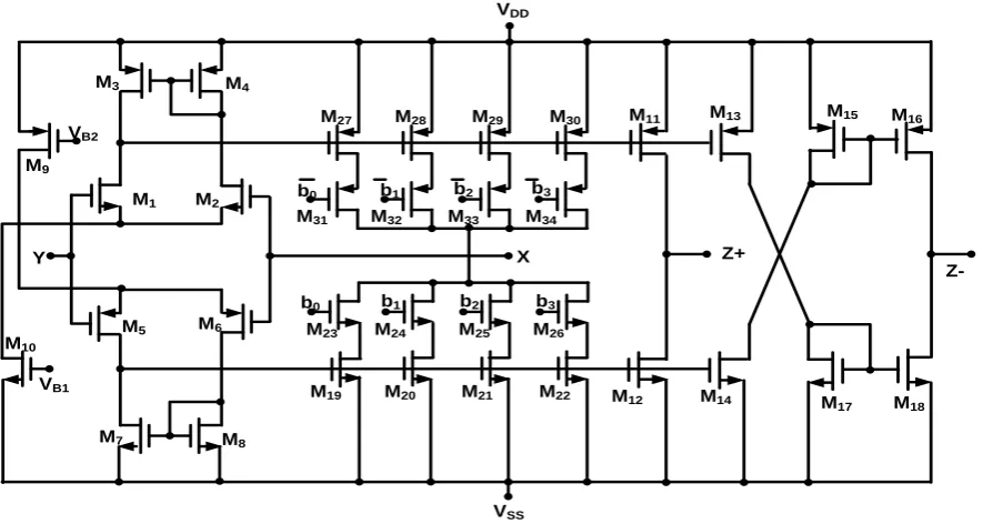
The digitally programmable CCII (DPCCII) symbol is shown in “Figure 1(a)” and its CMOS implementation with 4-bit
control word is shown in “Figure 1(b)” [4], [8]. The current summing network (CSN) is included at port-X. The transfer matrix can be expressed as
Z X Y
m Z
X Y
V
I
V
N
I
V
I
0
0
0
0
0
0
0
(1)Thus the port voltages and currents for DPCCII can be expressed as
X m Z
Y X
Y
I
N
I
V
V
I
,
,
0
(2)
In equation (2) α is the voltage transfer gain from terminal-Y to terminal-X and β is the current transfer gain from X to Z. Both the voltage gain (α) and the current gain (β) are ideally unity. N is an n-bit digital control word, the plus sign(+) is for IZ+ and minus sign(-) is for IZ-. The power integer m = 1 for
current summing network (CSN) at port-Z and m = -1 for current summing network (CSN) at port-X of the DPCCII [1], [4-8]. The additional number of Z+ or Z- outputs may be added as per requirement just by connecting in parallel a set of PMOS and NMOS for each output as shown in “Figure 1(b)”.
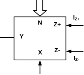
Y
X Z-Z+
N IZ+
I
[image:1.595.360.497.590.712.2]Y
VDD
VSS VB2
VB1
M1 M2
M3 M4
M6 M5
M7 M8
M9
M10
X b0 b1 b2 b3
b0 b1 b2 b3 M31 M32 M33 M34
M19 M20 M21 M22 M23 M24 M25 M26
Z+ M11
Z-M12
M13
M14
M15 M16
M17 M18 M27 M28 M29 M30
Fig 1(b): The CMOS implementation of a 4-bit DPCCII with CSN at port X
3.
THE CMPAM CIRCUITS
Three current mode programmable analog module circuits are given, viz., CMPAM-1, CMPAM-2, and CMPAM-3.
3.1
CMPAM-1: Digitally Progrmmable
Current Amplifiers
The CMPAM-1 is the digitally programmable current amplifier using CMOS DPCCII is shown in “Figure 2”. The circuit uses one DPCCII along with grounded resistors R1 and
R2.
Y
X
Z-Z+ N
IO+
I
O-Ii
R1
R2
Fig 2:CMPAM-1: Digitally Progrmmable Current Amplifiers
The routine analysis yields its non-inverting and inverting current gains respectively G+ and G- as follows.
2 1 R R N Ii
I
G O
m
and
2 1 R R N Ii
I
G O
m
(3)
From equation (3) it is clear that the current gains can be set directly or inversely proportional to n-bit digital control word
N by choosing the DPCCII with m = +1 or -1, respectively as described in Section-II. It is to be noted that both the resistors can be set equal to minimize the component spread which is desirable for IC implementation. The non-ideal gains α and β may slightly affect the gain which can be adjusted through resistors ratio R2 /R1.
It is also to be noted that by replacing R1 with a capacitor in
“Figure 2”, the CMPAM-1 results a digitally programmable integrator with inverting and non-inverting outputs. Similarly, by replacing R2 with a capacitor the CMPAM-1results a
digitally programmable differentiator with inverting and non-inverting outputs.
3.2
CMPAM-2: Digitally Programmable
Current Mode First-Order
Multifunctional Filters
The CMPAM-2 is the digitally programmable current mode first order multifunctional filter using CMOS DPCCII is shown in “Figure 3” [7]. The circuit uses one CCII and one DPCCII, each one with three outputs along with grounded R and C components. The DPCCII uses the CSN at port-X as shown in “Figure 1(b)”. The routine analysis yields its current transfer functions respectively for low pass, high pass and all pass filters as
RC
N
s
RC
N
I
I
IN LP
4(a)RC
N
s
s
I
I
IN HP
[image:2.595.81.524.74.310.2] [image:2.595.89.240.469.606.2]RC
N
s
RC
N
s
I
I
IN AP
4(c) Y X Z-Z+ N Z+I
AP Y X Z-Z+Z-I
LPI
HPI
IN R C1
2
Fig 3: The CMPAM-2: Digitally Programmable Current Mode First order Multifunctional filter
The pole frequency (ω0) and the phase angle (ϕ) for the APF
can be expressed as follows.
)
(
tan
2
1 0N
RC
RC
N
(5)From equation (4) it is evident that the pole frequency ω0 is
directly proportional to the digital control word N. Also the phase can be controlled through N at any constant pole-ω0.
The control through external digital control word N, facilitate the on chip system control. Thus the multifunctional filter of “Figure 2” can be used as a programmable module of a field programmable analog array (FPAA)[15].
Taking the non-idealities of CCIIs into account as given in equation((2), with α1 and β1 for CCII-1 and α2 and β2 for
CCII-2, the ideal transfer functions given in equation (4) yield the non-ideal transfer functions as follows.
RC
N
s
RC
N
I
I
IN LP 2 2 1 1 2 2 1 1
6(a)RC
N
s
s
I
I
IN HP 2 2 1 1
6(b)RC
N
s
RC
N
s
I
I
IN AP 2 2 1 1 2 2 1 1
6(c) Also the equation (5) reduces to
)
(
tan
2
1 1 2 2 1 2 2 1 1 0N
RC
RC
N
(7)The equations (6) and (7) show that with α1= α2 and β1= β2,
the pole-frequency for first order multifunctional filter and the phase angle ϕ for the all pass section are unaffected due to non-idealities.
3.3
CMPAM-3: Digitally Programmable
Current Mode Second-Order
Multifunctional Filters
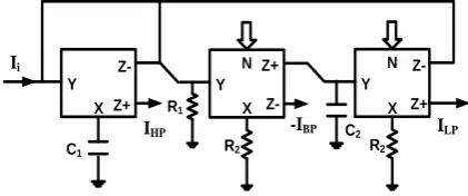
The CMPAM-3 is the digitally programmable current mode second order multifunctional filter using low voltage digitally controlled CMOS DPCCII with m=1, is shown in “Figure 4”. The circuit uses three DPCCII, each one with two outputs along with grounded R and C elements.
[image:3.595.327.538.447.535.2]Y X Z-Z+ Ii Y X Z-Z+ N R1 R2 Y X Z-Z+ N R2 C2 IHP C1 ILP -IBP
Fig 4: The CMPAM-3: Digitally Programmable Current Mode Second order Multifunctional filter The routine analysis yields its current transfers functions respectively for low pass filter (LPF), band pass filter (BPF) and high pass filter (HPF) as follows.
2 1 3 2 2 1 1 2 2
1
C
C
R
R
N
C
R
s
s
s
I
I
IN HP
8(c)By just directly adding IHP and ILP the Band Reject (BR)
output (IBR) response can easily be obtained and the resulting
transfer function can be expressed as follows.
2 1 3 2 2 1 1 2 2 1 3 2 2 2
1
C
C
R
R
N
C
R
s
s
C
C
R
R
N
s
I
I
IN BR
8(d)And by directly adding IHP, IBP and ILP with R1=R2, the
All-Pass output (IAP) response can easily be obtained and the
resulting transfer function can be expressed as follows.
2 1 3 2 2 1 1 2 2 1 3 2 2 1 1 2
1
C
C
R
R
N
C
R
s
s
C
C
R
R
N
C
R
N
s
s
I
I
IN AP
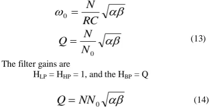
8(e)From equation (4) the filter parameters can be expressed as follows.
The pole frequency
3 2 2 1 0
R
R
C
C
N
9(a) The pole-Q 3 2 2 1 1R
R
C
C
N
R
Q
9(b)If resistance R1 is replaced by an equivalent digitally
programmable resistor (DPR) as shown in “Figure 5”, and
0 1
N
R
R
(10)with R = R2 = R3, and C1 = C2 = C, the pole-ω0 and pole-Q
from equation (5) reduces to
[image:4.595.325.533.601.707.2]Z-X Y R 0 1
N
R
R
N0Fig 5: The digitally programmable resistor (DPR) using CMOS DPCCII with m=1
RC
N
0
0N
N
Q
The filter gains are
HLP = HHP = 1, and the HBP = Q
(11)
From equation (6) it is evident that the pole frequency ω0 is
directly proportional to digital control word N. The pole-Q can be independently controlled through the digital control word NQ. The minimum N0 = 1, and thus maximum Q = N.
However, by selecting the DPCCII with m = -1, for the DPR of “Figure 5”, with R1 = RN0, results the pole-Q as
Q = NN0 (12)
Thus from equation (7), it is obvious that the pole-Q can be independently and directly controlled through the digital control word N0. Now with N0 = 1 the minimum Q = N. The
maximum Q = NN0 and the choice is suited for designing
high-Q filter.
Taking the non-idealities of CCIIs into account as given in equation (2), for the CMPAM-2 of “Figure 4”, with identical α and β for all the CCIIs, the ideal relationship of pole-ω0,
filter gains and pole-Q given in equation(11) and (12) respectively, yields the non-ideal pole-ω0, filter gains and
pole-Q as follows.
RC
N
0
0N
N
Q
The filter gains are
HLP = HHP = 1, and the HBP = Q
(13)
0NN
Q
(14)4.
DESIGN AND VERIFICATION
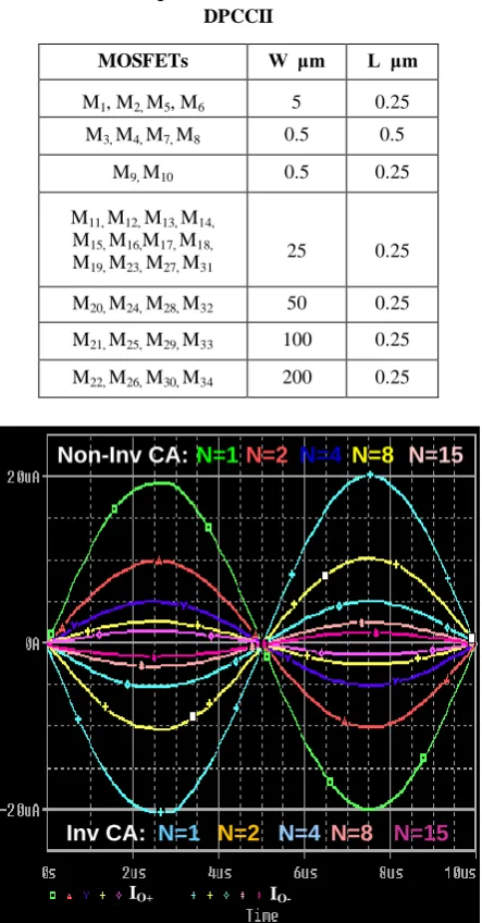
All the realized digitally controlled current mode programmable analog modules of Section-1 were designed and verified by performing PSPICE simulation with supply voltage ± 0.75V using CMOS TSMC 0.25μm technology parameters. The CMOS DPCCII with 4-bit current summing network at port-X (i.e. m = -1) of Fig. 1(b) was used for CMPAM-1 and CMPAM-2. The aspect ratios used are given in the Table 1. The CMPAM-3 was verified using the DPCCII with the CSN at port-Z (i.e. m=1). The CMPAM-1 i.e. the current amplifier was initially designed for a current gain of unity with R1=R2=3.3KΩ and the then the gain was tuned
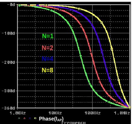
[image:5.595.316.540.72.256.2]through digital control word N. The observed wave shapes at different N are shown in “Figure 6” at 100KHz frequency. The CMPAM-2 was initially designed for a cut frequency of 16 kHz with N = 1, R = 3.3kΩ and C = 3nF. Then the pole frequency was controlled through digital control word N. The observed frequency responses of the filter for different control words are given in “Figure 7”.
Table 1: The aspect ratios of the MOSFETs of the DPCCII
MOSFETs W μm L μm M1, M2, M5, M6 5 0.25
M3, M4, M7, M8 0.5 0.5
M9, M10 0.5 0.25
M11, M12, M13, M14,
M15, M16,M17, M18,
M19, M23, M27, M31
25 0.25
M20, M24, M28, M32 50 0.25
M21, M25, M29, M33 100 0.25
M22, M26, M30, M34 200 0.25
IO+ I
O-N=1
N=2
N=4
N=8
N=15
Non-Inv CA:
N=1
N=2
N=4
N=8
N=15
Inv CA:
Fig 6: The output wave shapes at different control word N of the inverting and non-inverting current amplifier (CA)
at 100KHz.
ILP/Iin IHP/Iin N=4
N=2 N=1
N=8
N=4 N=2 N=1
N=8
Fig 7(a): Frequency response of LP and HP first order current mode filters at different control word N
IAP/Iin
N=4
N=1
N=2
N=8
Fig 7(b): Frequency response of the first order current mode AP filter at different control word N
N=4
N=1
N=2
N=8
Phase(IAP)
Fig 7(c): Variation of phase angle of the first order current mode AP filter at different control
[image:5.595.57.279.294.718.2] [image:5.595.319.539.297.480.2] [image:5.595.317.539.510.718.2]IIN IAP N=4
Fig 7(d): The input and output wave shapes of the first order all pass filter at ϕ = 900
The CMPAM-3 was initially designed for a pole frequency of f0 =46.8kHz and pole-Q = 1 with N =N0 = 1, R = 13.6kΩ and
C = 0.25nF. Then the pole frequency was controlled through digital control word N. The observed frequency responses of the filter for different control words are given in “Figure 8”. All the results observed in “Figure 6” through “Figure 8” show the close conformity with the design.
IBP/IIN IHP/IIN ILP/IIN
Fig 8(a): ): Frequency response of LP, HP and BP second order current mode filter at control word N = 2
N=4 N=2 N=1
N=8
ILP/Iin
Fig 8(b): Frequency response of LP second order current mode filter at different control word N
N=4 N=2
N=1
N=8
IHP/Iin
Fig 8(c): Frequency response of HP second order current mode filter at different control word N
IBP/IIN
N=1 N=2 N=4
N=8 N=15
Fig 8(d): Frequency response of the BP second order current mode filter at different control word N
N=4
N=2
N=1
N=8
IBR/Iin
[image:6.595.320.537.71.258.2] [image:6.595.60.277.73.211.2] [image:6.595.317.536.293.483.2] [image:6.595.58.279.322.500.2] [image:6.595.320.537.515.714.2] [image:6.595.59.276.532.719.2]N=4
N=2
N=1
N=8
I
AP/I
inFig 8(f): Frequency response of AP second order current mode filter at different control word N
N=1
N=2
N=4
N=8
Phase(IAP)
Fig 8(g): Variation of phase angle of the second order current mode AP filter at different control
word N
5.
CONCLUSION
Three current mode programmable analog modules are realized using digitally controlled low voltage CMOS current conveyors. These programmable modules include current mode amplifiers with inverting and non-inverting outputs, integrators, differentiators, first order multifunctional filter wit low pass, high pass, and all pass filter sections. The third programmable analog module realized is second order current mode multifunctional filter which provides low pass, high pass, band pass, band reject and all pass responses. All the realized current mode programmable analog module parameters are digitally programmable through an n-bit control word with high resolution capability and reconfigurability. These programmable analog modules are suitable for realizing current mode field programmable analog array. All the three realized programmable analog modules were designed with minimal passive components’ spread and verified using PSPICE. All the results thus obtained justify the theory.
6.
REFERENCES
[1] Hassan, T. M. and Mahmoud, S. A. 2007, Low voltage digitally programmable band pass filter with independent control, IEEE International Conference on Signal Processing and Communications (ICSPC 2007), 24-27, Dubai, UAE.
[2] Khan, I. A., Khan, M. R. and Afzal, N. 2006, Digitally programmable multifunctional filters using CCIIs, Journal of Active and Passive Electronic Devices, 1, 213-220.
[3] Khan, I. A., Khan, M. R. and Afzal, N. 2009, A Digitally Programmable Impedance Multiplier using CCIIs with High Resolution Capability, Journal of Active and Passive Electronic Devices, 8, 247-257.
[4] Hassan, T. M. and Mahmoud, S. A. 2009, Fully programmable universal filter with independent gain, ω0
and Q control based on new digitally programmable CMOS CCII, Journal of Circuits, Systems and Computers, 18, No. 5, 875-897.
[5] Mahmoud, S. A., Hashiesh, M. A. and Soliman, A. M. 2005, Low-voltage digitally controlled fully differential current conveyor," IEEE Transactions on circuits and Systems-I, 52, No. 10, 2055-2064.
[6] Khan, I. A. and Simsim, M. T. 2011, A Novel Impedance Multiplier using Low voltage Digitally Controlled CCII, Proc. IEEE GCC Conference and Exhibition, Dubai, UAE, 331-334.
[7] Khan, I. A., Simsim, M. T. and Beg, P. 2011, Reconfigurable Continuous Time Current Mode First Order Multifunctional Filter using Low voltage Digitally Controlled CMOS CCII, Proc. International Conference on Multimedia, Signal Processing and Communication Technologies (IMPACT-2011), 5-8, Aligarh, India. [8] Khan, I. A. and Nahhas, A. M. May, 2012,
Reconfigurable Voltage Mode First Order Multifunctional Filter using Single Low voltage Digitally Controlled CMOS CCII, International J. Computer Applications(To Appear).
[9] Pal, K. and Rana, S. 2004, Some new first order all-apss realization using CCII, J. Active and Passive Elec. Comp., 27, 91–94.
[10] Khan, I. A. and Maheshwari, S. 2000, Simple first order all-pass section using a single CCII, International Journal of Electronics, 87, No. 3, 303-306.
[11] Mita, R., Palumbo, G. and Pennisi, S. 2003, 1.5-V CMOS CCII+ with High Current-Drive Capability, IEEE Trans. CAS-II, 50, No. 4, 187-190.
[12] Madian, A. H., Mahmoud, S. A. and Soliman, A. M. 2006, New 1.5V CMOS second generation current conveyor based on wide range transconductor, Analog Integrated Circuits and Signal Processing, 49, 267-279. [13] Khan, I. A., Beg, P. and Ahmed, M. T. 2007, First Order
Current Mode Filters and Multiphase Sinusoidal Oscillators Using MOCCIIs, Arabian Journal of Science and Engineering, Saudi Arabia, 32, No. 2C, 119-126. [14] Beg, P., Khan, I. A. and Maheshwari, S. 2012, Biphase
Amplifier based Precision Rectifiers using Current Conveyors, International J. Computer Applications, 42, No. 3, 14-18.
[15] Floyd, T. L. 2012, Electronic Devices Conventional Current Version, Ninth Edition, Pearson.
[image:7.595.57.275.70.232.2] [image:7.595.57.278.275.482.2]