Designing an Embedded System for Autonomous
Building Map Exploration Robot
V. Ramya
Assist. Prof, Dept of CSE Annamalai University
Annamalai Nagar
T. Akilan
Dept. of CSE Annamalai University
Annamalai Nagar
N. Vignesh
Dept. of CSE Annamalai University
Annamalai Nagar
ABSTRACT
In many fields, the use of autonomous robots can provide significant benefits. Robots can be used to reduce the risk involved with human physical intrusion, especially in hazardous environments. They can approach the locations of attention to report sensory data and to show more detailed views of a mistrustful area. Moreover they can perform long-time tedious tasks that require reliable execution, without lowering their level of efficiency [3]. Robot navigation is defined as the combination of three basic activities such as, Map Building, Localization and Path planning. It is very important to have an accurate map and a reliable localization. All these information are sent to the display unit (Remote receiver) via RF module. The display unit is responsible for integrating all the sensory data collected by the robot and to provide the information as a map on the LCD display. Apart from viewing the map, the human operator could take important decisions about the path, with which the robot would take in special situations using the touch screen interface in the display unit. This type of robot would help civilians and military persons while dealing with dangerous situations like war and terrorist seeking operations. So this robot will help the first responders who could send this robot to quickly search the building structure and send back a map. This way they would have a much better sense of what to expect and they can work out a plan before entering into the building.
Keywords
MEMS, Ultrasonic sensor, LCD display, RF module, Robot.
1.
INTRODUCTION
Robotic mapping has been a highly active research area in robotics and AI for at least two decades. Robotic mapping addresses the problem of acquiring spatial models of physical environments through mobile robots [1]. This work attempts to provide a comprehensive overview of the state of the art in robotic mapping, with a focus on indoor static environments. To acquire a map, robots must possess sensors that enable it to perceive the outside world. The light and sound cannot penetrate walls. These range limitations makes it necessary for a robot to navigate through its environment when building a map. The motion commands (controls) issued during environment exploration carry important information for building maps, since they convey information about the locations at which different sensor measurements were taken [1].
1.1
Objective of the Work
The main objective of this work is to design an embedded system for Autonomous building map exploration robot for first responder and military operations.
To provides a comprehensive introduction into the field of robotic mapping, with a focus on indoor mapping.
To create a map with the help of ultrasonic sensor, and MEMS and to provide the mapping information to the remote person (Touch Screen) through RF module.
1.2
Slam Technique
SLAM (Simultaneous localization and mapping) technique is used by robots and autonomous vehicles to build up a map within an unknown environment, or to update a map within a known environment, while at the same time keeping track of their current location. Maps are used to depict an environment for planning and navigation; they support the assessment of actual location by recording information obtained from a form of perception and comparing it to a current set of perceptions. The benefit of a map in aiding the assessment of a location increases as the precision and quality of the current perceptions decrease [14]. Simultaneous localization and mapping (SLAM) is a concept that binds these processes in a loop and therefore supports the continuity of both aspects in separated processes; iterative feedback from one process to the other enhances the results of both consecutive steps. Mapping is the problem of integrating the information gathered by a set of sensors into a consistent model and depicting that information as a given representation.
1.3
Proposed System
A Digital MEMS Magnetometer is used to keep track of the direction and movement along it. The human operator could take important decisions about the path that the robot would take in special situations using the touch screen interface in the display unit. The brain of the robot and display unit is a 32-bit ARM Cortex-M3 microcontroller. This type of robot would help civilians and military persons while dealing with dangerous situations like war and terrorist seeking operations. So this robot will help the first responders who could send in this robot to quickly search the building structure and send back a map.
2.
SYSTEM DESIGN
2.1
Robotic Control
The Robot can be controlled wirelessly from outside the building. The display unit is designed around a 65K Color QVGA TFT Touch screen Graphics LCD, which displays the map of the static environment also the robot position by using MEMS [4].
[image:2.595.323.562.78.262.2] The robot interacts with the display unit using IEEE 802.15.4, a low power wireless network protocol (Figure 1).
Figure 1: Schematic diagram for Robot Control
2.2
Map Creation
[image:2.595.54.279.318.436.2]Mapping is done with the help of high precision Ultrasonic SONAR sensors. In this system, three ultrasonic sensors are used. One is placed in-front to the robot and other two sensors are placed left and right side of the robot. The left and right side ultrasonic sensor emits the ultrasonic sound waves and are propagates through air, if there is any obstacle within the range of the sensor frequency, the sound waves are return back, and are received by the receiver ultrasonic sensor [8]. The sensory information is sent to the microcontroller (Robot side) and processes the data and transfers the same to the display unit microcontroller. At display unit the map is drawn in the TFT touch screen display, according to the obstacle sensing information (Figure 2). The MEMS is placed at the robotic side, which is used to the display the current position of the robot.
Figure 2: Map creation of Static Environment
2.3
Obstacle Detection
The obstacle can be detected by using High precision ultrasonic sonar sensor. The front sonar sensor can cover the range up to 30 cm (Figure 3) and left and right side sonar sensor can detect the obstacle up to the range of 60 cm [10]. If any obstacle detected, the microcontroller gives the information about the obstacle detection to the authorized person, this robot will take right side direction and proceeds forward direction. If again any obstacle is detected it will ask the authorized person for selecting the direction of movement. The authorized person must select the direction (right or left) to the current position. The robotic wheel movement is done with the help of DC motors. There are four DC motors are fixed to each of the robot wheels. All the motors are connected to PWM (pulse width modulation) in the microcontroller residing at the robot and hence the direction of the robotic wheel movement is controlled.
[image:2.595.320.557.485.591.2]3.
HARDWARE DESCRIPTION
3.1
Microcontroller
[image:3.595.318.547.76.145.2]The LPC1313 is ARM Cortex-M3 based microcontrollers for embedded applications featuring a high level of integration and low power consumption. The LPC1313 operates at CPU frequencies of up to 72 MHz. The peripheral complement of the LPC1313 includes up to 32 kB of flash memory, up to 8 kB of data memory, USB Device (LPC1342/43 only), one Fast-mode Plus I2C-bus interface, one UART, four general purpose timers, and up to 42 general purpose I/O pins [6]. The front ultrasonic sensor is interfaced with the microcontroller’s pin 19 / port 2.4, and pin 20 / port 2.5, right ultrasonic sensor is interfaced with the microcontroller’s pin 46 / port1.6 and pin 47 / port 1.7, left ultrasonic sensor is interfaced with the pin 11 / port 2.7 and pin 2.6 / port 1. RF module is interfaced with the microcontroller’s pin 16, 15 and 29 to the corresponding ports SD0, SD1 and SCK. And the MEMS magnetometer is interfaced with the microcontroller’s port 15 and pin 0.4 and port 16 / pin 0.5. Pin diagram of LPC1313 Microcontroller is shown in figure 4.
Figure 4: ARM7 LPC1313 Microcontroller
3.2
L293D driver
[image:3.595.124.209.297.387.2]The L293D is designed to provide bidirectional drive currents of up to 600-mA at voltages from 4.5 V to 36 V. Drivers are enabled in pairs, with drivers 1 and 2 enabled by 1, 2 EN and drivers 3 and 4 enabled by 3, 4 EN. When an enable input is high the associated drivers are enabled, and their outputs are active and in phase with their inputs. When the enable input is low, those drivers are disabled, and their outputs are off and in the high-impedance state. With the proper data inputs, each pair of drivers forms a full-H (or bridge) reversible drive suitable for solenoid or motor applications [7].Figure 5 shows motor direction control. This driver is used to control the motor residing at the robot side. And it gets PWM frequency from the microcontroller and acts upon the received frequency.
Figure 5: Motor Direction Control
3.3
Ultrasonic Sensor
The SRF02 is a single transducer ultrasonic rangefinder in a small footprint PCB. It features both I2C and a serial interfaces (Figure 6). The serial interface is a standard TTL level UART format at 9600 baud, 1 start, 2 stop and no parity bits, and may be connected directly to the serial ports on any microcontroller. Up to 16 SRF02's may be connected together on a single bus, either I2C or Serial [9]. New commands in the
SRF02 include the ability to send an ultrasonic burst on its own without a reception cycle, and the ability to perform a reception cycle without the preceding burst. Because the SRF02 uses a single transducer for both transmission and reception, the minimum range is higher than our other dual transducer rangers [9]. The minimum measurement range is around 15cm (6 inches). Interfacing diagram for Ultrasonic sensor with Microcontroller is shown in Figure 7. In this work, the sensor is used to detect the in front obstacles and robot left and right side environments.
[image:3.595.339.520.399.512.2]Figure 7: Interfacing diagram for Ultrasonic sensor with Microcontroller
3.4
MEMS
[image:4.595.69.268.442.571.2]MicroElectroMechanical system, which measures magnetic fields, is distinct from metal detectors. When used for detecting metals, a magnetometer can detect only magnetic (ferrous) metals, but can detect such metals buried much deeper than a metal detector [11]. Magnetometers are capable of detecting large objects like cars at tens of meters, while a metal detector's range is unlikely to exceed 2 meters. Schematic Diagram of MEMS Magnetometer is shown in Figure 8. Interfacing diagram of MEMS with microcontroller is shown in Figure 9. The accurate position of the robot can be determined by using MEMS. It is interfaced with I2C bus in the microcontroller.
Figure 8: Schematic Diagram of MEMS Magnetometer
Figure 9: Interfacing diagram of MEMS with microcontroller
3.5
TFT Touch screen
[image:4.595.352.503.469.631.2]In RGB interface and VSYNC interface mode, the combined use of high-speed RAM write function and window address function enables to display a moving picture at a position specified by a user and still pictures in other areas on the screen simultaneously, which makes it possible to transfer display the refresh data only to minimize data transfers and power consumption (Figure 10). It can operate with 1.65V I/O interface voltage. [12].The ILI9325 also supports a function to display in 8 colors and a sleep mode, allowing for precise power control by software and these features make the ILI9325 an ideal LCD driver for medium or small size portable products such as digital cellular phones, smart phone, PDA and PMP where long battery life is a major concern. All the map information and also the control signals are recognized by the receiver device i.e. LCD touch screen display.
Figure 10: QVGA TFT LCD display
3.6
RF module
display unit is shown in Figure 11 and Figure 12. Communication between the robot and Touch Screen is through RF module. It is a low cost, and reliable device comparing with the other devices. It is placed at both sides (robot and display unit). It acts as transceiver while transmission.
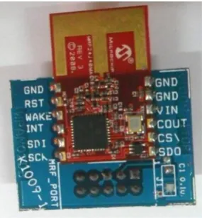
[image:5.595.326.528.276.603.2]Figure 11: Interfacing diagram for RF module with Microcontroller (Robot side)
Figure 12: Interfacing diagram for RF module with microcontroller (Display Unit)
3.7
DC Motor
A DC motor is a mechanically commutated electric motor powered from direct current (DC). The stator is stationary in space by definition and therefore its current. The current in the rotor is switched by the commutator to also be stationary in space. This is how the relative angle between the stator and rotor magnetic flux is maintained near 90 degrees, which generates the maximum torque (Figure 14). Different connections of the field and armature winding provide different inherent speed/torque regulation characteristics. The speed of a DC motor can be controlled by changing the voltage applied to the armature or by changing the field current [2]. Interfacing diagram for motor control with Microcontroller is shown in Figure 15. The robot is moved by using DC motors and this motor is connected to the L293D driver. This driver gets the PWM frequency and actuates the wheel movement. There are four motors are used to move the robot at desired direction.
[image:5.595.58.281.367.534.2]Figure 14: DC motors
Figure 15: Interfacing diagram for motor control with Microcontroller
4.
SOFTWARE DESCRIPTION
4.1
Embedded Software Development
[image:5.595.96.239.579.733.2] Programs must be as short as possible and memory must be used efficiently.
Programs must run as fast as possible. Ease of implementation.
Maintainability. Readability.
C compilers for embedded systems must provide ways to examine and utilize various features of the microcontroller's internal and external architecture; this includes:
Interrupt Service Routines.
Reading from and writing to internal and external memories.
Bit manipulation.
Implementation of timers / counters. Examination of internal registers.
4.2
Downloading tool (Flash Magic)
NXP Semiconductors produce a range of Microcontrollers that feature both on-chip Flash memory and the ability to be reprogrammed using In-System Programming technology [5]. Flash Magic is Windows software from the Embedded Systems Academy that allows easy access to all the ISP features provided by the devices. These features include:
Erasing the Flash memory (individual blocks or the whole device)
Programming the Flash memory
Modifying the Boot Vector and Status Byte Reading Flash memory
Performing a blank check on a section of Flash memory
Reading the signature bytes Reading and writing the security bits Direct load of a new baud rate (high speed
communications)
Sending commands to place device in Boot loader mode
Flash Magic only obtains access to the selected COM Port when ISP operations are being performed. This means that other applications that need to use the COM Port, such as debugging tools, may be used while Flash Magic is loaded.
4.3
Compiling, Debugging and linking tool
LPCXpresso is a new, low-cost development platform available from NXP. LPCXpresso is an end-to-end solution enabling embedded engineers to develop their applications from initial evaluation to final production [15]. It is an industry-standard GNU tool chain with an optimized C library that gives engineers all the tools necessary to develop high-quality software solutions quickly and cost-effectively. The C programming environment includes professional-level features. The LPCXpresso target board, jointly developed by NXP, Code Red Technologies, includes an integrated JTAG debugger (LPC-Link), so there’s no need for a separate JTAG debug probe. The target portion of the board can connect to expansion boards to provide a greater variety of interfaces, and I/O devices. The on-board LPC-Link debugger provides a high-speed USB to JTAG/SWD interface to the IDE and it can be connected to other debug targets such as a customer prototype [15].
5.
RESULTS AND DISCUSSION
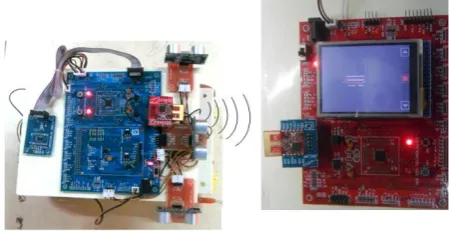
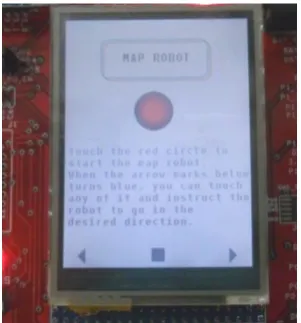
[image:6.595.334.524.180.293.2]The map is created by using MEMS and Ultrasonic sensor. The red line refers to the robot current position and the white line refers the robot right and left side obstacles. This display unit has ARM LPC 1313 Microcontroller (M2) which sends the robot control signals to the robot. Figure 16 shows the prototype of the display unit. And Figure 17 shows the prototype of the robot.
Figure 16: Prototype of the Display Unit
Figure 17: Prototype of the Robot
[image:6.595.321.532.321.485.2]6.
CONCLUSION
The goal of the map exploration mobile robot is to move the robot to a specified destination in unknown static environment; in most practical situation the mobile robot can’t take a direct path from the start to the goal point, therefore path finding techniques must be used.In this work, the map creation is possible by using high precision ultrasonic sensor and MEMS. By using RF module all the sensory information can be sent easily to the authorized user, who is outside the building. The developed system has a benefit to access the robot from outside the building. The future enhancement in this project is that we can add camera to the existing robot for getting access in non-visible area and the robot can also work as a spy robot that can be used for those area where human cannot enter directly.
7.
REFERENCES
[1] O. Hachour 2009. “The proposed path finding strategy in static unknown environments”, International Journal of Systems Applications, Engineering & Development, Issue 4, vol. 3. [2] Datasheet 2013, DC motors, Precision Microdrives
Limited.
[3] Sebastian Thrun. February 2002. “Robotic Mapping: A Survey”.
[4] R. Gupta, UC Irvine. 2002. “Introduction to Embedded Systems”.
[5] Datasheet, “Flash Magic GUI and Command Line Manual”.
[6] NXP – Arrow Seminars. June 2012. “ARM Cortex-M Continuum:From Cortex-M0 to Dual-core Cortex-M4”. [7] Motor driver IC-L293D, Datasheet-Atmel
Corporation; http://www.atmel.com/products/avr. [8] Jaroslav Moravec. 2012. “Map Building of
Unknown Environment Using L1-norm, Point-to-Point Metric and Evolutionary Computation”, pp.29-38.
[9] Datasheet, “SRF02 Ultrasonic range finder Technical Specification”.
[10]Tarek Mohammad. 2009. “Using Ultrasonic and Infrared Sensors for Distance Measurement”, World Academy of Science, Engineering and Technology. [11]Datasheet 2008, Freescale Semiconductor,
Technical Data.
[12]Datasheet, “a-Si TFT LCD Single Chip Driver 240RGBx320 Resolution and 262K color”.
[13]Datasheet 2008, “MRF24J40MA”, Microchip Technology Inc.
[14]J.O. Wallgrün. 2010. “Hierarchical Voronoi Graphs: Spatial Representation and Reasoning for Mobile Robots”, Springer-Verlag Berlin Heidelberg. [15]Datasheet April 2011. “LPCXpresso Getting started